________________________________________________________________________
SpectreRF Workshop
LNA Design Using SpectreRF
MMSIM 13.1
September 2013
September 2013 Product Version 13.1
�
________________________________________________________________________
LNA Design Using SpectreRF
Contents
LNA Design Using SpectreRF............................................................................................ 3
Purpose ............................................................................................................................ 3
Audience ......................................................................................................................... 3
Overview ......................................................................................................................... 3
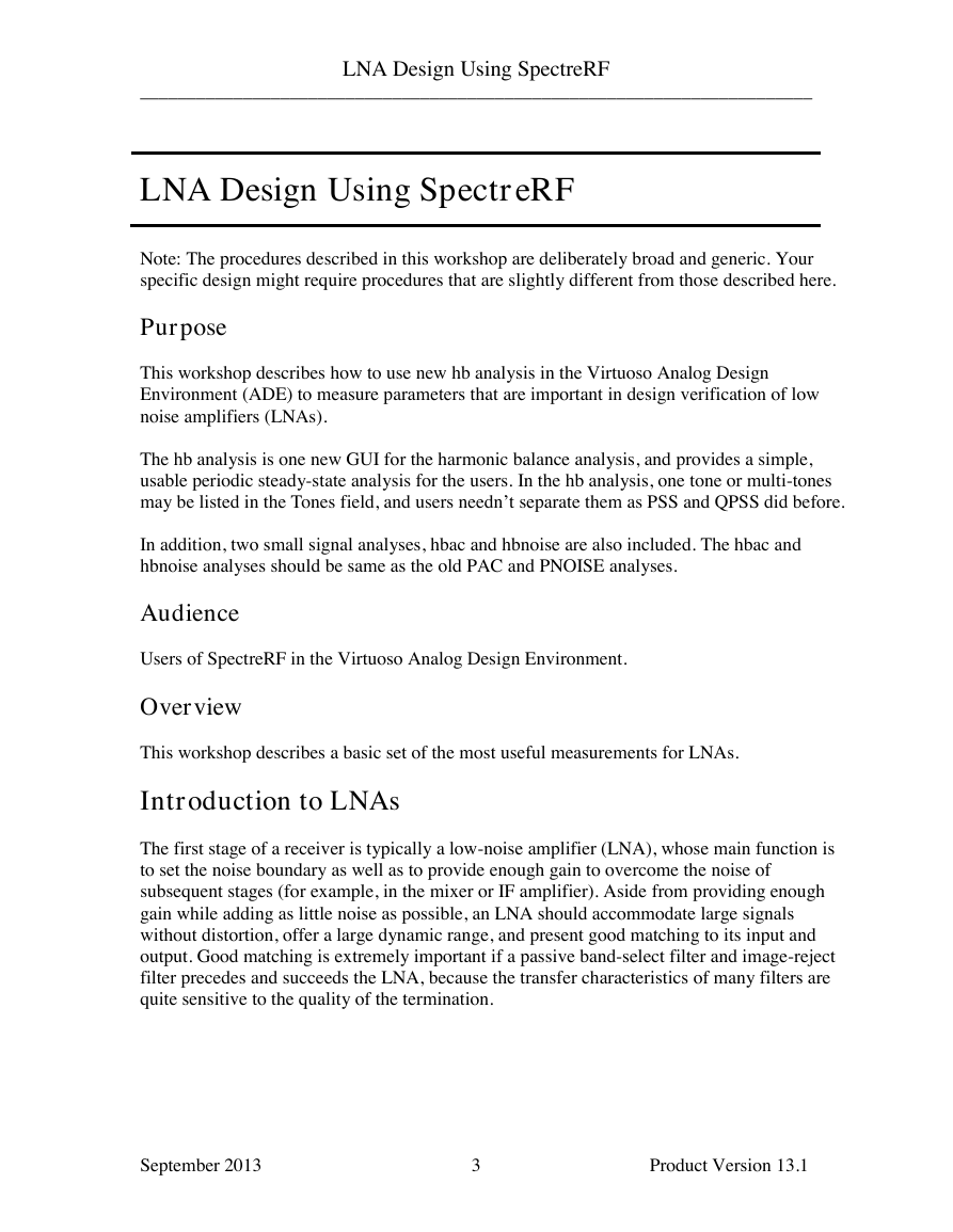
Introduction to LNAs .......................................................................................................... 3
The Design Example: A Differential LNA ......................................................................... 4
Testbench ........................................................................................................................ 5
LNA Measurements and Design Specifications ................................................................. 7
Example Measurements Using SpectreRF........................................................................ 14
Lab 1: Small Signal Gain (SP) ...................................................................................... 15
Lab 2: Noise Simulation ( hb and hbnoise ) ................................................................. 29
Lab 3: Gain Compression and THD (Xdb and Swept hb) ............................................ 36
Lab 4: IP3 Measurement---hb/hbac analysis ................................................................ 47
Lab 5: IP3 Measurement---hb Analysis with Two Tones ............................................. 54
Lab 6: IP3 Measurement---Rapid IP3 using AC analysis ............................................. 58
Conclusion ........................................................................................................................ 62
References ......................................................................................................................... 62
September 2013 Product Version 13.1
2
�
________________________________________________________________________
LNA Design Using SpectreRF
LNA Design Using SpectreRF
Note: The procedures described in this workshop are deliberately broad and generic. Your
specific design might require procedures that are slightly different from those described here.
Purpose
This workshop describes how to use new hb analysis in the Virtuoso Analog Design
Environment (ADE) to measure parameters that are important in design verification of low
noise amplifiers (LNAs).
The hb analysis is one new GUI for the harmonic balance analysis, and provides a simple,
usable periodic steady-state analysis for the users. In the hb analysis, one tone or multi-tones
may be listed in the Tones field, and users needn’t separate them as PSS and QPSS did before.
In addition, two small signal analyses, hbac and hbnoise are also included. The hbac and
hbnoise analyses should be same as the old PAC and PNOISE analyses.
Audience
Users of SpectreRF in the Virtuoso Analog Design Environment.
Overview
This workshop describes a basic set of the most useful measurements for LNAs.
Introduction to LNAs
The first stage of a receiver is typically a low-noise amplifier (LNA), whose main function is
to set the noise boundary as well as to provide enough gain to overcome the noise of
subsequent stages (for example, in the mixer or IF amplifier). Aside from providing enough
gain while adding as little noise as possible, an LNA should accommodate large signals
without distortion, offer a large dynamic range, and present good matching to its input and
output. Good matching is extremely important if a passive band-select filter and image-reject
filter precedes and succeeds the LNA, because the transfer characteristics of many filters are
quite sensitive to the quality of the termination.
September 2013 Product Version 13.1
3
�
________________________________________________________________________
LNA Design Using SpectreRF
The Design Example: A Differential LNA
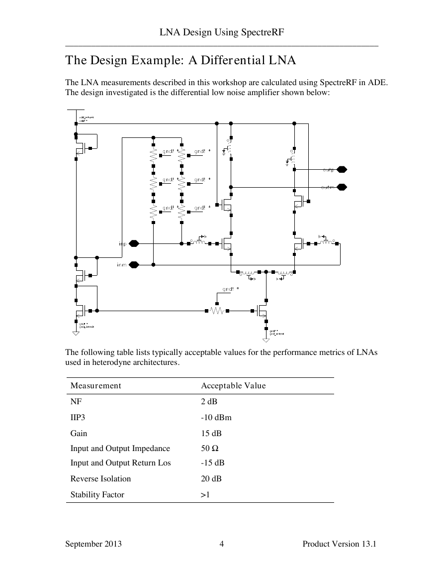
The LNA measurements described in this workshop are calculated using SpectreRF in ADE.
The design investigated is the differential low noise amplifier shown below:
The following table lists typically acceptable values for the performance metrics of LNAs
used in heterodyne architectures.
Measurement
Acceptable Value
NF
IIP3
Gain
Input and Output Impedance
2 dB
-10 dBm
15 dB
50 Ω
Input and Output Return Los
-15 dB
Reverse Isolation
Stability Factor
20 dB
>1
September 2013 Product Version 13.1
4
�
________________________________________________________________________
LNA Design Using SpectreRF
Testbench
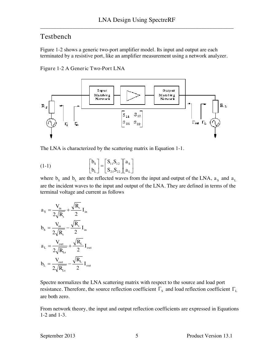
Figure 1-2 shows a generic two-port amplifier model. Its input and output are each
terminated by a resistive port, like an amplifier measurement using a network analyzer.
Figure 1-2 A Generic Two-Port LNA
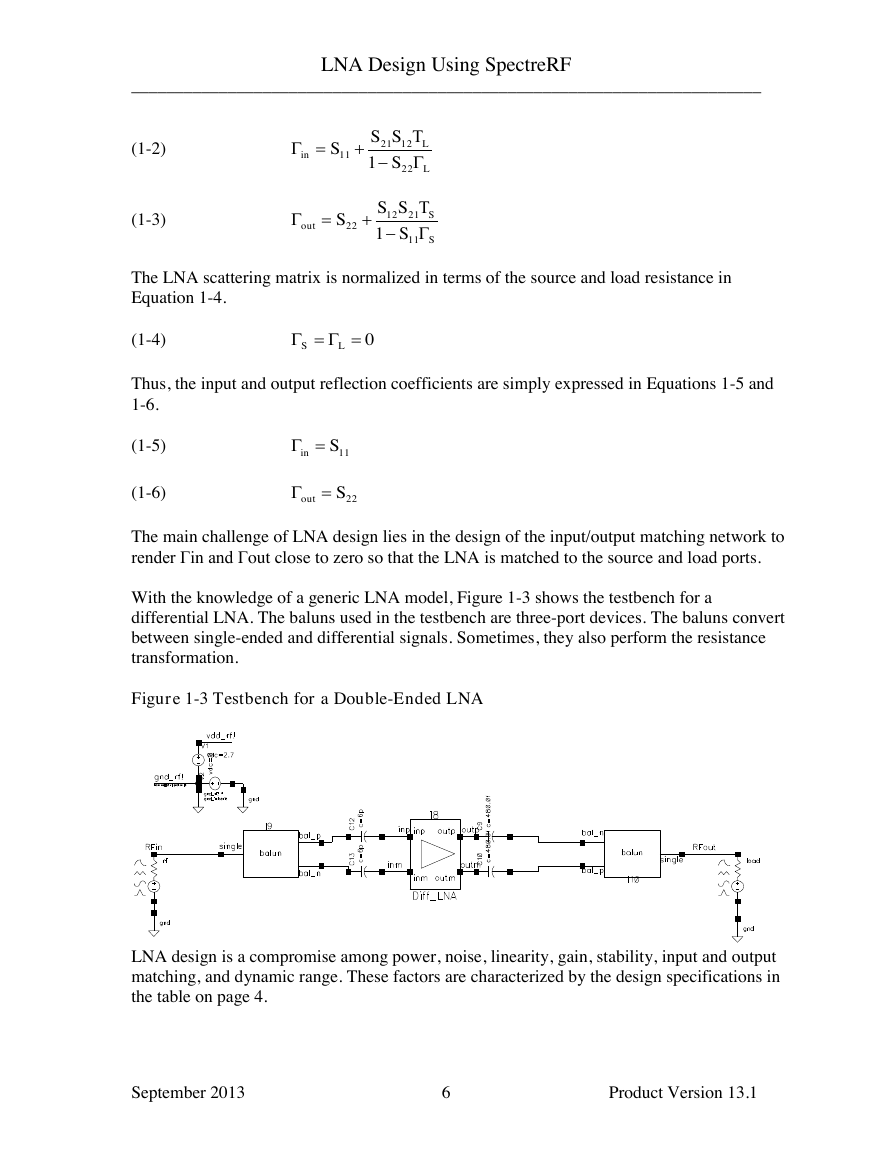
The LNA is characterized by the scattering matrix in Equation 1-1.
(1-1)
where
and
are the reflected waves from the input and output of the LNA,
and
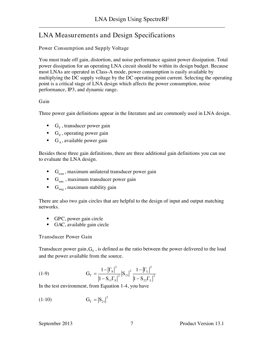
are the incident waves to the input and output of the LNA. They are defined in terms of the
terminal voltage and current as follows
Spectre normalizes the LNA scattering matrix with respect to the source and load port
resistance. Therefore, the source reflection coefficient
and load reflection coefficient
are both zero.
From network theory, the input and output reflection coefficients are expressed in Equations
1-2 and 1-3.
September 2013 Product Version 13.1
5
LSLSaaSSSSbb22211211SbLbSaLainssinSIRRVa22inssinSIRRVb22outLLsoutLIRRVa22outLLsoutLIRRVb22SL�
________________________________________________________________________
LNA Design Using SpectreRF
(1-2)
(1-3)
The LNA scattering matrix is normalized in terms of the source and load resistance in
Equation 1-4.
(1-4)
Thus, the input and output reflection coefficients are simply expressed in Equations 1-5 and
1-6.
(1-5)
(1-6)
The main challenge of LNA design lies in the design of the input/output matching network to
render Γin and Γout close to zero so that the LNA is matched to the source and load ports.
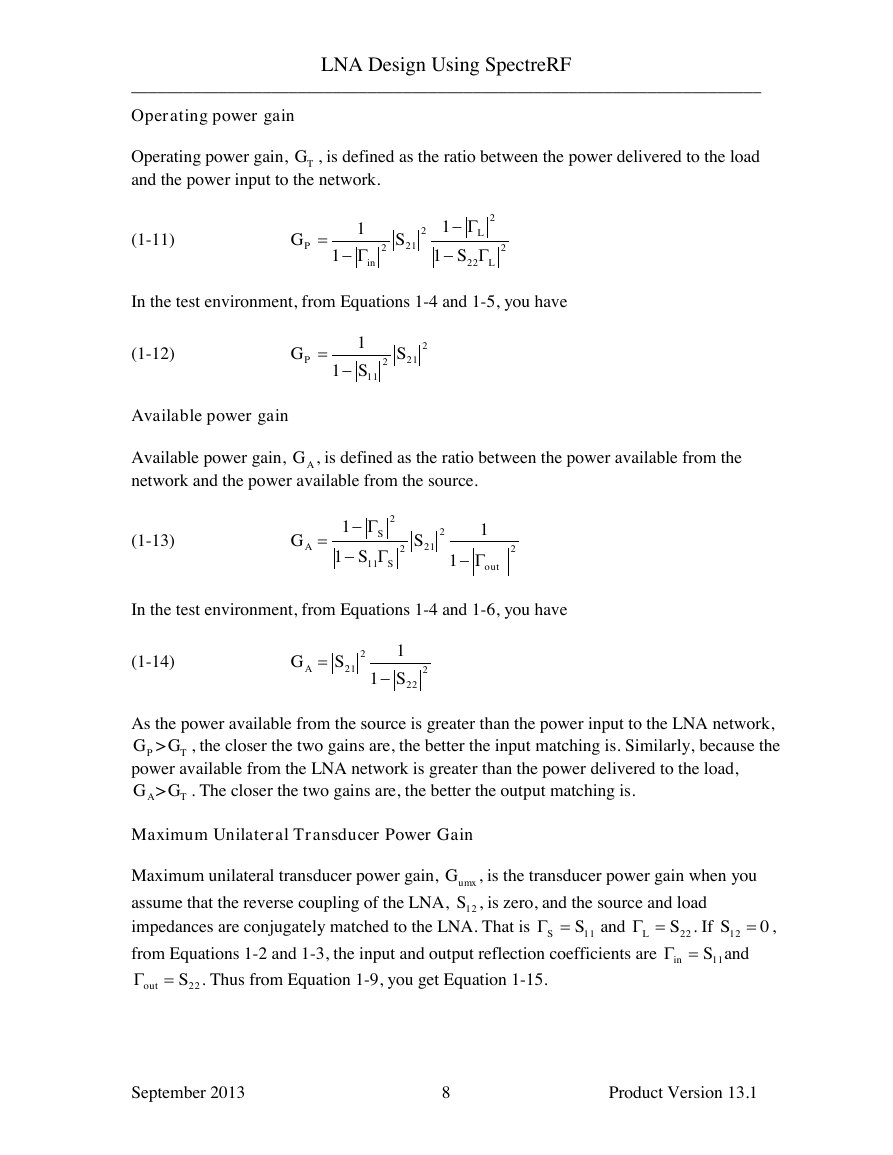
With the knowledge of a generic LNA model, Figure 1-3 shows the testbench for a
differential LNA. The baluns used in the testbench are three-port devices. The baluns convert
between single-ended and differential signals. Sometimes, they also perform the resistance
transformation.
Figure 1-3 Testbench for a Double-Ended LNA
LNA design is a compromise among power, noise, linearity, gain, stability, input and output
matching, and dynamic range. These factors are characterized by the design specifications in
the table on page 4.
September 2013 Product Version 13.1
6
LLinSSSS221221111SSoutSSSS1121122210LS11Sin22Sout�
________________________________________________________________________
LNA Design Using SpectreRF
LNA Measurements and Design Specifications
Power Consumption and Supply Voltage
You must trade off gain, distortion, and noise performance against power dissipation. Total
power dissipation for an operating LNA circuit should be within its design budget. Because
most LNAs are operated in Class-A mode, power consumption is easily available by
multiplying the DC supply voltage by the DC operating point current. Selecting the operating
point is a critical stage of LNA design which affects the power consumption, noise
performance, IP3, and dynamic range.
Gain
Three power gain definitions appear in the literature and are commonly used in LNA design.
, transducer power gain
, operating power gain
, available power gain
Besides these three gain definitions, there are three additional gain definitions you can use
to evaluate the LNA design.
, maximum unilateral transducer power gain
, maximum transducer power gain
, maximum stability gain
There are also two gain circles that are helpful to the design of input and output matching
networks.
GPC, power gain circle
GAC, available gain circle
Transducer Power Gain
Transducer power gain,
and the power available from the source.
, is defined as the ratio between the power delivered to the load
(1-9)
In the test environment, from Equation 1-4, you have
(1-10)
September 2013 Product Version 13.1
7
TGPGAGumxGmaxGmsgGTG222222121121111LLSSTSSSG221SGT�
________________________________________________________________________
LNA Design Using SpectreRF
Operating power gain
Operating power gain,
and the power input to the network.
, is defined as the ratio between the power delivered to the load
(1-11)
In the test environment, from Equations 1-4 and 1-5, you have
(1-12)
Available power gain
Available power gain,
network and the power available from the source.
, is defined as the ratio between the power available from the
(1-13)
In the test environment, from Equations 1-4 and 1-6, you have
(1-14)
As the power available from the source is greater than the power input to the LNA network,
, the closer the two gains are, the better the input matching is. Similarly, because the
>
power available from the LNA network is greater than the power delivered to the load,
>
. The closer the two gains are, the better the output matching is.
Maximum Unilateral Transducer Power Gain
Maximum unilateral transducer power gain,
, is the transducer power gain when you
assume that the reverse coupling of the LNA,
, is zero, and the source and load
impedances are conjugately matched to the LNA. That is
and
. If
,
from Equations 1-2 and 1-3, the input and output reflection coefficients are
and
. Thus from Equation 1-9, you get Equation 1-15.
September 2013 Product Version 13.1
8
TG222222121111LLinPSSG22121111SSGPAG222121121111outSSASSG22222111SSGAPGTGAGTGumxG12S11SS22SL012S11Sin22Sout�


 2023年江西萍乡中考道德与法治真题及答案.doc
 2012年重庆南川中考生物真题及答案.doc
 2013年江西师范大学地理学综合及文艺理论基础考研真题.doc
 2020年四川甘孜小升初语文真题及答案I卷.doc
 2020年注册岩土工程师专业基础考试真题及答案.doc
 2023-2024学年福建省厦门市九年级上学期数学月考试题及答案.doc
 2021-2022学年辽宁省沈阳市大东区九年级上学期语文期末试题及答案.doc
 2022-2023学年北京东城区初三第一学期物理期末试卷及答案.doc
 2018上半年江西教师资格初中地理学科知识与教学能力真题及答案.doc
 2012年河北国家公务员申论考试真题及答案-省级.doc
 2020-2021学年江苏省扬州市江都区邵樊片九年级上学期数学第一次质量检测试题及答案.doc
 2022下半年黑龙江教师资格证中学综合素质真题及答案.doc