关 键 词:配置
阅读提示:本文涵盖了 OSPF 配置的诸多示例
OSPF 配置示例(1)
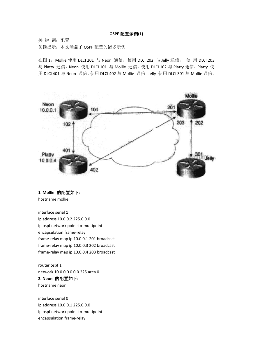
在图 1,Mollie 使用 DLCI 201 与 Neon 通信,使用 DLCI 202 与 Jelly 通信, 使 用 DLCI 203
与 Platty 通信。Neon 使用 DLCI 101 与 Mollie 通信,使用 DLCI 102 与 Platty 通信。Platty 使
用 DLCI 401 与 Neon 通信,使用 DLCI 402 与 Mollie 通信。Jelly 使用 DLCI 301 与 Mollie 通信。
1. Mollie 的配置如下:
hostname mollie
!
interface serial 1
ip address 10.0.0.2 225.0.0.0
ip ospf network point-to-multipoint
encapsulation frame-relay
frame-relay map ip 10.0.0.1 201 broadcast
frame-relay map ip 10.0.0.3 202 broadcast
frame-relay map ip 10.0.0.4 203 broadcast
!
router ospf 1
network 10.0.0.0 0.0.0.225 area 0
2. Neon 的配置如下:
hostname neon
!
interface serial 0
ip address 10.0.0.1 225.0.0.0
ip ospf network point-to-multipoint
encapsulation frame-relay
�
frame-relay map ip 10.0.0.2 101 broadcast
frame-relay map ip 10.0.0.4 102 broadcast
!
router ospf 1
network 10.0.0.0 0.0.0.255 area 0
3. Platty 的配置如下:
hostname platty
!
interface seria1 3
ip address 10.0.0.4 255.0.0.0
ip ospf network point-to-multipoint
encapsulation frame-relay
clock rate 1000000
frame-relay map ip 10.0.0.1 401 broadcast
frame-relay map ip 10.0.0.2 402 broadcast
!
router ospf 1
network 10.0.0.0 0.0.0.255 area 0
4. Jelly 的配置如下:
hostname jelly
!
interface seria1 2
ip address 10.0.0.3 255.0.0.0
ip ospf network point-multipoint
encapsulation frame-relay
clock rate 2000000
frame-relay map ip 10.0.0.2 301 broadcast
!
router ospf 1
network 10.0.0.0 0.0.0.255 area 0
OSPF 一对多接口广播示例
OSPF 配置示例(2)
下例为广播形式的一对多接口网络配置:
interface Serial 0
ip address 10.0.1.1 255.255.255.0
encapsulation frame-relay
ip ospf cost 100
ip ospf network point-to-multipoint
frame-relay map ip 10.0.1.3 202 broadcast
�
frame-relay map ip 10.0.1.4.203 broadcast
frame-relay map ip 10.0.1.5 204 broadcast
frame-relay local-dlci 200
!
router ospf 1
network 10.0.1.0 0.0.0.255 area 0
neighbor 10.0.1.5 cost 5
neighbor 10.0.1.4 cost 10
下例显示的是 10.0.1.3 上的邻居配置:
interface serial 0
ip address 10.0.1.3 255.255.255.0
ip ospf network point-to-multipoint
encapsulation frame-relay
frame-relay local-dlci 301
frame-relay map ip 10.0.1.1 300 broadcast
no shut
!
router ospf 1
network 10.0.1.0 0.0.0.255 area 0
上面第一个配置中的邻居的输出显示类似如下:
Router# show ip ospf neighbor
Neighbor ID
Pri State
Dead Time
Address
Interface
4.1.1.1
3.1.1.1
2.1.1.1
1 FULL/ -
00:01:50
10.0.1.5
Serial0
1 FULL/ -
00:01:47
10.0.1.4
Serial0
1 FULL/ -
00:01:45
10.0.1.3
Serial0
上面第一个配置中的路由信息类似如下:
Router# show ip route
Codes: Connected, S-static, I-IGRP, R-RIP, M-mobile, B-BGP D-EIGRP, EX-EIGRP
external, O-OSPF, IA-OSPF inter area
N1-OSPF NSSA external type 1, N2-OSPF NSSA external type 2
E1-OSPF external type 1, E2-OSPF external type 2, E-EGP i-IS-IS, L1-IS-IS level-1,
L2-IS-IS level-2, *-candidate defaultU-per-user static route, o-ODR
�
Gateway of last resort is not set
C 1.0.0.0/8 is directly connected, Loopback0
10.0.0.0/8 is variably subnetted,4 subnets, 2 masks
10.0.1.3/32 [110/100] via 10.0.1.3, 00:39:08, Serial0
C 10.0.1.0/24 is directly connected, Serial0
10.0.1.5/32 [110/5] via 10.0.1.5, 00:39:08, Serial0
10.0.1.4/32 [110/10] via 10.0.1.4, 00:39:08, Serial0
OSPF 一对多非广播示例下例为非广播形式的一对多网络配置: interface Serial0
OSPF 一对多非广播示例下例
为非广播形式的一对多网络配置:
interface Serial0
ip address 10.0.1.1 255.255.255.0
ip ospf network point-to-multipointnon-broadcast
encapsulation frame-relay
no keepalive
frame-relay local-dlci 200
frame-relay map ip 10.0.1.3 202
frame-relay map ip 10.0.1.4 203
frame-relay map ip 10.0.1.5 204
no shut
!
router ospf 1
network 10.0.1.0 0.0.0.255 area 0
neighbor 10.0.1.3 cost 5
neighbor 10.0.1.4 cost 10
neighbor 10.0.1.5.cost 15
下例是另一端路由器上的配置:
interface Serial9/2
ip address 10.0.1.3 255.255.255.0
�
encapsulation frame-relay
ip ospf network point-to-multipoint non-broadcast
no ip mroute-cache
no keepalive
no fair-queue
frame-relay local-dlci 301
frame-relay map ip 10.0.1.1 300
no shut
!
router ospf 1
network 10.0.1.0
0.0.0.255 area 0
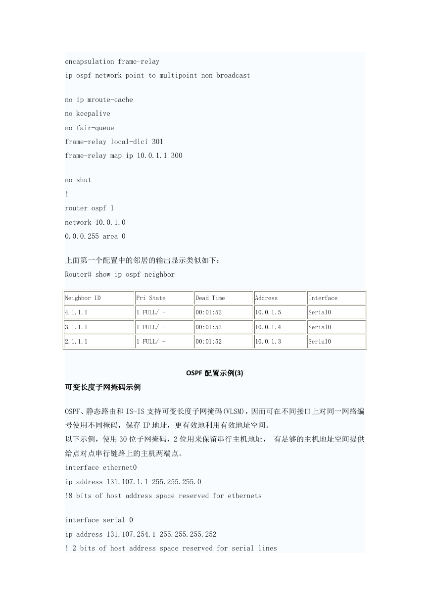
上面第一个配置中的邻居的输出显示类似如下:
Router# show ip ospf neighbor
Neighbor ID
Pri State
Dead Time
Address
Interface
4.1.1.1
3.1.1.1
2.1.1.1
1 FULL/ -
00:01:52
10.0.1.5
Serial0
1 FULL/ -
00:01:52
10.0.1.4
Serial0
1 FULL/ -
00:01:52
10.0.1.3
Serial0
可变长度子网掩码示例
OSPF 配置示例(3)
OSPF、静态路由和 IS-IS 支持可变长度子网掩码(VLSM),因而可在不同接口上对同一网络编
号使用不同掩码,保存 IP 地址,更有效地利用有效地址空间。
以下示例,使用 30 位子网掩码,2 位用来保留串行主机地址, 有足够的主机地址空间提供
给点对点串行链路上的主机两端点。
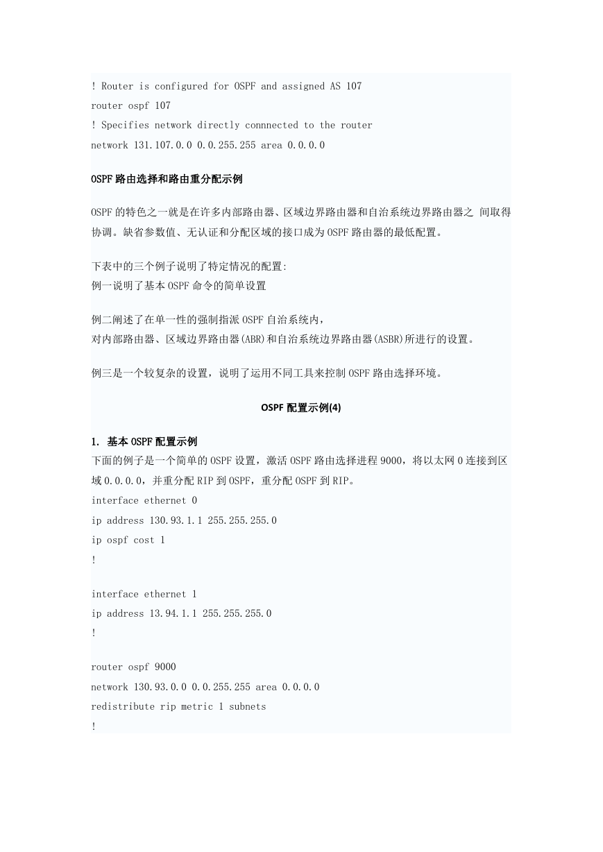
interface ethernet0
ip address 131.107.1.1 255.255.255.0
!8 bits of host address space reserved for ethernets
interface serial 0
ip address 131.107.254.1 255.255.255.252
! 2 bits of host address space reserved for serial lines
�
! Router is configured for OSPF and assigned AS 107
router ospf 107
! Specifies network directly connnected to the router
network 131.107.0.0 0.0.255.255 area 0.0.0.0
OSPF 路由选择和路由重分配示例
OSPF 的特色之一就是在许多内部路由器、区域边界路由器和自治系统边界路由器之 间取得
协调。缺省参数值、无认证和分配区域的接口成为 OSPF 路由器的最低配置。
下表中的三个例子说明了特定情况的配置:
例一说明了基本 OSPF 命令的简单设置
例二阐述了在单一性的强制指派 OSPF 自治系统内,
对内部路由器、区域边界路由器(ABR)和自治系统边界路由器(ASBR)所进行的设置。
例三是一个较复杂的设置,说明了运用不同工具来控制 OSPF 路由选择环境。
OSPF 配置示例(4)
1. 基本 OSPF 配置示例
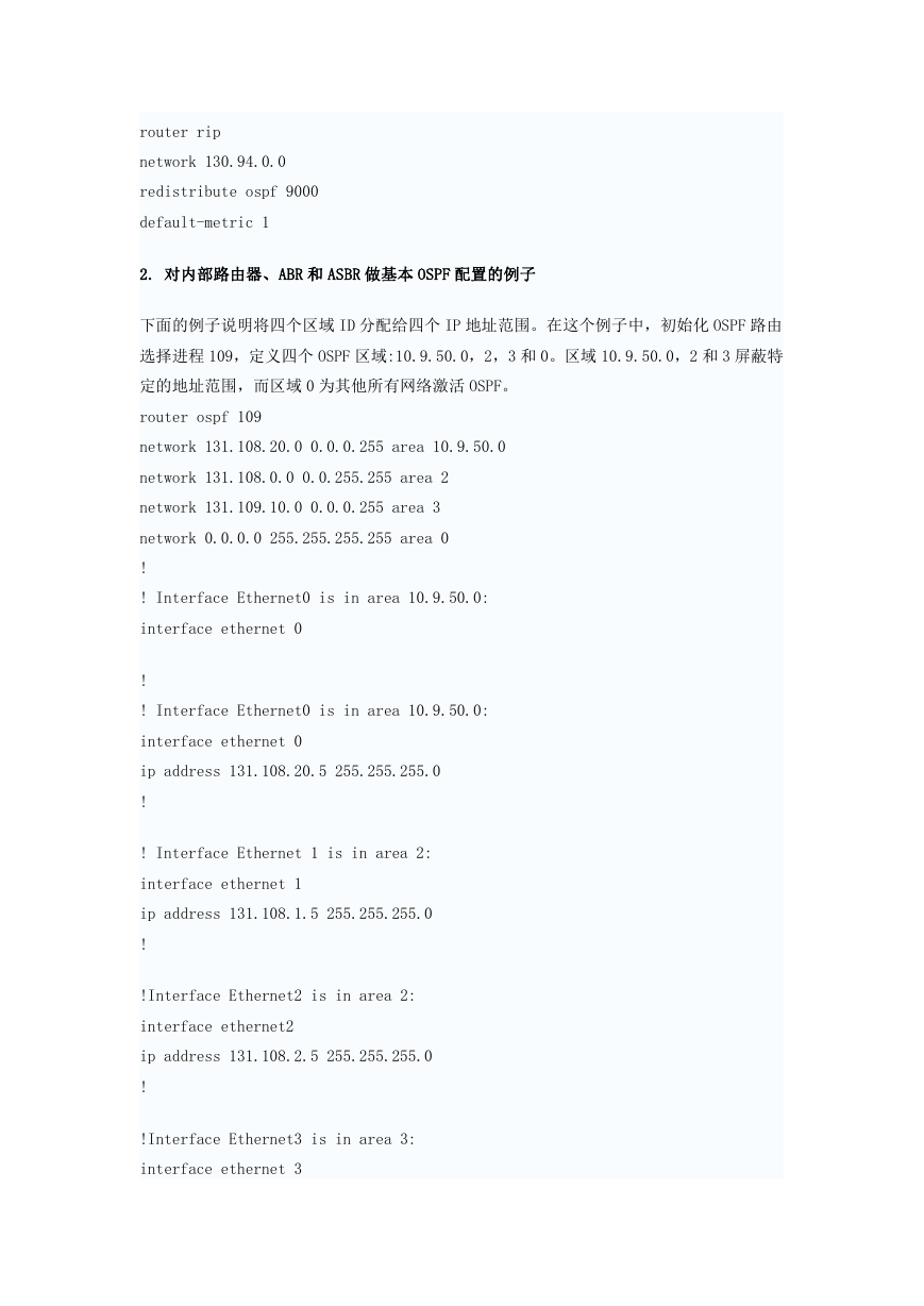
下面的例子是一个简单的 OSPF 设置,激活 OSPF 路由选择进程 9000,将以太网 0 连接到区
域 0.0.0.0,并重分配 RIP 到 OSPF,重分配 OSPF 到 RIP。
interface ethernet 0
ip address 130.93.1.1 255.255.255.0
ip ospf cost 1
!
interface ethernet 1
ip address 13.94.1.1 255.255.255.0
!
router ospf 9000
network 130.93.0.0 0.0.255.255 area 0.0.0.0
redistribute rip metric 1 subnets
!
�
router rip
network 130.94.0.0
redistribute ospf 9000
default-metric 1
2. 对内部路由器、ABR 和 ASBR 做基本 OSPF 配置的例子
下面的例子说明将四个区域 ID 分配给四个 IP 地址范围。在这个例子中,初始化 OSPF 路由
选择进程 109,定义四个 OSPF 区域:10.9.50.0,2,3 和 0。区域 10.9.50.0,2 和 3 屏蔽特
定的地址范围,而区域 0 为其他所有网络激活 OSPF。
router ospf 109
network 131.108.20.0 0.0.0.255 area 10.9.50.0
network 131.108.0.0 0.0.255.255 area 2
network 131.109.10.0 0.0.0.255 area 3
network 0.0.0.0 255.255.255.255 area 0
!
! Interface Ethernet0 is in area 10.9.50.0:
interface ethernet 0
!
! Interface Ethernet0 is in area 10.9.50.0:
interface ethernet 0
ip address 131.108.20.5 255.255.255.0
!
! Interface Ethernet 1 is in area 2:
interface ethernet 1
ip address 131.108.1.5 255.255.255.0
!
!Interface Ethernet2 is in area 2:
interface ethernet2
ip address 131.108.2.5 255.255.255.0
!
!Interface Ethernet3 is in area 3:
interface ethernet 3
�
ip address 131.109.10.5 255.255.255.0
!
!Interface Ethernet4 is in area 0:
interface ethernet 4
ip address 131.109.1.1 255.255.255.0
!
!Interface Ethernet5 is in area 0:
interface ethernet 5
ip address 10.1.0.1 255.255.0.0
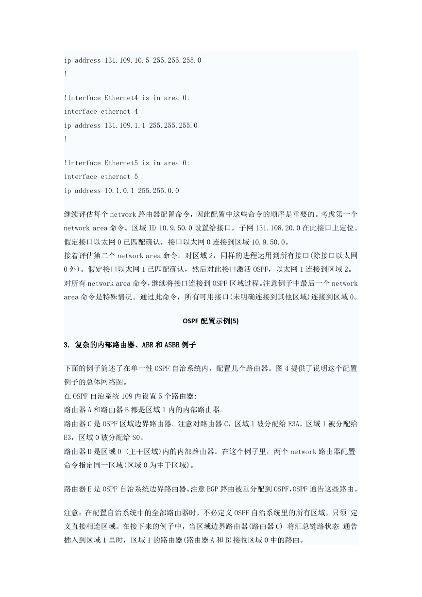
继续评估每个 network 路由器配置命令,因此配置中这些命令的顺序是重要的。考虑第一个
network area 命令。区域 ID 10.9.50.0 设置给接口,子网 131.108.20.0 在此接口上定位。
假定接口以太网 0 已匹配确认,接口以太网 0 连接到区域 10.9.50.0。
接着评估第二个 network area 命令。对区域 2,同样的进程运用到所有接口(除接口以太网
0 外)。假定接口以太网 1 已匹配确认,然后对此接口激活 OSPF,以太网 1 连接到区域 2。
对所有 network area 命令,继续将接口连接到 OSPF 区域过程。注意例子中最后一个 network
area 命令是特殊情况。通过此命令,所有可用接口(未明确连接到其他区域)连接到区域 0。
OSPF 配置示例(5)
3. 复杂的内部路由器、ABR 和 ASBR 例子
下面的例子简述了在单一性 OSPF 自治系统内,配置几个路由器。图 4 提供了说明这个配置
例子的总体网络图。
在 OSPF 自治系统 109 内设置 5 个路由器:
路由器 A 和路由器 B 都是区域 1 内的内部路由器。
路由器 C 是 OSPF 区域边界路由器。注意对路由器 C,区域 1 被分配给 E3A,区域 1 被分配给
E3,区域 0 被分配给 S0。
路由器 D 是区域 0 (主干区域)内的内部路由器。在这个例子里,两个 network 路由器配置
命令指定同一区域(区域 0 为主干区域)。
路由器 E 是 OSPF 自治系统边界路由器。注意 BGP 路由被重分配到 OSPF,OSPF 通告这些路由。
注意:在配置自治系统中的全部路由器时,不必定义 OSPF 自治系统里的所有区域,只须 定
义直接相连区域。在接下来的例子中,当区域边界路由器(路由器 C) 将汇总链路状态 通告
插入到区域 1 里时,区域 1 的路由器(路由器 A 和 B)接收区域 0 中的路由。
�


 2023年江西萍乡中考道德与法治真题及答案.doc
 2012年重庆南川中考生物真题及答案.doc
 2013年江西师范大学地理学综合及文艺理论基础考研真题.doc
 2020年四川甘孜小升初语文真题及答案I卷.doc
 2020年注册岩土工程师专业基础考试真题及答案.doc
 2023-2024学年福建省厦门市九年级上学期数学月考试题及答案.doc
 2021-2022学年辽宁省沈阳市大东区九年级上学期语文期末试题及答案.doc
 2022-2023学年北京东城区初三第一学期物理期末试卷及答案.doc
 2018上半年江西教师资格初中地理学科知识与教学能力真题及答案.doc
 2012年河北国家公务员申论考试真题及答案-省级.doc
 2020-2021学年江苏省扬州市江都区邵樊片九年级上学期数学第一次质量检测试题及答案.doc
 2022下半年黑龙江教师资格证中学综合素质真题及答案.doc