ANSYS Fluent Tutorial Guide
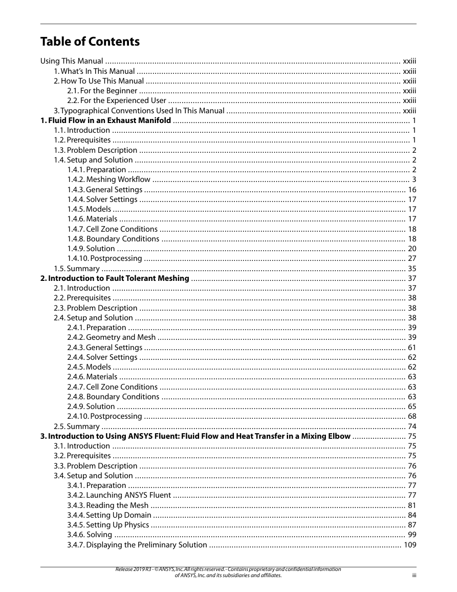
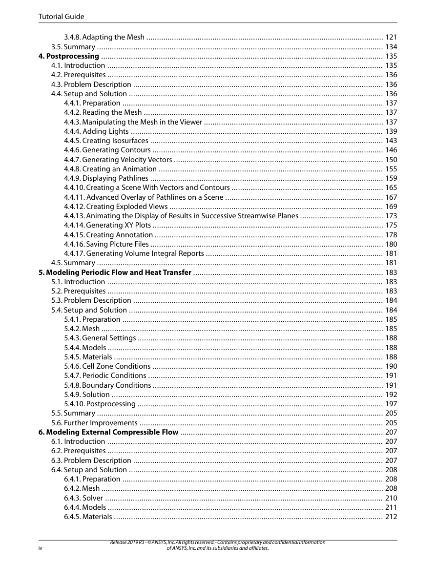
Table of Contents
Using This Manual
1. What’s In This Manual
2. How To Use This Manual
2.1. For the Beginner
2.2. For the Experienced User
3. Typographical Conventions Used In This Manual
Chapter 1: Fluid Flow in an Exhaust Manifold
1.1. Introduction
1.2. Prerequisites
1.3. Problem Description
1.4. Setup and Solution
1.4.1. Preparation
1.4.2. Meshing Workflow
1.4.3. General Settings
1.4.4. Solver Settings
1.4.5. Models
1.4.6. Materials
1.4.7. Cell Zone Conditions
1.4.8. Boundary Conditions
1.4.9. Solution
1.4.10. Postprocessing
1.5. Summary
Chapter 2: Introduction to Fault Tolerant Meshing
2.1. Introduction
2.2. Prerequisites
2.3. Problem Description
2.4. Setup and Solution
2.4.1. Preparation
2.4.2. Geometry and Mesh
2.4.3. General Settings
2.4.4. Solver Settings
2.4.5. Models
2.4.6. Materials
2.4.7. Cell Zone Conditions
2.4.8. Boundary Conditions
2.4.9. Solution
2.4.10. Postprocessing
2.5. Summary
Chapter 3: Introduction to Using ANSYS Fluent: Fluid Flow and Heat Transfer in a Mixing Elbow
3.1. Introduction
3.2. Prerequisites
3.3. Problem Description
3.4. Setup and Solution
3.4.1. Preparation
3.4.2. Launching ANSYS Fluent
3.4.3. Reading the Mesh
3.4.4. Setting Up Domain
3.4.5. Setting Up Physics
3.4.6. Solving
3.4.7. Displaying the Preliminary Solution
3.4.8. Adapting the Mesh
3.5. Summary
Chapter 4: Postprocessing
4.1. Introduction
4.2. Prerequisites
4.3. Problem Description
4.4. Setup and Solution
4.4.1. Preparation
4.4.2. Reading the Mesh
4.4.3. Manipulating the Mesh in the Viewer
4.4.4. Adding Lights
4.4.5. Creating Isosurfaces
4.4.6. Generating Contours
4.4.7. Generating Velocity Vectors
4.4.8. Creating an Animation
4.4.9. Displaying Pathlines
4.4.10. Creating a Scene With Vectors and Contours
4.4.11. Advanced Overlay of Pathlines on a Scene
4.4.12. Creating Exploded Views
4.4.13. Animating the Display of Results in Successive Streamwise Planes
4.4.14. Generating XY Plots
4.4.15. Creating Annotation
4.4.16. Saving Picture Files
4.4.17. Generating Volume Integral Reports
4.5. Summary
Chapter 5: Modeling Periodic Flow and Heat Transfer
5.1. Introduction
5.2. Prerequisites
5.3. Problem Description
5.4. Setup and Solution
5.4.1. Preparation
5.4.2. Mesh
5.4.3. General Settings
5.4.4. Models
5.4.5. Materials
5.4.6. Cell Zone Conditions
5.4.7. Periodic Conditions
5.4.8. Boundary Conditions
5.4.9. Solution
5.4.10. Postprocessing
5.5. Summary
5.6. Further Improvements
Chapter 6: Modeling External Compressible Flow
6.1. Introduction
6.2. Prerequisites
6.3. Problem Description
6.4. Setup and Solution
6.4.1. Preparation
6.4.2. Mesh
6.4.3. Solver
6.4.4. Models
6.4.5. Materials
6.4.6. Boundary Conditions
6.4.7. Operating Conditions
6.4.8. Solution
6.4.9. Postprocessing
6.5. Summary
6.6. Further Improvements
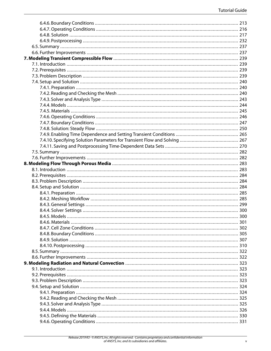
Chapter 7: Modeling Transient Compressible Flow
7.1. Introduction
7.2. Prerequisites
7.3. Problem Description
7.4. Setup and Solution
7.4.1. Preparation
7.4.2. Reading and Checking the Mesh
7.4.3. Solver and Analysis Type
7.4.4. Models
7.4.5. Materials
7.4.6. Operating Conditions
7.4.7. Boundary Conditions
7.4.8. Solution: Steady Flow
7.4.9. Enabling Time Dependence and Setting Transient Conditions
7.4.10. Specifying Solution Parameters for Transient Flow and Solving
7.4.11. Saving and Postprocessing Time-Dependent Data Sets
7.5. Summary
7.6. Further Improvements
Chapter 8: Modeling Flow Through Porous Media
8.1. Introduction
8.2. Prerequisites
8.3. Problem Description
8.4. Setup and Solution
8.4.1. Preparation
8.4.2. Meshing Workflow
8.4.3. General Settings
8.4.4. Solver Settings
8.4.5. Models
8.4.6. Materials
8.4.7. Cell Zone Conditions
8.4.8. Boundary Conditions
8.4.9. Solution
8.4.10. Postprocessing
8.5. Summary
8.6. Further Improvements
Chapter 9: Modeling Radiation and Natural Convection
9.1. Introduction
9.2. Prerequisites
9.3. Problem Description
9.4. Setup and Solution
9.4.1. Preparation
9.4.2. Reading and Checking the Mesh
9.4.3. Solver and Analysis Type
9.4.4. Models
9.4.5. Defining the Materials
9.4.6. Operating Conditions
9.4.7. Boundary Conditions
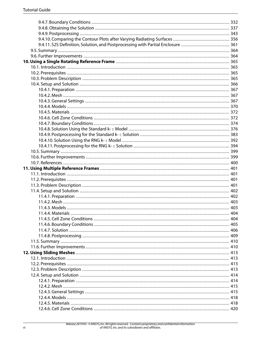
9.4.8. Obtaining the Solution
9.4.9. Postprocessing
9.4.10. Comparing the Contour Plots after Varying Radiating Surfaces
9.4.11. S2S Definition, Solution, and Postprocessing with Partial Enclosure
9.5. Summary
9.6. Further Improvements
Chapter 10: Using a Single Rotating Reference Frame
10.1. Introduction
10.2. Prerequisites
10.3. Problem Description
10.4. Setup and Solution
10.4.1. Preparation
10.4.2. Mesh
10.4.3. General Settings
10.4.4. Models
10.4.5. Materials
10.4.6. Cell Zone Conditions
10.4.7. Boundary Conditions
10.4.8. Solution Using the Standard k- ε Model
10.4.9. Postprocessing for the Standard k- ε Solution
10.4.10. Solution Using the RNG k- ε Model
10.4.11. Postprocessing for the RNG k- ε Solution
10.5. Summary
10.6. Further Improvements
10.7. References
Chapter 11: Using Multiple Reference Frames
11.1. Introduction
11.2. Prerequisites
11.3. Problem Description
11.4. Setup and Solution
11.4.1. Preparation
11.4.2. Mesh
11.4.3. Models
11.4.4. Materials
11.4.5. Cell Zone Conditions
11.4.6. Boundary Conditions
11.4.7. Solution
11.4.8. Postprocessing
11.5. Summary
11.6. Further Improvements
Chapter 12: Using Sliding Meshes
12.1. Introduction
12.2. Prerequisites
12.3. Problem Description
12.4. Setup and Solution
12.4.1. Preparation
12.4.2. Mesh
12.4.3. General Settings
12.4.4. Models
12.4.5. Materials
12.4.6. Cell Zone Conditions
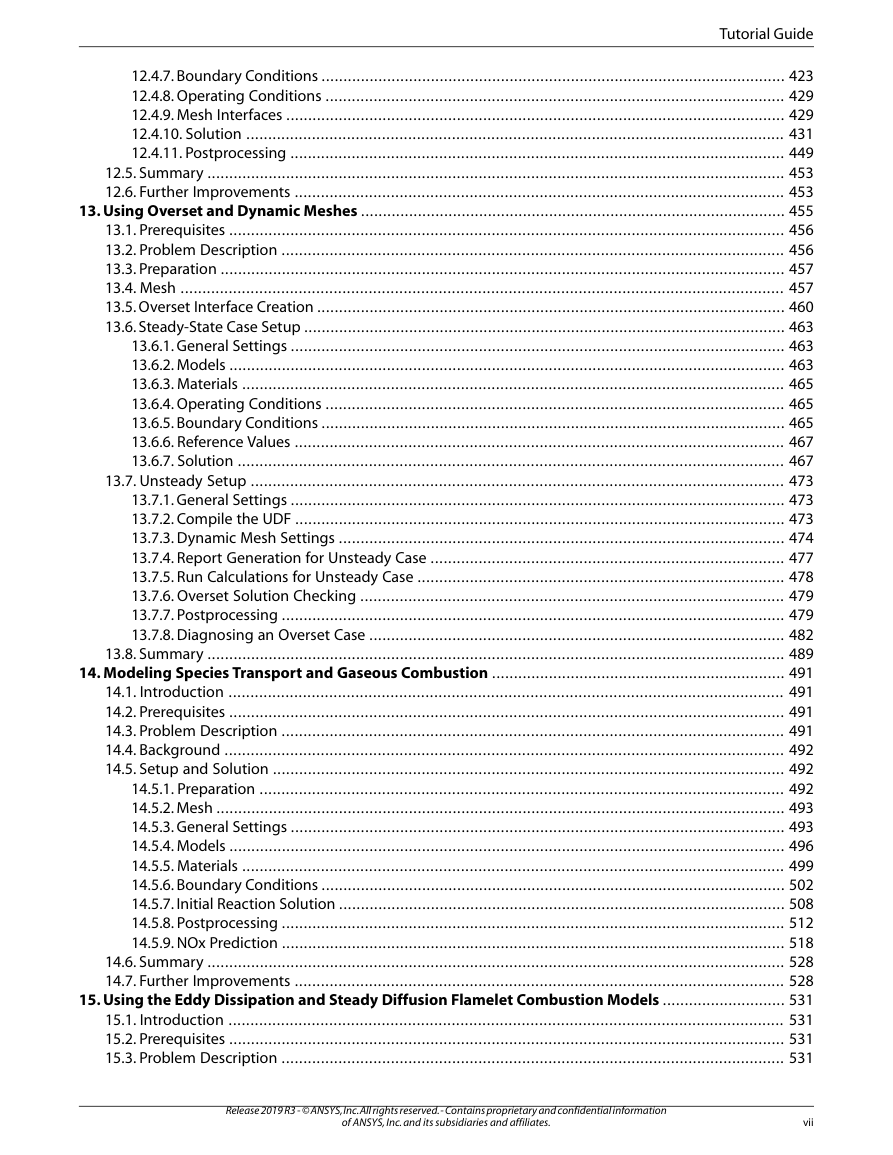
12.4.7. Boundary Conditions
12.4.8. Operating Conditions
12.4.9. Mesh Interfaces
12.4.10. Solution
12.4.11. Postprocessing
12.5. Summary
12.6. Further Improvements
Chapter 13: Using Overset and Dynamic Meshes
13.1. Prerequisites
13.2. Problem Description
13.3. Preparation
13.4. Mesh
13.5. Overset Interface Creation
13.6. Steady-State Case Setup
13.6.1. General Settings
13.6.2. Models
13.6.3. Materials
13.6.4. Operating Conditions
13.6.5. Boundary Conditions
13.6.6. Reference Values
13.6.7. Solution
13.7. Unsteady Setup
13.7.1. General Settings
13.7.2. Compile the UDF
13.7.3. Dynamic Mesh Settings
13.7.4. Report Generation for Unsteady Case
13.7.5. Run Calculations for Unsteady Case
13.7.6. Overset Solution Checking
13.7.7. Postprocessing
13.7.8. Diagnosing an Overset Case
13.8. Summary
Chapter 14: Modeling Species Transport and Gaseous Combustion
14.1. Introduction
14.2. Prerequisites
14.3. Problem Description
14.4. Background
14.5. Setup and Solution
14.5.1. Preparation
14.5.2. Mesh
14.5.3. General Settings
14.5.4. Models
14.5.5. Materials
14.5.6. Boundary Conditions
14.5.7. Initial Reaction Solution
14.5.8. Postprocessing
14.5.9. NOx Prediction
14.6. Summary
14.7. Further Improvements
Chapter 15: Using the Eddy Dissipation and Steady Diffusion Flamelet Combustion Models
15.1. Introduction
15.2. Prerequisites
15.3. Problem Description
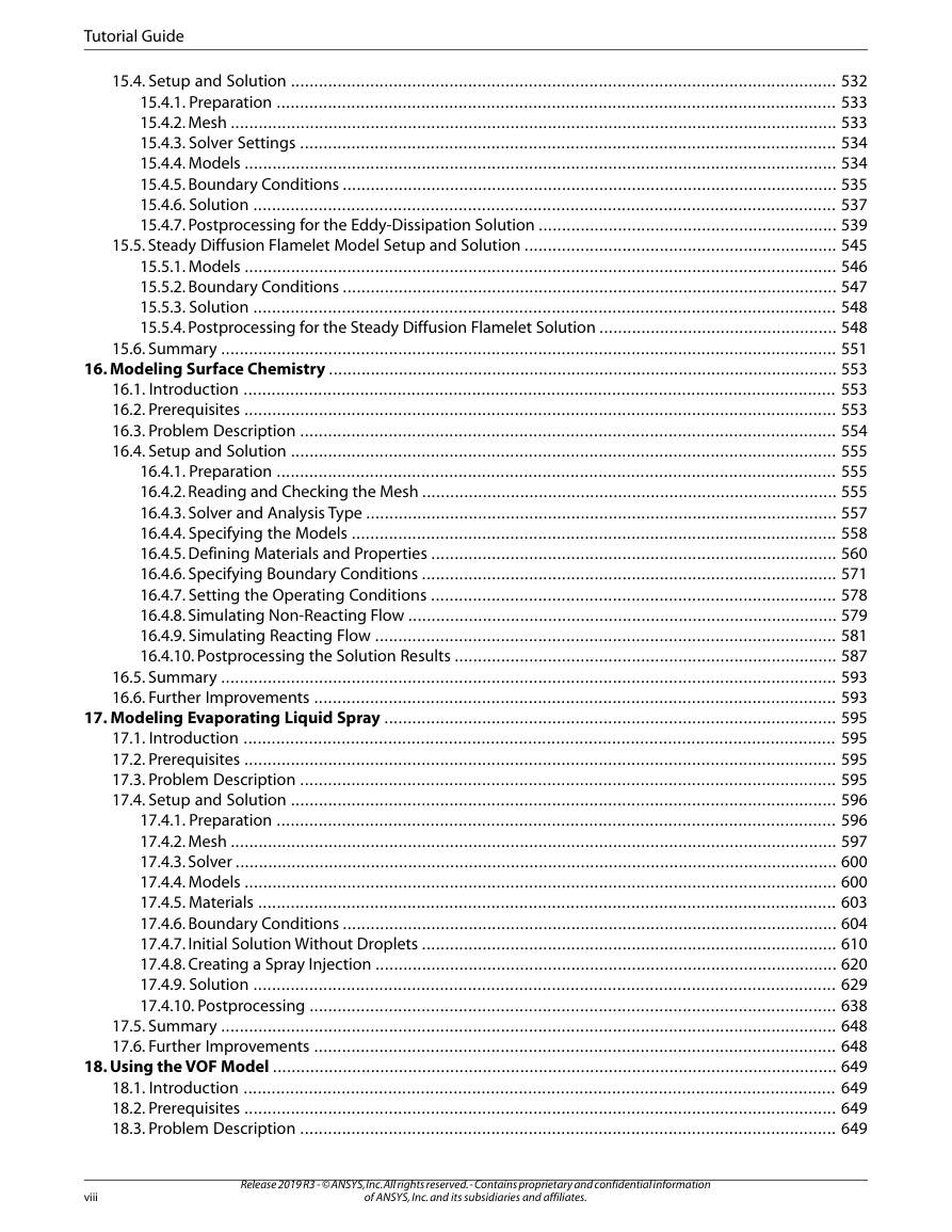
15.4. Setup and Solution
15.4.1. Preparation
15.4.2. Mesh
15.4.3. Solver Settings
15.4.4. Models
15.4.5. Boundary Conditions
15.4.6. Solution
15.4.7. Postprocessing for the Eddy-Dissipation Solution
15.5. Steady Diffusion Flamelet Model Setup and Solution
15.5.1. Models
15.5.2. Boundary Conditions
15.5.3. Solution
15.5.4. Postprocessing for the Steady Diffusion Flamelet Solution
15.6. Summary
Chapter 16: Modeling Surface Chemistry
16.1. Introduction
16.2. Prerequisites
16.3. Problem Description
16.4. Setup and Solution
16.4.1. Preparation
16.4.2. Reading and Checking the Mesh
16.4.3. Solver and Analysis Type
16.4.4. Specifying the Models
16.4.5. Defining Materials and Properties
16.4.6. Specifying Boundary Conditions
16.4.7. Setting the Operating Conditions
16.4.8. Simulating Non-Reacting Flow
16.4.9. Simulating Reacting Flow
16.4.10. Postprocessing the Solution Results
16.5. Summary
16.6. Further Improvements
Chapter 17: Modeling Evaporating Liquid Spray
17.1. Introduction
17.2. Prerequisites
17.3. Problem Description
17.4. Setup and Solution
17.4.1. Preparation
17.4.2. Mesh
17.4.3. Solver
17.4.4. Models
17.4.5. Materials
17.4.6. Boundary Conditions
17.4.7. Initial Solution Without Droplets
17.4.8. Creating a Spray Injection
17.4.9. Solution
17.4.10. Postprocessing
17.5. Summary
17.6. Further Improvements
Chapter 18: Using the VOF Model
18.1. Introduction
18.2. Prerequisites
18.3. Problem Description
18.4. Setup and Solution
18.4.1. Preparation
18.4.2. Reading and Manipulating the Mesh
18.4.3. General Settings
18.4.4. Models
18.4.5. Materials
18.4.6. Phases
18.4.7. Operating Conditions
18.4.8. Boundary Conditions
18.4.9. Solution
18.4.10. Postprocessing
18.5. Summary
18.6. Further Improvements
Chapter 19: Modeling Cavitation
19.1. Introduction
19.2. Prerequisites
19.3. Problem Description
19.4. Setup and Solution
19.4.1. Preparation
19.4.2. Reading and Checking the Mesh
19.4.3. Solver Settings
19.4.4. Models
19.4.5. Materials
19.4.6. Phases
19.4.7. Boundary Conditions
19.4.8. Operating Conditions
19.4.9. Solution
19.4.10. Postprocessing
19.5. Summary
19.6. Further Improvements
Chapter 20: Using the Multiphase Models
20.1. Introduction
20.2. Prerequisites
20.3. Problem Description
20.4. Setup and Solution
20.4.1. Preparation
20.4.2. Mesh
20.4.3. Solver Settings
20.4.4. Models
20.4.5. Materials
20.4.6. Phases
20.4.7. Cell Zone Conditions
20.4.8. Boundary Conditions
20.4.9. Solution
20.4.10. Postprocessing
20.5. Summary
Chapter 21: Modeling Solidification
21.1. Introduction
21.2. Prerequisites
21.3. Problem Description
21.4. Setup and Solution
21.4.1. Preparation
21.4.2. Reading and Checking the Mesh
21.4.3. Specifying Solver and Analysis Type
21.4.4. Specifying the Models
21.4.5. Defining Materials
21.4.6. Setting the Cell Zone Conditions
21.4.7. Setting the Boundary Conditions
21.4.8. Solution: Steady Conduction
21.4.9. Solution: Transient Flow and Heat Transfer
21.5. Summary
21.6. Further Improvements
Chapter 22: Using the Eulerian Granular Multiphase Model with Heat Transfer
22.1. Introduction
22.2. Prerequisites
22.3. Problem Description
22.4. Setup and Solution
22.4.1. Preparation
22.4.2. Mesh
22.4.3. Solver Settings
22.4.4. Models
22.4.5. UDF
22.4.6. Materials
22.4.7. Phases
22.4.8. Boundary Conditions
22.4.9. Solution
22.4.10. Postprocessing
22.5. Summary
22.6. Further Improvements
22.7. References
Chapter 23: Modeling One-Way Fluid-Structure Interaction (FSI) Within Fluent
23.1. Introduction
23.2. Prerequisites
23.3. Problem Description
23.4. Setup and Solution
23.4.1. Preparation
23.4.2. Structural Model
23.4.3. Materials
23.4.4. Cell Zone Conditions
23.4.5. Boundary Conditions
23.4.6. Solution
23.4.7. Postprocessing
23.5. Summary
Chapter 24: Modeling Two-Way Fluid-Structure Interaction (FSI) Within Fluent
24.1. Introduction
24.2. Prerequisites
24.3. Problem Description
24.4. Setup and Solution
24.4.1. Preparation
24.4.2. Solver and Analysis Type
24.4.3. Structural Model
24.4.4. Materials
24.4.5. Cell Zone Conditions
24.4.6. Boundary Conditions
24.4.7. Dynamic Mesh Zones
24.4.8. Solution Animations
24.4.9. Solution
24.4.10. Postprocessing
24.5. Summary
Chapter 25: Using the Adjoint Solver – 2D Laminar Flow Past a Cylinder
25.1. Introduction
25.2. Prerequisites
25.3. Problem Description
25.4. Setup and Solution
25.4.1. Step 1: Preparation
25.4.2. Step 2: Define Observables
25.4.3. Step 3: Compute the Drag Sensitivity
25.4.4. Step 4: Postprocess and Export Drag Sensitivity
25.4.4.1. Boundary Condition Sensitivity
25.4.4.2. Momentum Source Sensitivity
25.4.4.3. Shape Sensitivity
25.4.4.4. Exporting Drag Sensitivity Data
25.4.5. Step 5: Compute Lift Sensitivity
25.4.6. Step 6: Modify the Shape
25.5. Summary
Chapter 26: Simulating a Single Battery Cell Using the MSMD Battery Model
26.1. Introduction
26.2. Prerequisites
26.3. Problem Description
26.4. Setup and Solution
26.4.1. Preparation
26.4.2. Reading and Scaling the Mesh
26.4.3. Loading the MSMD battery Add-on
26.4.4. NTGK Battery Model Setup
26.4.4.1. Specifying Solver and Models
26.4.4.2. Defining New Materials for Cell and Tabs
26.4.4.3. Defining Cell Zone Conditions
26.4.4.4. Defining Boundary Conditions
26.4.4.5. Specifying Solution Settings
26.4.4.6. Obtaining Solution
26.4.5. Postprocessing
26.4.6. Simulating the Battery Pulse Discharge Using the ECM Model
26.4.7. Using the Reduced Order Method (ROM)
26.4.8. External and Internal Short-Circuit Treatment
26.4.8.1. Setting up and Solving a Short-Circuit Problem
26.4.8.2. Postprocessing
26.5. Summary
26.6. Appendix
26.7. References
Chapter 27: Simulating a 1P3S Battery Pack Using the MSMD Battery Model
27.1. Introduction
27.2. Prerequisites
27.3. Problem Description
27.4. Setup and Solution
27.4.1. Preparation
27.4.2. Reading and Scaling the Mesh
27.4.3. Loading the MSMD battery Add-on
27.4.4. Battery Model Setup
27.4.4.1. Specifying Solver and Models
27.4.4.2. Defining New Materials
27.4.4.3. Defining Cell Zone Conditions
27.4.4.4. Defining Boundary Conditions
27.4.4.5. Specifying Solution Settings
27.4.4.6. Obtaining Solution
27.4.5. Postprocessing
27.5. Summary
Chapter 28: In-Flight Icing Tutorial Using Fluent Icing
28.1. Fluent Airflow on the NACA0012 Airfoil
28.2. Flow Solution on the Rough NACA0012 Airfoil
28.3. Droplet Impingement on the NACA0012
28.3.1. Monodispersed Calculation
28.3.2. Langmuir-D Distribution
28.3.3. Post-Processing Using Quick-View
28.4. Fluent Icing Ice Accretion on the NACA0012
28.5. Postprocessing an Ice Accretion Solution Using CFD-Post Macros
28.6. Multi-Shot Ice Accretion with Automatic Mesh Displacement
28.7. Multi-Shot Ice Accretion with Automatic Mesh Displacement – Postprocessing Using CFD-Post


 2023年江西萍乡中考道德与法治真题及答案.doc
 2012年重庆南川中考生物真题及答案.doc
 2013年江西师范大学地理学综合及文艺理论基础考研真题.doc
 2020年四川甘孜小升初语文真题及答案I卷.doc
 2020年注册岩土工程师专业基础考试真题及答案.doc
 2023-2024学年福建省厦门市九年级上学期数学月考试题及答案.doc
 2021-2022学年辽宁省沈阳市大东区九年级上学期语文期末试题及答案.doc
 2022-2023学年北京东城区初三第一学期物理期末试卷及答案.doc
 2018上半年江西教师资格初中地理学科知识与教学能力真题及答案.doc
 2012年河北国家公务员申论考试真题及答案-省级.doc
 2020-2021学年江苏省扬州市江都区邵樊片九年级上学期数学第一次质量检测试题及答案.doc
 2022下半年黑龙江教师资格证中学综合素质真题及答案.doc