MR Configurator2 Version1
MODEL
SW1DNC-MRC2-E
INSTALLATION GUIDE
Thank you for choosing the MELSOFT MR Configurator2.
To optimize the use of the MR Configurator2, please read over this
Installation Guide and the corresponding AC servo Installation Guide before
using the software. After reading the Installation Guide, always place
this Installation Guide in a safe place.
B
�
Safety Instructions
(Always read these instructions before using the equipment.)
Do not attempt to install, operate, maintain or inspect the servo amplifier and servo motor until you have read
through this Installation Guide, and appended documents carefully and can use the equipment correctly. Do
not use the servo amplifier and servo motor until you have a full knowledge of the equipment, safety
information and instructions.
In this Installation Guide, the safety instruction levels are classified into "WARNING" and "CAUTION".
WARNING
CAUTION
Indicates that incorrect handling may cause hazardous conditions,
resulting in death or severe injury.
Indicates that incorrect handling may cause hazardous conditions,
resulting in medium or slight injury to personnel or may cause physical
damage.
Note that the CAUTION level may lead to a serious consequence according to conditions. Please follow the
instructions of both levels because they are important to personnel safety.
What must not be done and what must be done are indicated by the following diagrammatic symbols:
: Indicates what must not be done. For example, "No Fire" is indicated by
: Indicates what must be done. For example, grounding is indicated by
.
.
In this Installation Guide, instructions at a lower level than the above, instructions for other functions, and so on
are classified into "POINT".
After reading this Installation Guide, always keep it accessible to the operator.
Windows is a trademark of Microsoft Corporation.
The "Mitsubishi general-purpose AC servo MELSOFT MR Configurator2" is a production of Mitsubishi
Electric Corporation. Mitsubishi Electric Corporation reserves the copyright and all other rights of this
software.
This Installation Guide may not be reproduced or copied, in whole or part, without written consent of
Mitsubishi Electric Corporation.
All other company and product names contained in this Installation Guide are registered trademarks or
trademarks of their respective companies.
CAUTION
Before executing the test mode, always read section 2.3 "Precaution for test
mode".
A - 1
�
MEMO
A - 2
�
CONTENTS
1. INTRODUCTION
1 - 1 to 1 -15
1.1 Specifications ........................................................................................................................................... 1 - 1
1.2 System configuration ............................................................................................................................... 1 - 4
1.2.1 Components ...................................................................................................................................... 1 - 4
1.2.2 Configuration ..................................................................................................................................... 1 - 5
1.3 Basic terms............................................................................................................................................... 1 - 8
1.4 Installation procedure............................................................................................................................... 1 - 9
1.5 New hardware detection wizard .............................................................................................................1 -13
2. HOW TO USE THE SOFTWARE
2 - 1 to 2 -12
2.1 Operation.................................................................................................................................................. 2 - 1
2.1.1 Start-up.............................................................................................................................................. 2 - 1
2.1.2 Project................................................................................................................................................ 2 - 1
2.2 Commands and display windows............................................................................................................ 2 - 5
2.3 Precautions for test mode........................................................................................................................ 2 - 8
2.4 Simple language for program operation................................................................................................2 - 10
2.4.1 Language.........................................................................................................................................2 - 10
2.4.2 Program example............................................................................................................................2 - 11
2.4.3 Instruction ........................................................................................................................................2 - 11
3. TROUBLESHOOTING
3 - 1 to 3 - 2
1
�
MEMO
2
�
1. INTRODUCTION
1. INTRODUCTION
1.1 Specifications
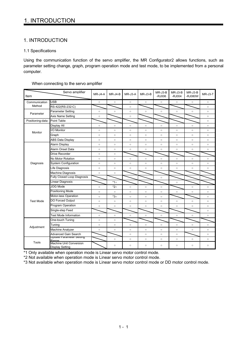
Using the communication function of the servo amplifier, the MR Configurator2 allows functions, such as
parameter setting change, graph, program operation mode and test mode, to be implemented from a personal
computer.
When connecting to the servo amplifier
Servo amplifier
MR-J4-A MR-J4-B MR-J3-A MR-J3-B MR-J3-B
-RJ006
MR-J3-B
-RJ004
MR-J3-B
-RJ080W MR-J3-T
Item
Communication
Method
Parameter
USB
RS-422(RS-232-C)
Parameter Setting
Axis Name Setting
Monitor
Diagnosis
Positioning-data Point Table
Display All
I/O Monitor
Graph
ABS Data Display
Alarm Display
Alarm Onset Data
Drive Recorder
No Motor Rotation
System Configuration
Life Diagnosis
Machine Diagnosis
Fully Closed Loop Diagnosis
Linear Diagnosis
JOG Mode
Positioning Mode
Motor-less Operation
DO Forced Output
Program Operation
Single-step Feed
Test Mode Information
One-touch Tuning
Tuning
Machine Analyzer
Advanced Gain Search
Update Parameter Setting
Range
Machine Unit Conversion
Display Setting
Adjustment
Test Mode
Tools
○
○
○
○
○
○
○
○
○
○
○
○
○
○
○
○
○
○
○
○
○
○
○
○
○
○
○
○
○
○
○
○
○
○
○
○
*1○
*2○
○
*3○
○
○
○
○
○
○
○
○
○
○
○
○
○
○
○
○
○
○
○
○
○
○
○
○
○
○
○
○
○
○
○
○
○
○
○
○
○
○
○
○
○
○
○
○
○
○
○
○
○
○
○
○
○
○
○
○
○
○
○
○
○
○
○
○
○
○
○
○
○
○
○
○
○
○
○
○
○
○
○
○
○
○
○
○
○
○
○
○
○
○
○
○
○
○
○
○
○
○
○
○
○
○
○
○
○
○
○
○
○
○
○
○
○
○
○
○
○
○
○
○
○
○
○
○
○
○
○
○
○
○
○
○
○
○
○
○
○
○
○
○
○
○
○
○
*1 Only available when operation mode is Linear servo motor control mode.
*2 Not available when operation mode is Linear servo motor control mode.
*3 Not available when operation mode is Linear servo motor control mode or DD motor control mode.
1 - 1
�
1. INTRODUCTION
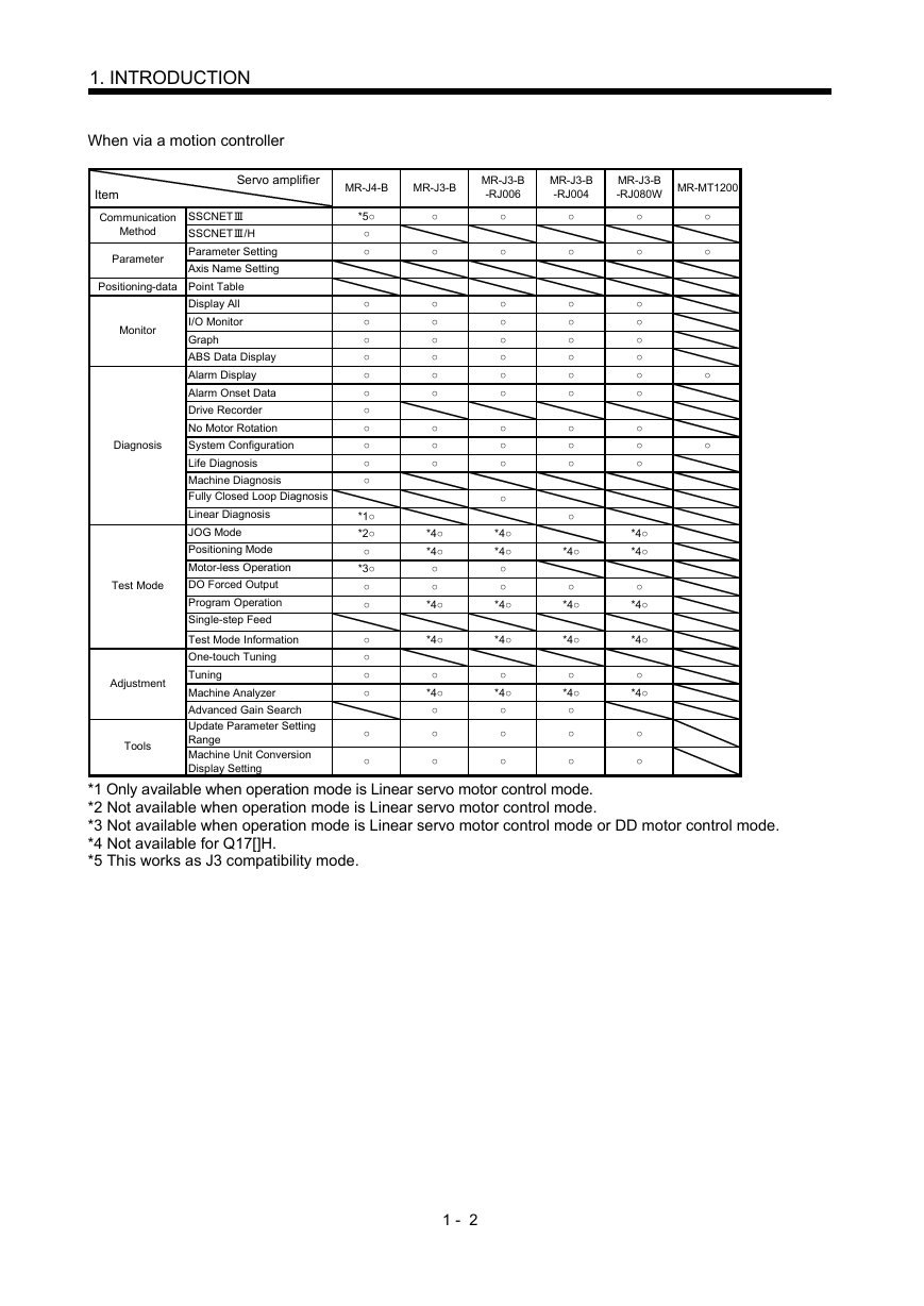
When via a motion controller
Servo amplifier
MR-J4-B
MR-J3-B
MR-J3-B
-RJ006
MR-J3-B
-RJ004
MR-J3-B
-RJ080W MR-MT1200
Item
Communication
Method
Parameter
SSCNETⅢ
SSCNETⅢ/H
Parameter Setting
Axis Name Setting
Monitor
Diagnosis
Positioning-data Point Table
Display All
I/O Monitor
Graph
ABS Data Display
Alarm Display
Alarm Onset Data
Drive Recorder
No Motor Rotation
System Configuration
Life Diagnosis
Machine Diagnosis
Fully Closed Loop Diagnosis
Linear Diagnosis
JOG Mode
Positioning Mode
Motor-less Operation
DO Forced Output
Program Operation
Single-step Feed
Test Mode Information
One-touch Tuning
Tuning
Machine Analyzer
Advanced Gain Search
Update Parameter Setting
Range
Machine Unit Conversion
Display Setting
Adjustment
Test Mode
Tools
○
○
○
○
*5○
○
○
○
○
○
○
○
○
○
○
○
○
○
*1○
*2○
○
*3○
○
○
○
○
○
○
○
○
○
○
○
○
○
○
○
○
○
○
○
*4○
*4○
○
○
*4○
*4○
○
*4○
○
○
○
○
○
○
○
○
○
○
○
○
○
○
○
*4○
*4○
○
○
*4○
*4○
○
*4○
○
○
○
○
○
○
○
○
○
○
○
○
○
○
○
*4○
○
*4○
*4○
○
*4○
○
○
○
○
○
○
○
○
○
○
○
○
○
○
*4○
*4○
○
*4○
*4○
○
*4○
○
○
*1 Only available when operation mode is Linear servo motor control mode.
*2 Not available when operation mode is Linear servo motor control mode.
*3 Not available when operation mode is Linear servo motor control mode or DD motor control mode.
*4 Not available for Q17[]H.
*5 This works as J3 compatibility mode.
1 - 2
�
1. INTRODUCTION
When via a simple motion
Servo amplifier
MR-J4-B
MR-J3-B
MR-J3-B
-RJ006
MR-J3-B
-RJ004
MR-J3-B
-RJ080W MR-MT1200
Item
Communication
Method
Parameter
SSCNETⅢ
SSCNETⅢ/H
Parameter Setting
Axis Name Setting
Monitor
Diagnosis
Positioning-data Point Table
Display All
I/O Monitor
Graph
ABS Data Display
Alarm Display
Alarm Onset Data
Drive Recorder
No Motor Rotation
System Configuration
Life Diagnosis
Machine Diagnosis
Fully Closed Loop Diagnosis
Linear Diagnosis
JOG Mode
Positioning Mode
Motor-less Operation
DO Forced Output
Program Operation
Single-step Feed
Test Mode Information
One-touch Tuning
Tuning
Machine Analyzer
Advanced Gain Search
Update Parameter Setting
Range
Machine Unit Conversion
Display Setting
Adjustment
Test Mode
Tools
*5○
○
○
○
○
○
○
○
○
○
○
○
○
○
*1○
*2○
○
*3○
○
○
○
○
○
○
○
○
○
*6○
○
*6○
○
*6○
○
*6○
○
*6○
○
○
○
○
○
○
○
○
○
○
○
○
○
○
○
○
○
○
○
○
○
○
○
○
○
○
○
○
○
○
○
○
○
○
○
○
○
○
○
○
○
○
○
○
○
○
○
○
○
○
○
○
○
○
○
○
○
○
*1 Only available when operation mode is Linear servo motor control mode.
*2 Not available when operation mode is Linear servo motor control mode.
*3 Not available when operation mode is Linear servo motor control mode or DD motor control mode.
*5 This works as J3 compatibility mode.
*6 Not available for online setting. Please read/write parameters using GX Works2.
1 - 3
�




 2023年江西萍乡中考道德与法治真题及答案.doc
 2012年重庆南川中考生物真题及答案.doc
 2013年江西师范大学地理学综合及文艺理论基础考研真题.doc
 2020年四川甘孜小升初语文真题及答案I卷.doc
 2020年注册岩土工程师专业基础考试真题及答案.doc
 2023-2024学年福建省厦门市九年级上学期数学月考试题及答案.doc
 2021-2022学年辽宁省沈阳市大东区九年级上学期语文期末试题及答案.doc
 2022-2023学年北京东城区初三第一学期物理期末试卷及答案.doc
 2018上半年江西教师资格初中地理学科知识与教学能力真题及答案.doc
 2012年河北国家公务员申论考试真题及答案-省级.doc
 2020-2021学年江苏省扬州市江都区邵樊片九年级上学期数学第一次质量检测试题及答案.doc
 2022下半年黑龙江教师资格证中学综合素质真题及答案.doc