logo资料库

EB Propsim F8 用户说明书.pdf

第1页 / 共280页
第2页 / 共280页
第3页 / 共280页
第4页 / 共280页
第5页 / 共280页
第6页 / 共280页
第7页 / 共280页
第8页 / 共280页
资料共280页,剩余部分请下载后查看
EB Propsim F8 User Reference
Notice
Warranty
Abbreviations
1 Introduction
1.1 EB Propsim F8
1.1.1 Channel emulation concept
1.1.2 Physical connectors and LEDs
1.1.3 EB Propsim F8 views and applications
2 Product Specification
2.1 Applications
2.2 Product configuration items
2.3 Definitions and requirements
2.3.1 Definitions
2.3.2 Conditions required to meet specifications
2.3.3 Test setup
2.4 Electrical specifications
2.4.1 Power supply
2.4.2 Absolute maximum ratings
2.4.3 Emulator block diagram
2.4.4 Physical connectors and LEDs
2.4.5 Rear panel
2.4.6 User control interfaces
2.4.7 RF characteristics
2.4.8 Fading channel emulation
2.4.9 Multi-emulator synchronization
2.4.10 Optional feature: Shadowing
2.4.11 Optional feature: Internal Interference Generator
2.4.12 Optional feature: Aerospace and Satellite Option
2.4.13 Optional feature: Internal RF Local Oscillator
2.5 External equipment
2.5.1 PC accessories
2.5.2 External RF local
2.6 OS and pre-installed 3rd party applications
2.6.1 The security and virus protection of the operating system
2.6.2 User installations
2.7 Emulation channel topologies
2.8 Mechanical specifications
2.9 Environmental and safety specifications
2.9.1 Environmental and climatic requirements (operating)
2.9.2 Transportation requirements
2.9.3 Electrical safety regulations
2.9.4 Electromagnetic compatibility (EMC)
2.9.5 Compatible standards and regulations
3 Graphical User Interface
3.1 Navigation bar
3.2 Menus and Toolbar
3.3 Running view
3.3.1 Running view toolbar
3.3.2 Running view menus
3.3.3 Emulation Settings view
3.3.4 CIR Graphics view
3.4 Editing view
3.4.1 Editing view toolbar
3.4.2 Editing view menus
3.4.3 Emulation block diagram
3.4.4 Settings
3.5 Channel model view
3.5.1 Channel model view toolbar
3.5.2 Channel model view menus
3.5.3 Channel Impulse Response Graph
3.5.4 Channel model settings – Model parameters
3.5.5 Channel model settings – Taps
3.6 Correlation Editor
3.6.1 Editing the correlation coefficients
3.6.2 Correlation Editor in MIMO mode
3.7 Emulation Batch Builder
3.7.1 Usage
3.8 Multi Emulator Scaler
3.8.1 Using scaler tool
3.9 User profiles
3.9.1 Create New User
3.9.2 Change User
3.9.3 Delete User
3.10 System Configuration
3.11 Restart/Shutdown
4 Shadowing (optional feature)
4.1 Shadowing profiles
4.1.1 Lognormal shadowing profile
4.1.2 Sawtooth shadowing profile
4.1.3 Sinusoidal shadowing profile
4.1.4 Triangle shadowing profile
4.1.5 User defined shadowing profile
5 Internal Interference Generator (optional feature)
5.1 Interference settings
5.1.1 General interference settings
5.1.2 AWGN settings
5.1.3 Filtered AWGN settings
5.1.4 CW settings
6 Aerospace and Satellite Option – ASO (optional feature)
6.1 Aerospace Model Editor
6.1.1 File menu
6.1.2 Model Information
6.1.3 Graphical Views
6.1.4 Model preview
6.1.5 New Model Generation Wizard
6.1.6 Editing existing Aerospace models
6.1.7 Partial models
6.2 Creating and Running Emulation
6.2.1 Creating Aerospace emulation in Editing View
6.2.2 Running Aerospace emulation
7 Remote Control
7.1 GPIB
7.2 LAN
7.2.1 LAN Example
7.2.2 LAN Example using Microsoft Visual Studio
7.3 ATE monitor interface
7.3.2 Error window
7.3.3 ATE monitor display
7.4 ATE command syntax
7.4.1 Common syntax
7.4.2 Interface specific syntax
7.5 ATE command interface
7.5.1 Common commands
7.5.2 System commands
7.5.3 Emulation Control
7.5.4 Channel Input Settings
7.5.5 Channel Output Settings
7.5.6 Channel Settings
7.5.7 Internal Interference Generator control (Optional)
7.5.8 Channel Model Information
7.5.9 Signal routing
7.5.10 RF Local Source (Internal Local Oscillator) control
7.5.11 External Trigger
7.5.12 Multiple emulations loading
7.5.13 Multi-emulator synchronization
7.5.14 Example script
7.6 Errors and events
7.6.1 Command error
7.6.2 Execution error
7.6.3 Device-specific error
7.6.4 Error/Event queue overflow
7.6.5 Communication error
7.6.6 Query error
7.7 Troubleshooting
7.7.1 Failure handling
8 File Formats
8.1 .ASC File
8.1.1 Header
8.1.2 Tap data
8.2 .ASO File
8.2.1 Function based .ASO file
8.2.2 Coordinate based .ASO file
8.2.3 Arbitrary .ASO file
8.2.4 File syntax
8.3 .ICS File
8.3.1 [Model] Section
8.3.2 [Sequence] Section
8.3.3 [Tap] Section
8.4 .IR File
8.4.1 Syntax
8.5 .MAT file
8.5.1 Required variables
8.5.2 Optional variables
8.5.3 MAT file example
9 Maintenance
9.1 Warranty
9.2 Calibration and service
9.3 Connectors and cables
9.4 Cleaning
9.5 Over current protector
9.6 Assistance
10 Troubleshooting
10.1 Typical problems
10.1.1 Emulator does not start
10.1.2 Self test fails
10.1.3 No signal at the emulator output
10.1.4 Status led is red
10.1.5 Power led is red
10.1.6 RF channel status led is red
10.1.7 Incorrect signal level
10.1.8 Incorrect test results
10.2 Error and warning messages
10.2.1 Running view errors
10.2.2 Editing view errors
10.2.3 Channel model view errors
10.2.4 Correlation editor errors
10.2.5 ATE Command specific warnings
11 Wireless propagation environment
11.1 Radio wave propagation
11.2 Shadowing
11.3 Multipath propagation
11.4 Factors affecting overall attenuation
11.5 Doppler effect
11.6 Noise and interference
11.7 Multi-antenna solutions
11.7.1 Selection diversity
11.7.2 Spatial multiplexing
11.8 Radio channel measurements
11.8.1 Channel impulse response
11.8.2 Frequency response
11.9 Channel modeling
11.9.1 Standard models
11.9.2 Custom models
11.9.3 Multichannel models
11.10 References
EB Propsim F8 User Reference
EB Propsim F8 Radio Channel Emulator User Reference Release 1.4 Document version 1.3  Copyright 2011 Elektrobit (EB) All Rights Reserved Printed in Finland
EB PROPSIM F8 REL 1.4 This product is covered by at least by one of the following patents and patent applications: US 7054781, US 7184720, US 7394880, US 11/266,599, EP 1371160, EP 1393476, EP 1449316, EP 04733006.3, FI 111206, FI 113313, FI 113427, FI 116432, JP 3730961, JP 4046609, JP 4317874, KR 10-0851723, KR 10-0857678, ZL 02800418.3, CN 02805107.6 Published by: Elektrobit System Test Ltd. Tutkijantie 8, FI-90590 OULU FINLAND Telephone: Int. +358 40 344 2000 Fax: Int. +358 8 343 032 Email: wct.support@elektrobit.com http://www.elektrobit.com Copyright 2011 Elektrobit (EB). All rights reserved. The information contained herein is subject to change without notice. EB retains ownership of and all other rights to the material expressed in this document. Any reproduction of the content of this document without prior written permission from EB is prohibited. 2 USER REFERENCE
EB PROPSIM F8 REL 1.4 EB website at www.elektrobit.com The EB website holds the latest news and information on a wide range of subjects related to the EB Propsim product family and test equipment for wireless communications. In EB Extranet and support site, you can find information on your product and other EB Propsim radio channel emulators. The site also offers you download possibilities and the most convenient way to contact your EB Propsim support. EB Extranet and support site can be accessed at: http://www.elektrobit.com/ebpropsimextranet. USER REFERENCE 3
EB PROPSIM F8 REL 1.4 Notice Elektrobit System Test Ltd. reserves the right to change its products and the information in this document without notice due to continuous improvement and development. Elektrobit System Test Ltd. makes no warranty of any kind with regard to this material, including, but not limited to, the implied warranties of merchantability or fitness for a particular purpose. Elektrobit System Test Ltd. shall not be liable for errors contained herein or for damages in connection with the furnishing, performance, or use of this material. Warranty Elektrobit System Test Ltd. warrants that this product will be free from defects in materials and workmanship for a period of one year from the date of shipment. During the warranty period, Elektrobit System Test Ltd. will, at its option, either repair or replace products that prove to be defective. For obtaining service under this warranty, the Buyer must notify Elektrobit System Test Ltd. of the defect before the expiration of the warranty period and make suitable arrangements for the performance of service. The expenses associated to shipping the product to the service center and back to Buyer will be paid by Elektrobit System Test Ltd. Elektrobit System Test Ltd. warrants that its software and firmware designated for use with an instrument will execute its programming instructions when properly installed on that instrument. Elektrobit System Test Ltd. does not warrant that the operation of the instrument, or software, or firmware will be uninterrupted or error-free. Limitation of Warranty This warranty shall not apply to defects, failures or damages resulting from improper or inadequate maintenance and care, Buyer-supplied software or interfacing, unauthorized modification or misuse, operation outside of the environmental specifications for the product, or improper site preparation or maintenance. NO OTHER WARRANTY IS EXPRESSED OR IMPLIED. ELEKTROBIT SYSTEM TEST LTD DISCLAIMS ANY IMPLIED WARRANTIES OF MERCHANTABILITY AND FITNESS FOR A PARTICULAR PURPOSE. ELEKTROBIT SYSTEM TEST LTD’S RESPONSIBILITY TO REPAIR OR REPLACE DEFECTIVE PRODUCTS IS THE SOLE AND EXCLUSIVE REMEDY PROVIDED TO THE BUYER. ELEKTROBIT SYSTEM TEST LTD SHALL NOT BE LIABLE FOR ANY DIRECT, INDIRECT, SPECIAL, INCIDENTAL, OR CONSEQUENTIAL DAMAGES, WHETHER BASED ON CONTRACT, TORT, OR ANY OTHER LEGAL THEORY. For complete terms and conditions for sale and service, please contact EB. 4 USER REFERENCE
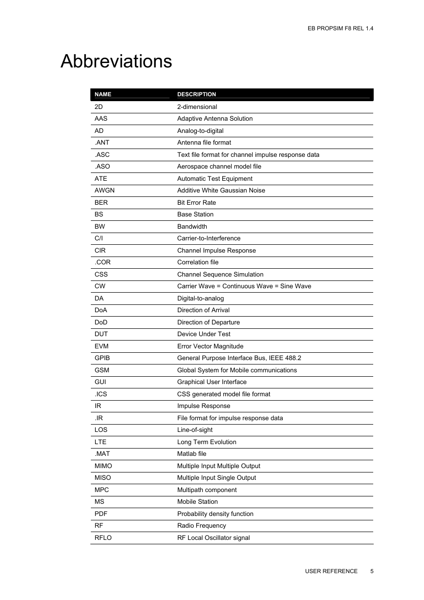
Abbreviations EB PROPSIM F8 REL 1.4 NAME 2D AAS AD .ANT .ASC .ASO ATE AWGN BER BS BW C/I CIR .COR CSS CW DA DoA DoD DUT EVM GPIB GSM GUI .ICS IR .IR LOS LTE .MAT MIMO MISO MPC MS PDF RF RFLO DESCRIPTION 2-dimensional Adaptive Antenna Solution Analog-to-digital Antenna file format Text file format for channel impulse response data Aerospace channel model file Automatic Test Equipment Additive White Gaussian Noise Bit Error Rate Base Station Bandwidth Carrier-to-Interference Channel Impulse Response Correlation file Channel Sequence Simulation Carrier Wave = Continuous Wave = Sine Wave Digital-to-analog Direction of Arrival Direction of Departure Device Under Test Error Vector Magnitude General Purpose Interface Bus, IEEE 488.2 Global System for Mobile communications Graphical User Interface CSS generated model file format Impulse Response File format for impulse response data Line-of-sight Long Term Evolution Matlab file Multiple Input Multiple Output Multiple Input Single Output Multipath component Mobile Station Probability density function Radio Frequency RF Local Oscillator signal USER REFERENCE 5
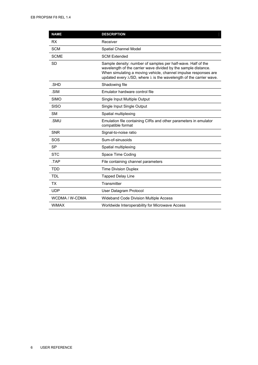
EB PROPSIM F8 REL 1.4 NAME RX SCM SCME SD .SHD .SIM SIMO SISO SM .SMU SNR SOS SP STC .TAP TDD TDL TX UDP WCDMA / W-CDMA WiMAX DESCRIPTION Receiver Spatial Channel Model SCM Extended Sample density: number of samples per half-wave. Half of the wavelength of the carrier wave divided by the sample distance. When simulating a moving vehicle, channel impulse responses are updated every /SD, where  is the wavelength of the carrier wave. Shadowing file Emulator hardware control file Single Input Multiple Output Single Input Single Output Spatial multiplexing Emulation file containing CIRs and other parameters in emulator compatible format Signal-to-noise ratio Sum-of-sinusoids Spatial multiplexing Space Time Coding File containing channel parameters Time Division Duplex Tapped Delay Line Transmitter User Datagram Protocol Wideband Code Division Multiple Access Worldwide Interoperability for Microwave Access 6 USER REFERENCE
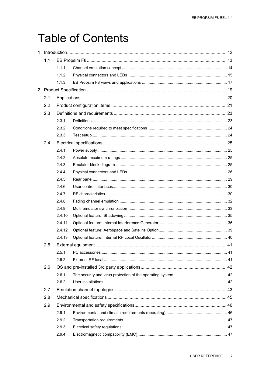
Table of Contents EB PROPSIM F8 REL 1.4 1.1.1 1.1.2 1.1.3 1 Introduction.................................................................................................................................. 12 1.1 EB Propsim F8.................................................................................................................. 13 Channel emulation concept .............................................................................................. 14 Physical connectors and LEDs......................................................................................... 15 EB Propsim F8 views and applications ............................................................................ 17 2 Product Specification .................................................................................................................. 19 2.1 Applications....................................................................................................................... 20 2.2 Product configuration items .............................................................................................. 21 2.3 Definitions and requirements ............................................................................................ 23 Definitions......................................................................................................................... 23 Conditions required to meet specifications ....................................................................... 24 Test setup......................................................................................................................... 24 2.4 Electrical specifications..................................................................................................... 25 Power supply.................................................................................................................... 25 2.4.1 Absolute maximum ratings ............................................................................................... 25 2.4.2 Emulator block diagram.................................................................................................... 25 2.4.3 Physical connectors and LEDs......................................................................................... 26 2.4.4 Rear panel........................................................................................................................ 29 2.4.5 User control interfaces...................................................................................................... 30 2.4.6 RF characteristics............................................................................................................. 30 2.4.7 2.4.8 Fading channel emulation ................................................................................................ 32 2.4.9 Multi-emulator synchronization......................................................................................... 33 2.4.10 Optional feature: Shadowing ............................................................................................ 35 2.4.11 Optional feature: Internal Interference Generator............................................................. 36 2.4.12 Optional feature: Aerospace and Satellite Option............................................................. 39 2.4.13 Optional feature: Internal RF Local Oscillator................................................................... 40 2.5 External equipment ........................................................................................................... 41 PC accessories ................................................................................................................ 41 External RF local .............................................................................................................. 41 2.6 OS and pre-installed 3rd party applications...................................................................... 42 The security and virus protection of the operating system................................................ 42 User installations .............................................................................................................. 42 2.7 Emulation channel topologies........................................................................................... 43 2.8 Mechanical specifications ................................................................................................. 45 2.9 Environmental and safety specifications........................................................................... 46 Environmental and climatic requirements (operating) ...................................................... 46 Transportation requirements ............................................................................................ 47 Electrical safety regulations.............................................................................................. 47 Electromagnetic compatibility (EMC)................................................................................ 47 2.9.1 2.9.2 2.9.3 2.9.4 2.3.1 2.3.2 2.3.3 2.5.1 2.5.2 2.6.1 2.6.2 USER REFERENCE 7
分享到:
收藏