ADCNC
Function Reference Manual
2.0
Wei-Li Chuang
MAPS-Embedded System Section
1
�
Revision sheet:
Rev Date
Author
Description
2.0
2014.10.14
Weili
Release ADCNC function reference manual
MAPS-Embedded System Section
2
�
1. Introduction
The ADCNC library is a hardware-independent library which is developed for the
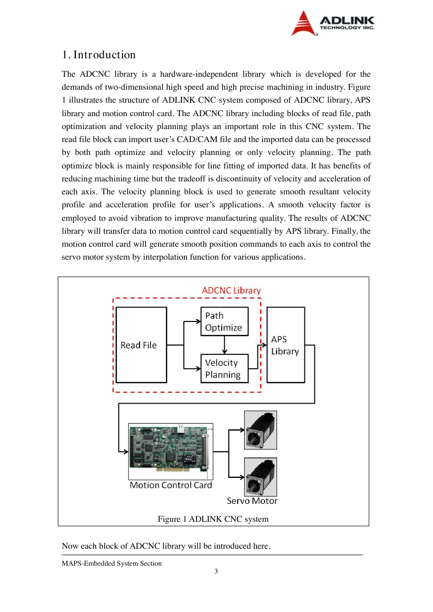
demands of two-dimensional high speed and high precise machining in industry. Figure
1 illustrates the structure of ADLINK CNC system composed of ADCNC library, APS
library and motion control card. The ADCNC library including blocks of read file, path
optimization and velocity planning plays an important role in this CNC system. The
read file block can import user’s CAD/CAM file and the imported data can be processed
by both path optimize and velocity planning or only velocity planning. The path
optimize block is mainly responsible for line fitting of imported data. It has benefits of
reducing machining time but the tradeoff is discontinuity of velocity and acceleration of
each axis. The velocity planning block is used to generate smooth resultant velocity
profile and acceleration profile for user’s applications. A smooth velocity factor is
employed to avoid vibration to improve manufacturing quality. The results of ADCNC
library will transfer data to motion control card sequentially by APS library. Finally, the
motion control card will generate smooth position commands to each axis to control the
servo motor system by interpolation function for various applications.
Figure 1 ADLINK CNC system
Now each block of ADCNC library will be introduced here.
MAPS-Embedded System Section
3
�
(1) Read file block:
An example below shows a basic format of user’s CAD/CAM file being able to
recognize by read file block should include items opt (option), x and y (absolute position
of axes or arc center) and theta (arc angle). The detailed bit define of opt will be
introduced in the description of structure POS_DATA_2D_F64. On the other hand, the
absolute position of each axis and arc angle can be floating values. The unit of arc angle
is degree and its resolution is 10E-6. For example, if desired angle of arc is 90.0 degree,
the input should be 90000000.0.
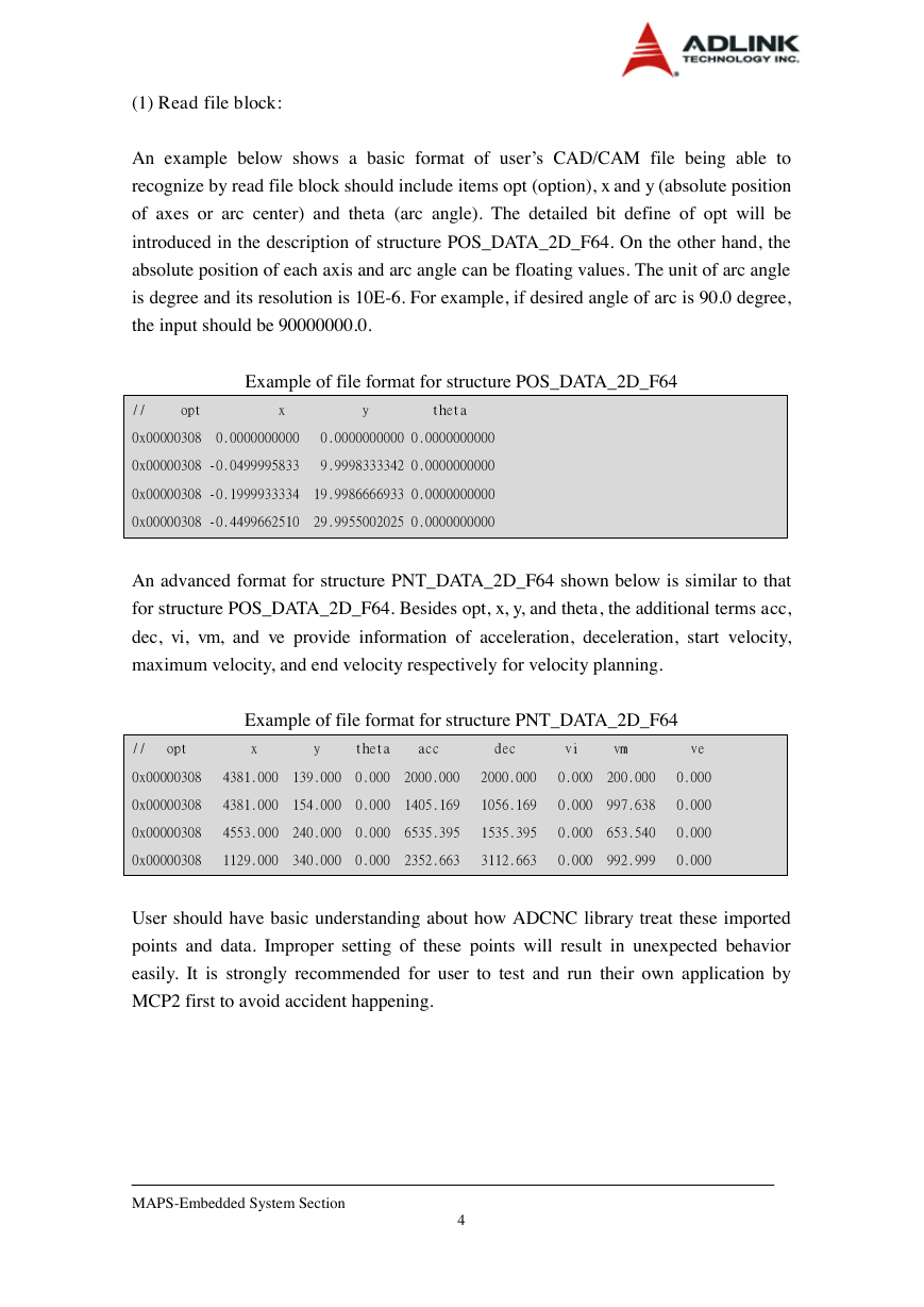
Example of file format for structure POS_DATA_2D_F64
// opt x y theta
0x00000308 0.0000000000 0.0000000000 0.0000000000
0x00000308 -0.0499995833 9.9998333342 0.0000000000
0x00000308 -0.1999933334 19.9986666933 0.0000000000
0x00000308 -0.4499662510 29.9955002025 0.0000000000
An advanced format for structure PNT_DATA_2D_F64 shown below is similar to that
for structure POS_DATA_2D_F64. Besides opt, x, y, and theta, the additional terms acc,
dec, vi, vm, and ve provide information of acceleration, deceleration, start velocity,
maximum velocity, and end velocity respectively for velocity planning.
Example of file format for structure PNT_DATA_2D_F64
// opt x y theta acc dec vi vm ve
0x00000308 4381.000 139.000 0.000 2000.000 2000.000 0.000 200.000 0.000
0x00000308 4381.000 154.000 0.000 1405.169 1056.169 0.000 997.638 0.000
0x00000308 4553.000 240.000 0.000 6535.395 1535.395 0.000 653.540 0.000
0x00000308 1129.000 340.000 0.000 2352.663 3112.663 0.000 992.999 0.000
User should have basic understanding about how ADCNC library treat these imported
points and data. Improper setting of these points will result in unexpected behavior
easily. It is strongly recommended for user to test and run their own application by
MCP2 first to avoid accident happening.
MAPS-Embedded System Section
4
�
(2) Path optimize block:
Only one input parameter tolerance error is needed for path optimization, and its unit is
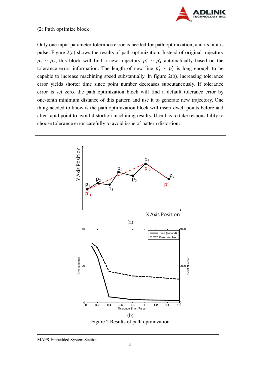
pulse. Figure 2(a) shows the results of path optimization: Instead of original trajectory
automatically based on the
~
~ , this block will find a new trajectory
~
is long enough to be
tolerance error information. The length of new line
capable to increase machining speed substantially. In figure 2(b), increasing tolerance
error yields shorter time since point number decreases subcutaneously. If tolerance
error is set zero, the path optimization block will find a default tolerance error by
one-tenth minimum distance of this pattern and use it to generate new trajectory. One
thing needed to know is the path optimization block will insert dwell points before and
after rapid point to avoid distortion machining results. User has to take responsibility to
choose tolerance error carefully to avoid issue of pattern distortion.
(a)
(b)
Figure 2 Results of path optimization
MAPS-Embedded System Section
5
00.20.40.60.811.21.41.602040Time (second)Tolerence Error (Pulse) 00.20.40.60.811.21.41.6020004000Point NumberTime (second)Point Number�
(3) Velocity planning block
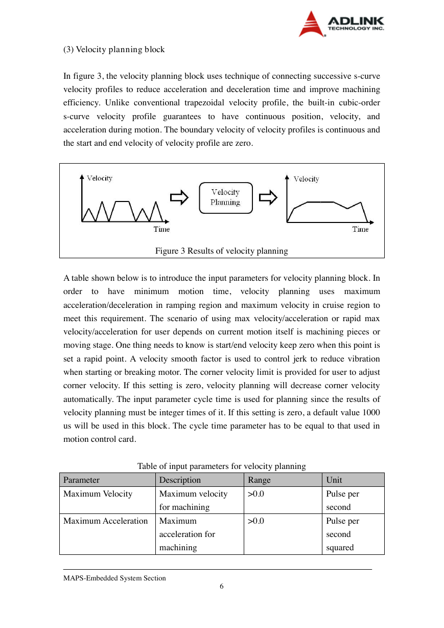
In figure 3, the velocity planning block uses technique of connecting successive s-curve
velocity profiles to reduce acceleration and deceleration time and improve machining
efficiency. Unlike conventional trapezoidal velocity profile, the built-in cubic-order
s-curve velocity profile guarantees to have continuous position, velocity, and
acceleration during motion. The boundary velocity of velocity profiles is continuous and
the start and end velocity of velocity profile are zero.
Figure 3 Results of velocity planning
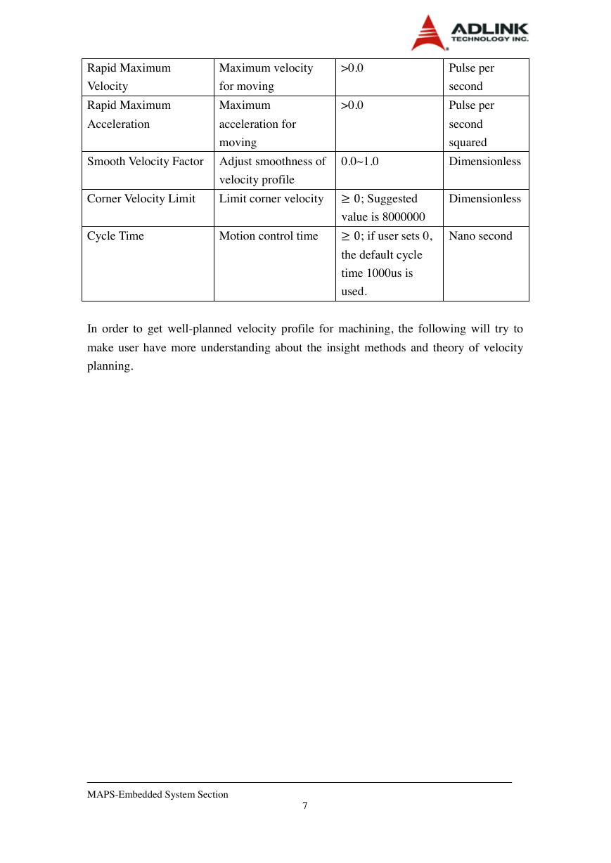
A table shown below is to introduce the input parameters for velocity planning block. In
order
to have minimum motion
time, velocity planning uses maximum
acceleration/deceleration in ramping region and maximum velocity in cruise region to
meet this requirement. The scenario of using max velocity/acceleration or rapid max
velocity/acceleration for user depends on current motion itself is machining pieces or
moving stage. One thing needs to know is start/end velocity keep zero when this point is
set a rapid point. A velocity smooth factor is used to control jerk to reduce vibration
when starting or breaking motor. The corner velocity limit is provided for user to adjust
corner velocity. If this setting is zero, velocity planning will decrease corner velocity
automatically. The input parameter cycle time is used for planning since the results of
velocity planning must be integer times of it. If this setting is zero, a default value 1000
us will be used in this block. The cycle time parameter has to be equal to that used in
motion control card.
Table of input parameters for velocity planning
Parameter
Description
Range
Maximum Velocity
Maximum velocity
>0.0
Maximum Acceleration Maximum
>0.0
for machining
acceleration for
machining
MAPS-Embedded System Section
6
Unit
Pulse per
second
Pulse per
second
squared
�
Rapid Maximum
Maximum velocity
>0.0
Velocity
Rapid Maximum
for moving
Maximum
Acceleration
acceleration for
>0.0
moving
Pulse per
second
Pulse per
second
squared
Smooth Velocity Factor Adjust smoothness of
0.0~1.0
Dimensionless
velocity profile
Corner Velocity Limit
Limit corner velocity ; Suggested
Dimensionless
Cycle Time
Motion control time
; if user sets 0,
Nano second
value is 8000000
the default cycle
time 1000us is
used.
In order to get well-planned velocity profile for machining, the following will try to
make user have more understanding about the insight methods and theory of velocity
planning.
MAPS-Embedded System Section
7
�
a. Corner velocity constraint
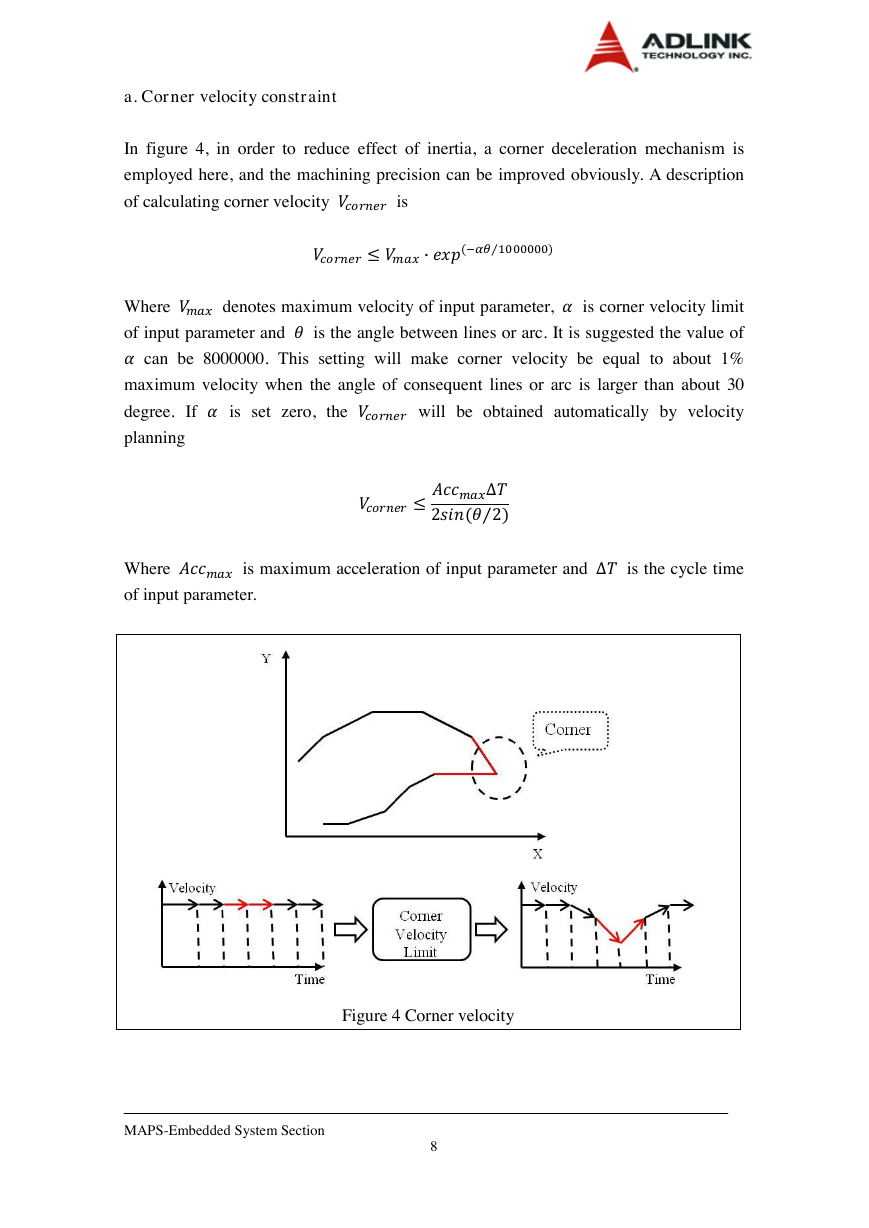
In figure 4, in order to reduce effect of inertia, a corner deceleration mechanism is
employed here, and the machining precision can be improved obviously. A description
of calculating corner velocity is
Where denotes maximum velocity of input parameter, is corner velocity limit
of input parameter and is the angle between lines or arc. It is suggested the value of
can be 8000000. This setting will make corner velocity be equal to about 1%
maximum velocity when the angle of consequent lines or arc is larger than about 30
degree. If is set zero, the will be obtained automatically by velocity
planning
Where is maximum acceleration of input parameter and is the cycle time
of input parameter.
Figure 4 Corner velocity
MAPS-Embedded System Section
8
�


 2023年江西萍乡中考道德与法治真题及答案.doc
 2012年重庆南川中考生物真题及答案.doc
 2013年江西师范大学地理学综合及文艺理论基础考研真题.doc
 2020年四川甘孜小升初语文真题及答案I卷.doc
 2020年注册岩土工程师专业基础考试真题及答案.doc
 2023-2024学年福建省厦门市九年级上学期数学月考试题及答案.doc
 2021-2022学年辽宁省沈阳市大东区九年级上学期语文期末试题及答案.doc
 2022-2023学年北京东城区初三第一学期物理期末试卷及答案.doc
 2018上半年江西教师资格初中地理学科知识与教学能力真题及答案.doc
 2012年河北国家公务员申论考试真题及答案-省级.doc
 2020-2021学年江苏省扬州市江都区邵樊片九年级上学期数学第一次质量检测试题及答案.doc
 2022下半年黑龙江教师资格证中学综合素质真题及答案.doc