Date: 2008.04.14
Scanning Laser Range Finder
UTM-30LX/LN
Specification
Europe’s Official
Distributor
1010 Cambourne Business Park, Cambridge, CB23 6DP UK.
Tel +44 (1223) 923 930 : Fax +44 (1223) 923 940
info@sentekeurope.com : www.sentekeurope.com
Symbol
Amendment Details
Amendment
Date
Amended by Number
Approved by Checked by Drawn by Designed by
MORI
KAMITANI
HINO
Title
Drawing
No.
UTM-30LX/LN
Specification
C 42 3615
1/5
�
1.
Introduction
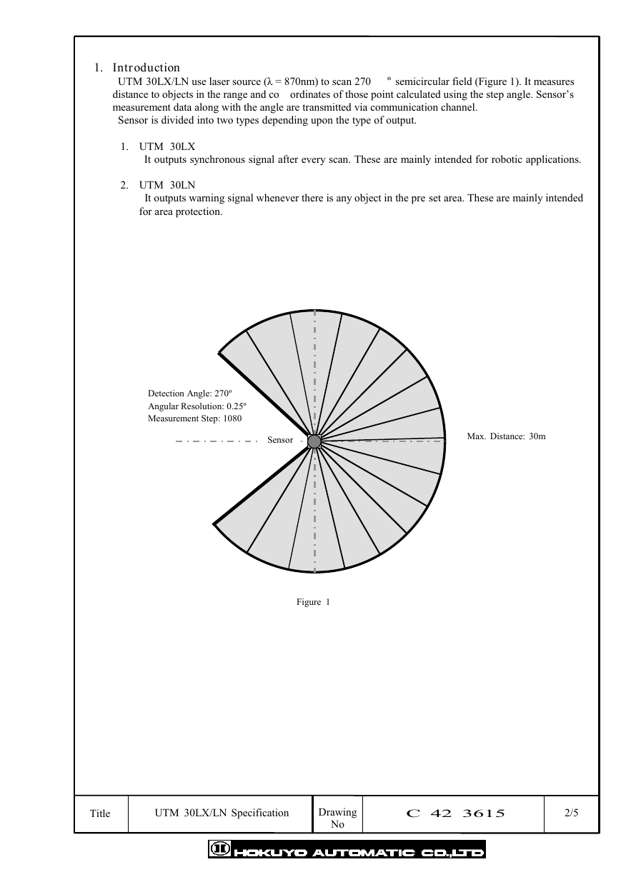
UTM 30LX/LN use laser source (λ = 870nm) to scan 270
º semicircular field (Figure 1). It measures
distance to objects in the range and co ordinates of those point calculated using the step angle. Sensor’s
measurement data along with the angle are transmitted via communication channel.
Sensor is divided into two types depending upon the type of output.
1. UTM 30LX
It outputs synchronous signal after every scan. These are mainly intended for robotic applications.
2. UTM 30LN
It outputs warning signal whenever there is any object in the pre set area. These are mainly intended
for area protection.
Detection Angle: 270º
Angular Resolution: 0.25º
Measurement Step: 1080
Sensor
Max. Distance: 30m
Figure 1
Title
UTM 30LX/LN Specification
Drawing
No
C 42 3615
2/5
�
2. Specifications
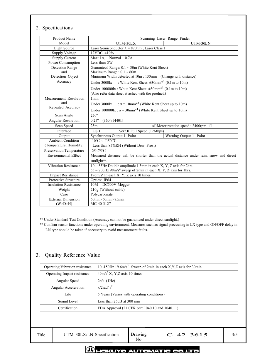
Product Name
Model
Light Source
Supply Voltage
Supply Current
Power Consumption
Detection Range
and
Detection Object
Accuracy
Measurement Resolution
and
Repeated Accuracy
Scan Angle
Angular Resolution
Scan Speed
Interface
Output
Ambient Condition
(Temperature, Humidity)
Preservation Temperature
Environmental Effect
Vibration Resistance
Impact Resistance
Protective Structure
Insulation Resistance
Weight
Case
External Dimension
(W×D×H)
UTM-30LX
UTM-30LN
Scanning Laser Range Finder
Laser Semiconductor λ = 870nm , Laser Class 1
12VDC ±10%
Max: 1A, Normal : 0.7A
Less than 8W
Guaranteed Range: 0.1 ~ 30m (White Kent Sheet)
Maximum Range : 0.1 ~ 60m
Minimum Width detected at 10m : 130mm (Change with distance)
Under 3000lx : White Kent Sheet: ±30mm*¹ (0.1m to 10m)
Under 100000lx : White Kent Sheet: ±50mm*¹ (0.1m to 10m)
(Also refer data sheet attached with the product.)
1mm
Under 3000lx : σ = 10mm*¹ (White Kent Sheet up to 10m)
Under 100000lx : σ = 30mm*¹ (White Kent Sheet up to 10m)
270º
0.25 º (360°/1440
25m
USB
Synchronous Output 1 Point
10 ºC ~ 50 ºC
Less than 85%RH (Without Dew, Frost)
25~75 ºC
Measured distance will be shorter than the actual distance under rain, snow and direct
sunlight*².
10 ~ 55Hz Double amplitude 1.5mm in each X, Y, Z axis for 2hrs.
55 ~ 200Hz 98m/s2 sweep of 2min in each X, Y, Z axis for 1hrs.
196m/s2 In each X, Y, Z axis 10 times.
Optics: IP64
10M
210g (Without cable)
Polycarbonate
60mm×60mm×85mm
MC 40 3127
sMotor rotation speed : 2400rpm
Ver2.0 Full Speed (12Mbps)
Warning Output 1 Point
DC500V Megger
*¹ Under Standard Test Condition (Accuracy can not be guaranteed under direct sunlight.)
*² Confirm sensor functions under operating environment. Measures such as signal processing in LX type and ON/OFF delay in
LN type should be taken if necessary to avoid measurement faults.
3. Quality Reference Value
Operating Vibration resistance
Operating Impact resistance
Angular Speed
Angular Acceleration
Life
Sound Level
Certification
10~150Hz 19.6m/s2 Sweep of 2min in each X,Y,Z axis for 30min
49m/s2 X, Y,Z axis 10 times
2π/s (1Hz)
π/2rad/ s2
5 Years (Varies with operating conditions)
Less than 25dB at 300 mm
FDA Approval (21 CFR part 1040.10 and 1040.11)
Title
UTM 30LX/LN Specification
Drawing
No
C 42 3615
3/5
�
4. Interface
(1) Robot Cable 10Pin
Color
Brown
Blue
Green
White
Function
+12v Power
0v Power
Synchronous Output/ Warning Output
COM Output (0V: Common to Power)
(2) USB Connector
TYPE A
Note :
SG for communication and GND are connected internally (Isolated with Input VIN).
Isolate the device form any connection that generate electric noise.
This sensor is compatible with SCIP2.0 protocol standard.
5. Control Signal
(1) Synchronous Output (UTM 30LX)
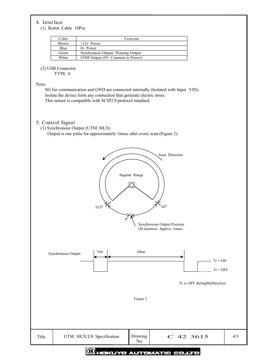
Output is one pulse for approximately 1msec after every scan (Figure 2).
Scan Direction
Angular Range
315º
45º
0º
Synchronous Output Position
On duration: Approx. 1msec.
Synchronous Output
1ms
24ms
Tr = ON
Tr = OFF
Tr is OFF duringMalfunction
Figure 2
Drawing
No
C 42 3615
4/5
Title
UTM 30LX/LN Specification
�
(2) Warning Signal (UTM 30LN)
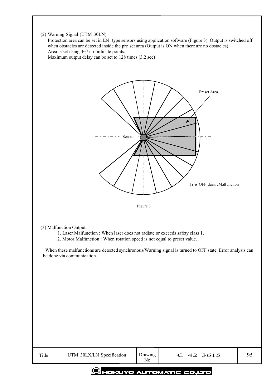
Protection area can be set in LN type sensors using application software (Figure 3). Output is switched off
when obstacles are detected inside the pre set area (Output is ON when there are no obstacles).
Area is set using 3~7 co ordinate points.
Maximum output delay can be set to 128 times (3.2 sec)
Preset Area
Tr is OFF duringMalfunction
Sensor
Figure 3
(3) Malfunction Output:
1. Laser Malfunction : When laser does not radiate or exceeds safety class 1.
2. Motor Malfunction : When rotation speed is not equal to preset value.
When these malfunctions are detected synchronous/Warning signal is turned to OFF state. Error analysis can
be done via communication.
Title
UTM 30LX/LN Specification
Drawing
No
C 42 3615
5/5
�


 2023年江西萍乡中考道德与法治真题及答案.doc
 2012年重庆南川中考生物真题及答案.doc
 2013年江西师范大学地理学综合及文艺理论基础考研真题.doc
 2020年四川甘孜小升初语文真题及答案I卷.doc
 2020年注册岩土工程师专业基础考试真题及答案.doc
 2023-2024学年福建省厦门市九年级上学期数学月考试题及答案.doc
 2021-2022学年辽宁省沈阳市大东区九年级上学期语文期末试题及答案.doc
 2022-2023学年北京东城区初三第一学期物理期末试卷及答案.doc
 2018上半年江西教师资格初中地理学科知识与教学能力真题及答案.doc
 2012年河北国家公务员申论考试真题及答案-省级.doc
 2020-2021学年江苏省扬州市江都区邵樊片九年级上学期数学第一次质量检测试题及答案.doc
 2022下半年黑龙江教师资格证中学综合素质真题及答案.doc