logo资料库

MT2523开发资料.pdf

第1页 / 共107页
第2页 / 共107页
第3页 / 共107页
第4页 / 共107页
第5页 / 共107页
第6页 / 共107页
第7页 / 共107页
第8页 / 共107页
资料共107页,剩余部分请下载后查看
1. System Overview
Platform Features
1.2. Multimedia Features
1.3. Bluetooth Features
1.4. MT2523G/D Platform Block Diagram
2. System Configuration
Strapping Resistors
2.2. Mode Selection
3. Pin Description
MT2523G Ball Diagram
3.1.1. MT2523G Pin Coordination
3.1.2. MT2523G Detailed Pin Description
3.2. MT2523D Ball Diagram
3.2.1. MT2523D Pin Coordination
3.2.2. MT2523D Detailed Pin Description
4. Electrical Characteristics
Absolute Maximum Ratings
4.2. Operating Conditions
4.2.1. General Operating Conditions
4.2.2. I/O Ports Characteristics
4.2.3. External Clock Source
4.2.3.1. Digitally Controlled Crystal Oscillator (DCXO)
4.2.3.2. 32kHz Crystal Oscillator (XOSC32)
4.2.4. ESD Electrical Sensitivity
4.3. Display Controller
4.3.1. MIPI DBI TYPE-C Interface
4.3.2. MIPI DSI Interface
4.4. MIPI DBI TYPE-C Interface Characteristics
4.4.1. Serial Data Write Mode
4.4.2. Serial Data Read Mode
4.5. MIPI DBI TYPE-C Interface Color Coding
4.5.1. 3-wire Serial Data Interface Write (A0+8-bit)
4.5.2. 3-wire Serial Data Interface Write (A0+9-bit)
4.5.3. 4-wire Serial Data Interface Write (8-bit)
4.5.4. 2-data-pin Mode Write (A0+8-bit)
4.5.5. 2-data-pin Mode Write (A0+9-bit)
4.5.6. 2-data pin Mode Write (A0+12-bit)
4.6. MIPI DSI Interface Characteristics
4.6.1. HS Clock Transmission
4.6.2. HS Data Transmission
4.6.3. Turnaround Procedure
4.7. MIPI DSI Interface Color Coding
4.8. Camera Interface
4.8.1. Multi Data Channels
4.8.2. Camera Interface Characteristics
5. Bluetooth RF Subsystem
Bluetooth RF Block Diagram
5.2. Functional Specifications
5.2.1. Basic Data Rate – Receiver Specifications
5.2.2. Basic Data Rate – Transmitter Specification
5.2.3. Enhanced Data Rate – Receiver Specifications
5.2.4. Enhanced Data Rate – Transmitter Specifications
5.2.5. Bluetooth LE – Receiver Specifications
5.2.6. Bluetooth LE – Transmitter Specifications
6. Power Management Unit
Introduction
6.2. Power Supply Schemes
6.3. Voltage Regular
6.3.1. LDO
6.3.1.1. LDO Types
6.3.1.2. LDO Functional Specifications
6.3.1.3. Regulator ON
6.3.1.4. Regulator Off
6.3.2. VCORE (Buck Mode)
6.3.2.1. VCORE Functional Specifications
6.4. Low Power Mode
6.5. Pulse Charger (PCHR)
6.5.1. Charger Detection
6.5.2. Charging Control
6.5.3. Pulse Charger Functional Specifications
6.6. Power On/Off Sequence
6.7. LED Current Sink (ISINK)
6.7.1. LED Current Sink Functional Specifications
6.8. Vibrator Driver
6.9. PMU AUXADC
7. Low Power Control System
Power Sources
7.2. MTCMOS Power Domains
7.3. Power modes
8. Package Information
MT2523G Package Mechanical Data
8.2. MT2523G Thermal Operating Specifications
8.3. MT2523D Package Mechanical Data
8.4. MT2523D Thermal Operating Specifications
8.5. MT2523G/D Lead-free Packaging
9. Ordering Information
MT2523G/D Top Marking Definition
10. Functional Overview
Host Processor Subsystem
10.1.1. ARM® Cortex®-M4 with FPU
10.1.2. Cache Controller
10.1.3. Memory Management
10.1.4. Memory Protection Unit (MPU)
10.1.5. Nested Vectored Interrupt Controller (NVIC)
10.1.6. External Interrupt Controller (EINT)
10.1.7. Bus Architecture
10.1.8. Direct Memory Access Controller (DMA)
10.2. Communication Interface
10.2.1. Universal Asynchronous Receiver Transmitter (UART)
10.2.2. Serial Peripheral Interface (SPI)
10.2.3. Inter-Integrated Circuit Interface (I2C)
10.2.4. Memory Stick and SD Memory Card Controller (MSDC)
10.2.5. USB2.0 High-Speed Device Controller
10.3. Peripherals
10.3.1. Pulse-Width Modulation (PWM)
10.3.2. General Purpose Inputs/Outputs (GPIO)
10.3.3. Keypad Scanner
10.3.4. General Purpose Timer (GPT)
10.3.5. OS Timer
10.3.6. Real Time Clock (RTC)
10.3.7. General Purpose Counter
10.3.8. True Random Number Generator (TRNG)
10.3.9. Accessory Detector (ACCDET)
10.4. Analog Baseband
10.4.1. General Purpose DAC (GPDAC)
10.4.1.1. Block Description
10.4.1.2. Functional Specifications
10.4.2. Auxiliary ADC
10.4.2.1. Block Description
10.4.2.2. Functional Specifications
10.4.3. Audio Mixed-Signal Blocks
10.4.3.1. Block Description
10.4.3.2. Functional Specifications
10.4.4. Phase Locked Loop (PLL) and Oscillators
10.4.4.1. Block Descriptions
10.4.4.2. Function Specifications
10.5. Audio Front End
loginid=hunk.ou@arrowasia.com,time=2016-09-01 03:09:37,ip=183.240.202.25,doctitle=MT2523_Datasheet.pdf,company=Arrow_IoT MT2523D/G Datasheet Version: Release date: 0.41 2016-04-28 © 2015 - 2016 MediaTek Inc. This document contains information that is proprietary to MediaTek Inc. (“MediaTek”) and/or its licensor(s). MediaTek cannot grant you permission for any material that is owned by third parties. You may only use or reproduce this document if you have agreed to and been bound by the applicable license agreement with MediaTek (“License Agreement”) and been granted explicit permission within the License Agreement (“Permitted User”). If you are not a Permitted User, please cease any access or use of this document immediately. Any unauthorized use, reproduction or disclosure of this document in whole or in part is strictly prohibited. THIS DOCUMENT IS PROVIDED ON AN “AS-IS” BASIS ONLY. MEDIATEK EXPRESSLY DISCLAIMS ANY AND ALL WARRANTIES OF ANY KIND AND SHALL IN NO EVENT BE LIABLE FOR ANY CLAIMS RELATING TO OR ARISING OUT OF THIS DOCUMENT OR ANY USE OR INABILITY TO USE THEREOF. Specifications contained herein are subject to change without notice.
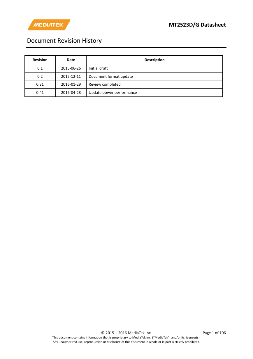
Document Revision History MT2523D/G Datasheet Revision Date Description 0.1 0.2 0.31 0.41 2015-06-26 2015-12-11 2016-01-29 2016-04-28 Initial draft Document format update Review completed Update power performance loginid=hunk.ou@arrowasia.com,time=2016-09-01 03:09:37,ip=183.240.202.25,doctitle=MT2523_Datasheet.pdf,company=Arrow_IoT This document contains information that is proprietary to MediaTek Inc. (“MediaTek”) and/or its licensor(s). Any unauthorized use, reproduction or disclosure of this document in whole or in part is strictly prohibited. © 2015 – 2016 MediaTek Inc. Page 1 of 106 Me dia Tek Con fide ntia l A Me dia Tek
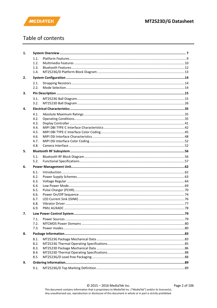
MT2523D/G Datasheet Table of contents System Overview ................................................................................................................................... 7 1.1. Platform Features ............................................................................................................................... 9 1.2. Multimedia Features ........................................................................................................................ 10 1.3. Bluetooth Features ........................................................................................................................... 12 1.4. MT2523G/D Platform Block Diagram ............................................................................................... 13 System Configuration ........................................................................................................................... 14 2.1. Strapping Resistors ........................................................................................................................... 14 2.2. Mode Selection ................................................................................................................................. 14 Pin Description ..................................................................................................................................... 15 3.1. MT2523G Ball Diagram ..................................................................................................................... 15 3.2. MT2523D Ball Diagram ..................................................................................................................... 26 Electrical Characteristics ....................................................................................................................... 35 4.1. Absolute Maximum Ratings .............................................................................................................. 35 4.2. Operating Conditions ........................................................................................................................ 35 4.3. Display Controller ............................................................................................................................. 41 4.4. MIPI DBI TYPE-C Interface Characteristics ........................................................................................ 42 4.5. MIPI DBI TYPE-C Interface Color Coding ........................................................................................... 45 4.6. MIPI DSI Interface Characteristics .................................................................................................... 48 4.7. MIPI DSI Interface Color Coding ....................................................................................................... 52 4.8. Camera Interface .............................................................................................................................. 52 Bluetooth RF Subsystem ....................................................................................................................... 56 5.1. Bluetooth RF Block Diagram ............................................................................................................. 56 5.2. Functional Specifications .................................................................................................................. 57 Power Management Unit...................................................................................................................... 62 6.1. Introduction ...................................................................................................................................... 62 6.2. Power Supply Schemes ..................................................................................................................... 63 6.3. Voltage Regular ................................................................................................................................ 64 6.4. Low Power Mode .............................................................................................................................. 69 6.5. Pulse Charger (PCHR) ........................................................................................................................ 70 6.6. Power On/Off Sequence ................................................................................................................... 74 6.7. LED Current Sink (ISINK) ................................................................................................................... 76 6.8. Vibrator Driver .................................................................................................................................. 77 6.9. PMU AUXADC ................................................................................................................................... 78 Low Power Control System ................................................................................................................... 79 7.1. Power Sources .................................................................................................................................. 79 7.2. MTCMOS Power Domains ................................................................................................................ 80 7.3. Power modes .................................................................................................................................... 80 Package Information ............................................................................................................................. 83 8.1. MT2523G Package Mechanical Data ................................................................................................ 83 8.2. MT2523G Thermal Operating Specifications .................................................................................... 85 8.3. MT2523D Package Mechanical Data ................................................................................................ 86 8.4. MT2523D Thermal Operating Specifications .................................................................................... 88 8.5. MT2523G/D Lead-free Packaging ..................................................................................................... 88 Ordering Information ............................................................................................................................ 89 9.1. MT2523G/D Top Marking Definition ................................................................................................ 89 This document contains information that is proprietary to MediaTek Inc. (“MediaTek”) and/or its licensor(s). Any unauthorized use, reproduction or disclosure of this document in whole or in part is strictly prohibited. © 2015 – 2016 MediaTek Inc. Page 2 of 106 1. 2. 3. 4. 5. 6. 7. 8. 9. loginid=hunk.ou@arrowasia.com,time=2016-09-01 03:09:37,ip=183.240.202.25,doctitle=MT2523_Datasheet.pdf,company=Arrow_IoT
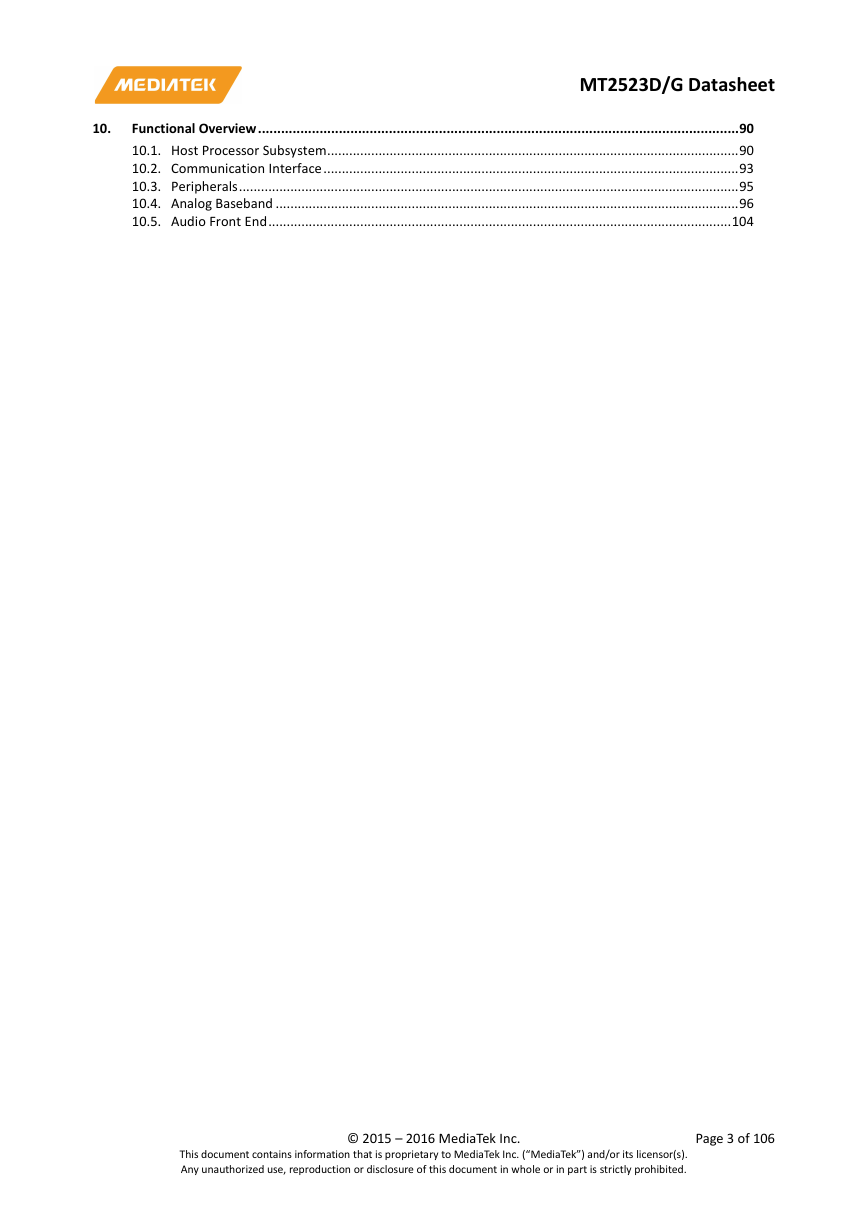
MT2523D/G Datasheet Functional Overview ............................................................................................................................. 90 10.1. Host Processor Subsystem ................................................................................................................ 90 10.2. Communication Interface ................................................................................................................. 93 10.3. Peripherals ........................................................................................................................................ 95 10.4. Analog Baseband .............................................................................................................................. 96 10.5. Audio Front End .............................................................................................................................. 104 10. loginid=hunk.ou@arrowasia.com,time=2016-09-01 03:09:37,ip=183.240.202.25,doctitle=MT2523_Datasheet.pdf,company=Arrow_IoT This document contains information that is proprietary to MediaTek Inc. (“MediaTek”) and/or its licensor(s). Any unauthorized use, reproduction or disclosure of this document in whole or in part is strictly prohibited. © 2015 – 2016 MediaTek Inc. Page 3 of 106
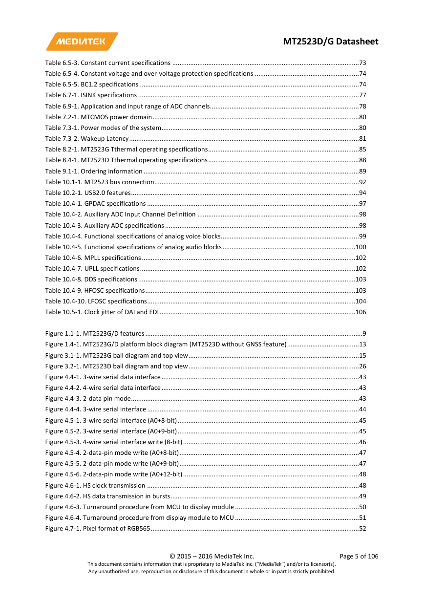
Lists of tables and figures MT2523D/G Datasheet Table 2.1-1. Strapping resistors table ................................................................................................................... 14 Table 2.2-1. Mode selection table ........................................................................................................................ 14 Table 3.1-1. MT2523G pin coordinates ................................................................................................................. 15 Table 3.1-2. Acronym for pin types ....................................................................................................................... 18 Table 3.1-3. MT2523G pin function description and power domain .................................................................... 18 Table 3.1-4. MT2523G GNSS part pin function description .................................................................................. 24 Table 3.2-1. MT2523D pin coordinates ................................................................................................................. 26 Table 3.2-2. Acronym for pin types ....................................................................................................................... 28 Table 3.2-3. MT2523D pin function description and power domain .................................................................... 29 Table 4.1-1. Absolute maximum ratings for power supply ................................................................................... 35 Table 4.1-2. Absolute maximum ratings for voltage input ................................................................................... 35 Table 4.1-3. Absolute maximum ratings for storage temperature ....................................................................... 35 Table 4.2-1. General operating conditions............................................................................................................ 35 Table 4.2-2. Recommended operating conditions for power supply.................................................................... 36 Table 4.2-3. Recommended operating conditions for voltage input .................................................................... 36 Table 4.2-4. Recommended operating conditions for operating temperature .................................................... 36 Table 4.2-5. Electrical characteristics .................................................................................................................... 36 Table 4.2-6. DCXO Characteristics (TA = 250C, VDD = 1.8V unless otherwise stated) (1) ..................................... 39 Table 4.2-7. Functional specifications of XOSC32 ................................................................................................. 39 Table 4.2-8. Recommended parameters for 32kHz crystal ................................................................................... 40 Table 4.2-9. ESD electrical characteristic of MT2523G ......................................................................................... 40 Table 4.2-10. ESD electrical characteristic of MT2523D ....................................................................................... 41 Table 4.4-1. Serial interface characteristics during write operation ..................................................................... 44 Table 4.4-2. Serial interface characteristics during read operation ...................................................................... 44 Table 4.6-1. HS clock transmission timing parameter........................................................................................... 48 Table 4.6-2. HS data transmission timing parameter ........................................................................................... 50 Table 4.6-3. Low power mode timing parameter ................................................................................................. 51 Table 4.8-1. I/O Port of MTK camera serial interface ........................................................................................... 53 Table 4.8-2. I/O port of MTK camera serial interface timing parameter .............................................................. 54 Table 5.2-1. Basic Data Rate – Receiver Specifications ......................................................................................... 57 Table 5.2-2. Basic Data Rate – Transmitter Specification ..................................................................................... 57 Table 5.2-3. Enhanced Data Rate –Receiver Specifications .................................................................................. 58 Table 5.2-4. Enhanced Data Rate – Transmitter Specifications ............................................................................ 59 Table 5.2-5. Bluetooth LE – Receiver Specifications ............................................................................................. 60 Table 5.2-6. Bluetooth LE – Transmitter Specification .......................................................................................... 60 Table 6.2-1. LDO Input power plan ....................................................................................................................... 63 Table 6.3-1. LDO types and brief specifications .................................................................................................... 65 Table 6.3-2. LDO specifications ............................................................................................................................. 66 Table 6.3-3. VCORE specifications ......................................................................................................................... 68 Table 6.5-1. Charger detection specifications ....................................................................................................... 73 Table 6.5-2. Pre-charge specifications .................................................................................................................. 73 loginid=hunk.ou@arrowasia.com,time=2016-09-01 03:09:37,ip=183.240.202.25,doctitle=MT2523_Datasheet.pdf,company=Arrow_IoT This document contains information that is proprietary to MediaTek Inc. (“MediaTek”) and/or its licensor(s). Any unauthorized use, reproduction or disclosure of this document in whole or in part is strictly prohibited. © 2015 – 2016 MediaTek Inc. Page 4 of 106
MT2523D/G Datasheet Table 6.5-3. Constant current specifications ........................................................................................................ 73 Table 6.5-4. Constant voltage and over-voltage protection specifications .......................................................... 74 Table 6.5-5. BC1.2 specifications .......................................................................................................................... 74 Table 6.7-1. ISINK specifications ........................................................................................................................... 77 Table 6.9-1. Application and input range of ADC channels ................................................................................... 78 Table 7.2-1. MTCMOS power domain ................................................................................................................... 80 Table 7.3-1. Power modes of the system .............................................................................................................. 80 Table 7.3-2. Wakeup Latency ................................................................................................................................ 81 Table 8.2-1. MT2523G Tthermal operating specifications .................................................................................... 85 Table 8.4-1. MT2523D Tthermal operating specifications .................................................................................... 88 Table 9.1-1. Ordering information ........................................................................................................................ 89 Table 10.1-1. MT2523 bus connection .................................................................................................................. 92 Table 10.2-1. USB2.0 features ............................................................................................................................... 94 Table 10.4-1. GPDAC specifications ...................................................................................................................... 97 Table 10.4-2. Auxiliary ADC Input Channel Definition .......................................................................................... 98 Table 10.4-3. Auxiliary ADC specifications ............................................................................................................ 98 Table 10.4-4. Functional specifications of analog voice blocks ............................................................................. 99 Table 10.4-5. Functional specifications of analog audio blocks .......................................................................... 100 Table 10.4-6. MPLL specifications ....................................................................................................................... 102 Table 10.4-7. UPLL specifications ........................................................................................................................ 102 Table 10.4-8. DDS specifications ......................................................................................................................... 103 Table 10.4-9. HFOSC specifications ..................................................................................................................... 103 Table 10.4-10. LFOSC specifications .................................................................................................................... 104 Table 10.5-1. Clock jitter of DAI and EDI ............................................................................................................. 106 Figure 1.1-1. MT2523G/D features ......................................................................................................................... 9 Figure 1.4-1. MT2523G/D platform block diagram (MT2523D without GNSS feature) ........................................ 13 Figure 3.1-1. MT2523G ball diagram and top view ............................................................................................... 15 Figure 3.2-1. MT2523D ball diagram and top view ............................................................................................... 26 Figure 4.4-1. 3-wire serial data interface .............................................................................................................. 43 Figure 4.4-2. 4-wire serial data interface .............................................................................................................. 43 Figure 4.4-3. 2-data pin mode ............................................................................................................................... 43 Figure 4.4-4. 3-wire serial interface ...................................................................................................................... 44 Figure 4.5-1. 3-wire serial interface (A0+8-bit) ..................................................................................................... 45 Figure 4.5-2. 3-wire serial interface (A0+9-bit) ..................................................................................................... 45 Figure 4.5-3. 4-wire serial interface write (8-bit) .................................................................................................. 46 Figure 4.5-4. 2-data-pin mode write (A0+8-bit) .................................................................................................... 47 Figure 4.5-5. 2-data-pin mode write (A0+9-bit) .................................................................................................... 47 Figure 4.5-6. 2-data-pin mode write (A0+12-bit) .................................................................................................. 48 Figure 4.6-1. HS clock transmission ...................................................................................................................... 48 Figure 4.6-2. HS data transmission in bursts ......................................................................................................... 49 Figure 4.6-3. Turnaround procedure from MCU to display module ..................................................................... 50 Figure 4.6-4. Turnaround procedure from display module to MCU ..................................................................... 51 Figure 4.7-1. Pixel format of RGB565 .................................................................................................................... 52 loginid=hunk.ou@arrowasia.com,time=2016-09-01 03:09:37,ip=183.240.202.25,doctitle=MT2523_Datasheet.pdf,company=Arrow_IoT This document contains information that is proprietary to MediaTek Inc. (“MediaTek”) and/or its licensor(s). Any unauthorized use, reproduction or disclosure of this document in whole or in part is strictly prohibited. © 2015 – 2016 MediaTek Inc. Page 5 of 106
MT2523D/G Datasheet Figure 4.7-2. Pixel format of loose RGB666 .......................................................................................................... 52 Figure 4.7-3. Pixel format of RGB565 .................................................................................................................... 52 Figure 4.8-1. Transmission order of multi data channels...................................................................................... 53 Figure 4.8-2. I/O port timing of SDR mode ........................................................................................................... 54 Figure 4.8-3. I/O port timing of DDR mode ........................................................................................................... 54 Figure 5.1-1. Bluetooth RF Transceiver System Diagram ...................................................................................... 56 Figure 6.1-1. MT2523G/D PMU block diagram ..................................................................................................... 62 Figure 6.3-1. MT2523G/D power domain ............................................................................................................ 64 Figure 6.3-2. LDO block diagram .......................................................................................................................... 65 Figure 6.5-1. PCHR block diagram ........................................................................................................................ 70 Figure 6.5-2. Charging states diagram ................................................................................................................. 71 Figure 6.6-1. Power-on/off control sequence by pressing PWRKEY .................................................................... 75 Figure 6.6-2. Power-on/off control sequence by charger plug in ........................................................................ 75 Figure 6.7-1. ISINK block diagram ........................................................................................................................ 77 Figure 7.1-1. Power sources provided by PMU for system power planning ......................................................... 79 Figure 8.1-1 Outlines and dimension of MT2523G TFBGA 9.2 mm * 6 mm, 246-ball, 0.4 mm pitch package ..... 85 Figure 8.3-1 Outlines and dimension of MT2523D TFBGA 6.2 mm * 5.8 mm, 165-ball, 0.4 mm pitch package .. 88 Figure 9.1-1. Mass production top marking of MT2523G ..................................................................................... 89 Figure 9.1-2. Mass production top marking of MT2523G ..................................................................................... 89 Figure 10.4-1. Block diagram of audio mixed-signal blocks .................................................................................. 99 Figure 10.4-2. Block diagram of PLL clock sources .............................................................................................. 102 Figure 10.5-1. Block diagram of digital circuits of audio front-end..................................................................... 104 Figure 10.5-2. Timing diagram of Bluetooth application .................................................................................... 105 Figure 10.5-3. Timing diagram of different clock rate Bluetooth application ..................................................... 105 Figure 10.5-4. EDI Format 1: EIAJ (FMT = 0) ........................................................................................................ 106 Figure 10.5-5. EDI Format 1: I2S (FMT = 1) ......................................................................................................... 106 loginid=hunk.ou@arrowasia.com,time=2016-09-01 03:09:37,ip=183.240.202.25,doctitle=MT2523_Datasheet.pdf,company=Arrow_IoT This document contains information that is proprietary to MediaTek Inc. (“MediaTek”) and/or its licensor(s). Any unauthorized use, reproduction or disclosure of this document in whole or in part is strictly prohibited. © 2015 – 2016 MediaTek Inc. Page 6 of 106
MT2523D/G Datasheet 1. System Overview MT2523G/D is a monolithic chip integrating leading edge power management unit, analog baseband and radio circuitry based on the low-power CMOS process. MT2523G/D is a feature-rich and extremely powerful single-chip solution for BT/BLE capability, and it is also ANT hardware ready. Based on the Coretex-M4 processor, MT2523G/D’s superb processing power, along with high bandwidth architecture and dedicated hardware support, provides a platform for high-performance wearable application and leading-edge sensor control applications. MT2523G/D is optimized for wearable products with the following strengths: • Ultra small package size • Ultra low power consumption for active and idle mode • Dynamic voltage scaling for optimized computing power • Built-in sensor hub and optimized sensor data capture engine Platform MT2523G/D is capable of running Coretex-M4 RISC processor, which provides the best trade-off between system performance and power consumption. MT2523G/D also provides a co-processor to offload the control for Bluetooth or GNSS. Coretex-M4 can easily use API to enable Bluetooth or GNSS function and make Coretex-M4 focus on your applications. For large amount of data transfers, high-performance DMA (direct memory access) with hardware flow control is implemented, which greatly enhances the data movement speed while reducing the MCU processing load. A special sensor DMA is also equipped to support sensor data capture with ultra low power consumption. Targeted as a media-rich platform for wearable applications, MT2523G/D also provides hardware security digital rights management for copyright protection. To further safeguard and protect the manufacturer’s investment in development, hardware flash content protection is provided to prevent unauthorized porting of the software load. Special versions with GNSS embedded are also available for GNSS related wearable applications. Memory MT2523G/D is embedded with MTK-patented low power PSRAM to improve active and idle current. MT2523G/D supports serial flash with various operating frequencies and flash sizes. Multimedia The MT2523G/D multimedia subsystem provides MediaTek proprietary serial interface for cameras. The camera resolution is up to VGA size. MT2523G/D also provides MediaTek proprietary serial interface and MIPI interface for LCM. The LCM resolution is up to 360x360. The software-based codec can be used to process various video types. To take advantage of the high MCU performance, GIF and PNG decoders are implemented by the software. loginid=hunk.ou@arrowasia.com,time=2016-09-01 03:09:37,ip=183.240.202.25,doctitle=MT2523_Datasheet.pdf,company=Arrow_IoT This document contains information that is proprietary to MediaTek Inc. (“MediaTek”) and/or its licensor(s). Any unauthorized use, reproduction or disclosure of this document in whole or in part is strictly prohibited. © 2015 – 2016 MediaTek Inc. Page 7 of 106
分享到:
收藏