RTL8231
S
MI Interface and Serial Interface control LED Display Controller
Rev. 0.5
19 Nov. 2009
Track ID:
Realtek Semiconductor Corp.
No. 2, Innovation Road II, Hsinchu Science Park, Hsinchu 300, Taiwan
Tel.: +886-3-578-0211 Fax: +886-3-577-6047
www.realtek.com
REALTEK CONFIDENTIAL for MTN �
RTL8231
Datasheet Draft
COPYRIGHT
©2008 Realtek Semiconductor Corp. All rights reserved. No part of this document may be reproduced,
transmitted, transcribed, stored in a retrieval system, or translated into any language in any form or by any
means without the written permission of Realtek Semiconductor Corp.
DISCLAIMER
Realtek provides this document “as is”, without warranty of any kind, neither expressed nor implied,
including, but not limited to, the particular purpose. Realtek may make improvements and/or changes in
this document or in the product described in this document at any time. This document could include
technical inaccuracies or typographical errors.
TRADEMARKS
Realtek is a trademark of Realtek Semiconductor Corporation. Other names mentioned in this document
are trademarks/registered trademarks of their respective owners.
USING THIS DOCUMENT
This document is intended for the hardware engineer’s general information on the Realtek RTL8389M
chips.
Though every effort has been made to ensure that this document is current and accurate, more information
may have become available subsequent to the production of this guide.
REVISION HISTORY
Revision
0.3
Release Date
2009/09/28
Summary
First release.
Serial Data Interface LED Display Controller
ii
Track ID: JATR-1076-21 Rev. 0.5
REALTEK CONFIDENTIAL for MTN �
RTL8231
Datasheet Draft
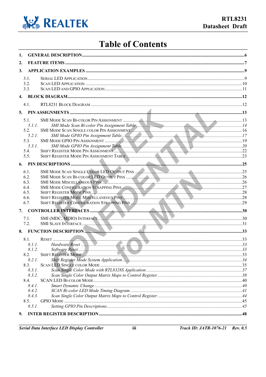
Table of Contents
3.1.
3.2.
3.3.
4.1.
5.1.1.
5.2.1.
5.3.1.
5.1.
5.2.
5.3.
5.4.
5.5.
1. GENERAL DESCRIPTION................................................................................................................................................6
2. FEATURE ITEMS ...............................................................................................................................................................7
3. APPLICATION EXAMPLES .............................................................................................................................................9
SERIAL LED APPLICATION...........................................................................................................................................9
SCAN LED APPLICATION ...........................................................................................................................................10
SCAN LED AND GPIO APPLICATION..........................................................................................................................11
4. BLOCK DIAGRAM...........................................................................................................................................................12
RTL8231 BLOCK DIAGRAM ......................................................................................................................................12
5. PIN ASSIGNMENTS .........................................................................................................................................................13
SMI MODE SCAN BI-COLOR PIN ASSIGNMENT ..........................................................................................................13
SMI Mode Scan Bi-color Pin Assignment Table ..............................................................................................14
SMI MODE SCAN SINGLE COLOR PIN ASSIGNMENT...................................................................................................16
SMI Mode GPIO Pin Assignment Table...........................................................................................................17
SMI MODE GPIO PIN ASSIGNMENT ..........................................................................................................................19
SMI Mode GPIO Pin Assignment Table...........................................................................................................20
SHIFT REGISTER MODE PIN ASSIGNMENT..................................................................................................................22
SHIFT REGISTER MODE PIN ASSIGNMENT TABLE.......................................................................................................23
6. PIN DESCRIPTIONS ........................................................................................................................................................25
SMI MODE SCAN SINGLE COLOR LED OUTPUT PINS ...............................................................................................25
SMI MODE SCAN BI-COLOR LED OUTPUT PINS .......................................................................................................26
SMI MODE MISCELLANEOUS PINS ............................................................................................................................26
SMI MODE CONFIGURATION STRAPPING PINS...........................................................................................................27
SHIFT REGISTER MODE PINS......................................................................................................................................28
SHIFT REGISTER MODE MISCELLANEOUS PINS..........................................................................................................28
SHIFT REGISTER CONFIGURATION STRAPPING PINS ...................................................................................................29
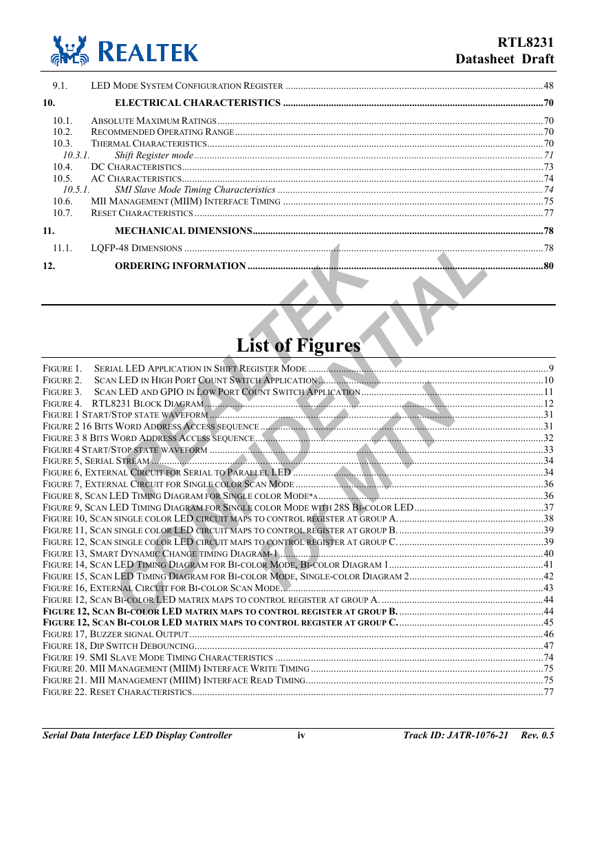
7. CONTROLLER INTERFACES .......................................................................................................................................30
SMI (MDC, MDIO) INTERFACE................................................................................................................................30
SMI SLAVE INTERFACE..............................................................................................................................................31
8. FUNCTION DESCRIPTION............................................................................................................................................33
RESET ........................................................................................................................................................................33
8.1.1.
Hardware Reset ...............................................................................................................................................33
8.1.2.
Software Reset..................................................................................................................................................33
SHIFT REGISTER MODE..............................................................................................................................................33
8.2.1.
Shift Register Mode System Application ..........................................................................................................34
SCAN LED SINGLE COLOR MODE..............................................................................................................................35
8.3.1.
Scan Single Color Mode with RTL8328S Application .....................................................................................37
8.3.2.
Scan Single Color Output Matrix Maps to Control Register ...........................................................................38
SCAN LED BI-COLOR MODE....................................................................................................................................40
8.4.1.
Smart Dynamic Change...................................................................................................................................40
8.4.2.
SCAN Bi-color LED Mode Timing Diagram ...................................................................................................41
8.4.3.
Scan Single Color Output Matrix Maps to Control Register ...........................................................................44
GPIO MODE ..............................................................................................................................................................45
8.5.1.
Setting GPIO Pin Descriptions........................................................................................................................45
INTER REGISTER DESCRIPTION ...............................................................................................................................48
6.1.
6.2.
6.3.
6.4.
6.5.
6.6.
6.7.
8.1.
8.2.
8.3.
8.4.
7.1.
7.2.
8.5.
9.
Serial Data Interface LED Display Controller
iii
Track ID: JATR-1076-21 Rev. 0.5
REALTEK CONFIDENTIAL for MTN �
RTL8231
Datasheet Draft
LED MODE SYSTEM CONFIGURATION REGISTER ......................................................................................................48
ELECTRICAL CHARACTERISTICS .......................................................................................................70
ABSOLUTE MAXIMUM RATINGS.................................................................................................................................70
10.1.
RECOMMENDED OPERATING RANGE..........................................................................................................................70
10.2.
THERMAL CHARACTERISTICS.....................................................................................................................................70
10.3.
Shift Register mode..........................................................................................................................................71
DC CHARACTERISTICS...............................................................................................................................................73
10.4.
AC CHARACTERISTICS...............................................................................................................................................74
10.5.
SMI Slave Mode Timing Characteristics .........................................................................................................74
10.6. MII MANAGEMENT (MIIM) INTERFACE TIMING .......................................................................................................75
RESET CHARACTERISTICS ..........................................................................................................................................77
10.7.
MECHANICAL DIMENSIONS...................................................................................................................78
LQFP-48 DIMENSIONS ..............................................................................................................................................78
ORDERING INFORMATION .....................................................................................................................80
10.3.1.
10.5.1.
11.1.
9.1.
10.
11.
12.
List of Figures
FIGURE 1. SERIAL LED APPLICATION IN SHIFT REGISTER MODE ...............................................................................................9
FIGURE 2. SCAN LED IN HIGH PORT COUNT SWITCH APPLICATION.........................................................................................10
FIGURE 3. SCAN LED AND GPIO IN LOW PORT COUNT SWITCH APPLICATION........................................................................11
FIGURE 4. RTL8231 BLOCK DIAGRAM......................................................................................................................................12
FIGURE 1 START/STOP STATE WAVEFORM ....................................................................................................................................31
FIGURE 2 16 BITS WORD ADDRESS ACCESS SEQUENCE................................................................................................................31
FIGURE 3 8 BITS WORD ADDRESS ACCESS SEQUENCE..................................................................................................................32
FIGURE 4 START/STOP STATE WAVEFORM ....................................................................................................................................33
FIGURE 5, SERIAL STREAM ...........................................................................................................................................................34
FIGURE 6, EXTERNAL CIRCUIT FOR SERIAL TO PARALLEL LED ...................................................................................................34
FIGURE 7, EXTERNAL CIRCUIT FOR SINGLE COLOR SCAN MODE ..................................................................................................36
FIGURE 8, SCAN LED TIMING DIAGRAM FOR SINGLE COLOR MODE*A.........................................................................................36
FIGURE 9, SCAN LED TIMING DIAGRAM FOR SINGLE COLOR MODE WITH 28S BI-COLOR LED...................................................37
FIGURE 10, SCAN SINGLE COLOR LED CIRCUIT MAPS TO CONTROL REGISTER AT GROUP A..........................................................38
FIGURE 11, SCAN SINGLE COLOR LED CIRCUIT MAPS TO CONTROL REGISTER AT GROUP B..........................................................39
FIGURE 12, SCAN SINGLE COLOR LED CIRCUIT MAPS TO CONTROL REGISTER AT GROUP C..........................................................39
FIGURE 13, SMART DYNAMIC CHANGE TIMING DIAGRAM-1 ........................................................................................................40
FIGURE 14, SCAN LED TIMING DIAGRAM FOR BI-COLOR MODE, BI-COLOR DIAGRAM 1.............................................................41
FIGURE 15, SCAN LED TIMING DIAGRAM FOR BI-COLOR MODE, SINGLE-COLOR DIAGRAM 2.....................................................42
FIGURE 16, EXTERNAL CIRCUIT FOR BI-COLOR SCAN MODE........................................................................................................43
FIGURE 12, SCAN BI-COLOR LED MATRIX MAPS TO CONTROL REGISTER AT GROUP A. ................................................................44
FIGURE 12, SCAN BI-COLOR LED MATRIX MAPS TO CONTROL REGISTER AT GROUP B. .........................................................44
FIGURE 12, SCAN BI-COLOR LED MATRIX MAPS TO CONTROL REGISTER AT GROUP C..........................................................45
FIGURE 17, BUZZER SIGNAL OUTPUT............................................................................................................................................46
FIGURE 18, DIP SWITCH DEBOUNCING..........................................................................................................................................47
FIGURE 19. SMI SLAVE MODE TIMING CHARACTERISTICS ..........................................................................................................74
FIGURE 20. MII MANAGEMENT (MIIM) INTERFACE WRITE TIMING ............................................................................................75
FIGURE 21. MII MANAGEMENT (MIIM) INTERFACE READ TIMING..............................................................................................75
FIGURE 22. RESET CHARACTERISTICS...........................................................................................................................................77
Serial Data Interface LED Display Controller
iv
Track ID: JATR-1076-21 Rev. 0.5
REALTEK CONFIDENTIAL for MTN �
RTL8231
Datasheet Draft
Serial Data Interface LED Display Controller
v
Track ID: JATR-1076-21 Rev. 0.5
REALTEK CONFIDENTIAL for MTN �
RTL8231
Datasheet Draft
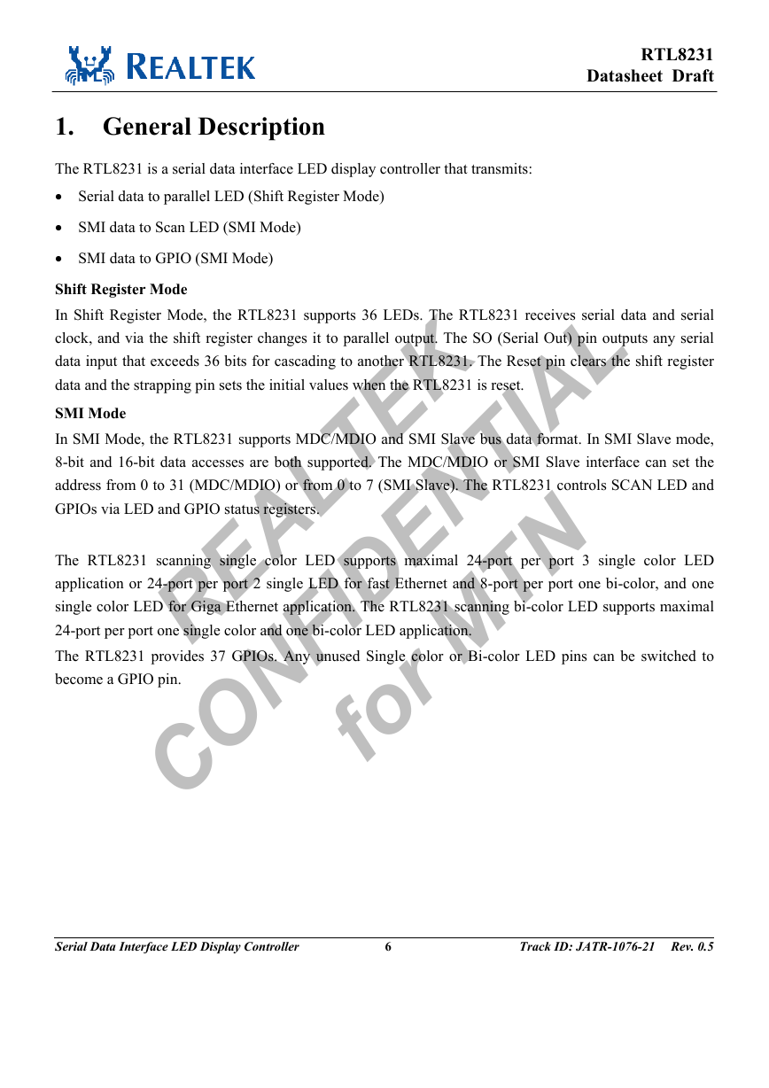
1. General Description
The RTL8231 is a serial data interface LED display controller that transmits:
• Serial data to parallel LED (Shift Register Mode)
• SMI data to Scan LED (SMI Mode)
• SMI data to GPIO (SMI Mode)
Shift Register Mode
In Shift Register Mode, the RTL8231 supports 36 LEDs. The RTL8231 receives serial data and serial
clock, and via the shift register changes it to parallel output. The SO (Serial Out) pin outputs any serial
data input that exceeds 36 bits for cascading to another RTL8231. The Reset pin clears the shift register
data and the strapping pin sets the initial values when the RTL8231 is reset.
SMI Mode
In SMI Mode, the RTL8231 supports MDC/MDIO and SMI Slave bus data format. In SMI Slave mode,
8-bit and 16-bit data accesses are both supported. The MDC/MDIO or SMI Slave interface can set the
address from 0 to 31 (MDC/MDIO) or from 0 to 7 (SMI Slave). The RTL8231 controls SCAN LED and
GPIOs via LED and GPIO status registers.
The RTL8231 scanning single color LED supports maximal 24-port per port 3 single color LED
application or 24-port per port 2 single LED for fast Ethernet and 8-port per port one bi-color, and one
single color LED for Giga Ethernet application. The RTL8231 scanning bi-color LED supports maximal
24-port per port one single color and one bi-color LED application.
The RTL8231 provides 37 GPIOs. Any unused Single color or Bi-color LED pins can be switched to
become a GPIO pin.
Serial Data Interface LED Display Controller
6
Track ID: JATR-1076-21 Rev. 0.5
REALTEK CONFIDENTIAL for MTN �
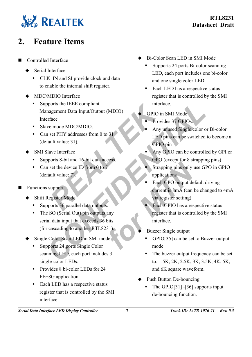
2. Feature Items
Controlled Interface
Serial Interface
CLK_IN and SI provide clock and data
to enable the internal shift register.
MDC/MDIO Interface
Supports the IEEE compliant
Management Data Input/Output (MDIO)
Interface
Slave mode MDC/MDIO.
Can set PHY addresses from 0 to 31
(default value: 31).
SMI Slave Interface
Supports 8-bit and 16-bit data access.
Can set the device ID from 0 to 7
(default value: 7).
Functions support
Shift Register Mode
Supports 36 parallel data outputs.
The SO (Serial Out) pin outputs any
serial data input that exceeds 36 bits
(for cascading to another RTL8231).
Single Color Scan LED in SMI mode
Supports 24 ports Single Color
scanning LED, each port includes 3
single-color LEDs.
Provides 8 bi-color LEDs for 24
FE+8G application
Each LED has a respective status
register that is controlled by the SMI
interface.
RTL8231
Datasheet Draft
Bi-Color Scan LED in SMI Mode
Supports 24 ports Bi-color scanning
LED, each port includes one bi-color
and one single color LED.
Each LED has a respective status
register that is controlled by the SMI
interface.
GPIO in SMI Mode
Provides 37 GPIOs.
Any unused Single color or Bi-color
LED pins can be switched to become a
GPIO pin
Any GPIO can be controlled by GPI or
GPO (except for 8 strapping pins)
Strapping pins only use GPO in GPIO
applications
Each GPO output default driving
current is 8mA (can be changed to 4mA
via register setting)
Each GPIO has a respective status
register that is controlled by the SMI
interface.
Buzzer Single output
GPIO[35] can be set to Buzzer output
mode.
The buzzer output frequency can be set
to: 1.5K, 2K, 2.5K, 3K, 3.5K, 4K, 5K,
and 6K square waveform.
Push Button De-bouncing
The GPIO[31]~[36] supports input
de-bouncing function.
Serial Data Interface LED Display Controller
7
Track ID: JATR-1076-21 Rev. 0.5
REALTEK CONFIDENTIAL for MTN �
RTL8231
Datasheet Draft
LED Blinking Speed Change
Each LED blinking speed can be
changed via LED status registers.
Each LED status register has 3-bits that
control LED speed (32ms to 1024ms).
Chip Package
LQFP-48 package
The GPI pin can be latched only if the
same input signal continues for 100ms.
LED Output Synchronization
All LEDs (Single color mode 72+8
LEDs, Bi-color mode 48 LEDs) can
change synchronization status via
register commands
GPIO Output Synchronization
All 37 GPIOs output synchronization
status can be changed via register
commands.
Serial Data Interface LED Display Controller
8
Track ID: JATR-1076-21 Rev. 0.5
REALTEK CONFIDENTIAL for MTN �





 2023年江西萍乡中考道德与法治真题及答案.doc
 2012年重庆南川中考生物真题及答案.doc
 2013年江西师范大学地理学综合及文艺理论基础考研真题.doc
 2020年四川甘孜小升初语文真题及答案I卷.doc
 2020年注册岩土工程师专业基础考试真题及答案.doc
 2023-2024学年福建省厦门市九年级上学期数学月考试题及答案.doc
 2021-2022学年辽宁省沈阳市大东区九年级上学期语文期末试题及答案.doc
 2022-2023学年北京东城区初三第一学期物理期末试卷及答案.doc
 2018上半年江西教师资格初中地理学科知识与教学能力真题及答案.doc
 2012年河北国家公务员申论考试真题及答案-省级.doc
 2020-2021学年江苏省扬州市江都区邵樊片九年级上学期数学第一次质量检测试题及答案.doc
 2022下半年黑龙江教师资格证中学综合素质真题及答案.doc