logo资料库

dsp28335寄存器手册.pdf

第1页 / 共141页
第2页 / 共141页
第3页 / 共141页
第4页 / 共141页
第5页 / 共141页
第6页 / 共141页
第7页 / 共141页
第8页 / 共141页
资料共141页,剩余部分请下载后查看
TMS320x2833x, 2823x System Control and Interrupts
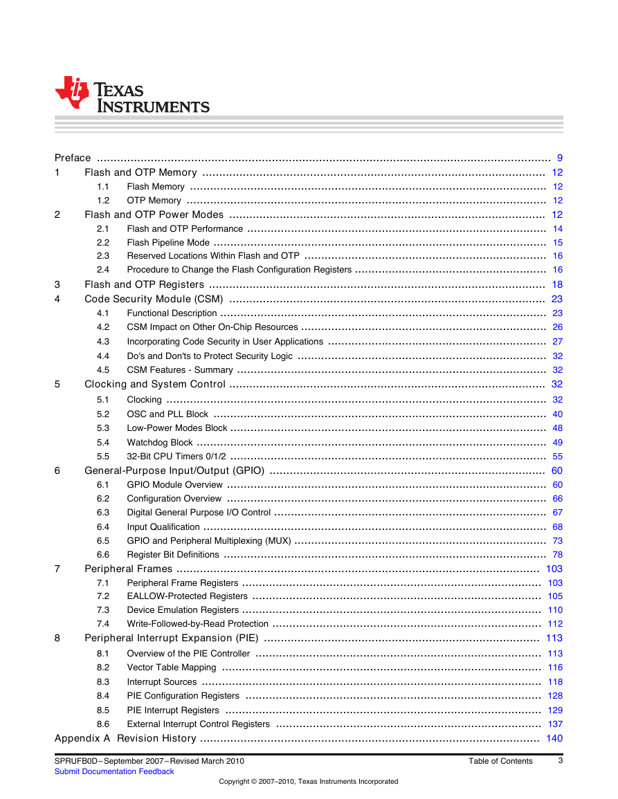
Table of Contents
Preface
1 Flash and OTP Memory
1.1 Flash Memory
1.2 OTP Memory
2 Flash and OTP Power Modes
2.1 Flash and OTP Performance
2.2 Flash Pipeline Mode
2.3 Reserved Locations Within Flash and OTP
2.4 Procedure to Change the Flash Configuration Registers
3 Flash and OTP Registers
4 Code Security Module (CSM)
4.1 Functional Description
4.2 CSM Impact on Other On-Chip Resources
4.3 Incorporating Code Security in User Applications
4.3.1 Environments That Require Security Unlocking
4.3.2 Password Match Flow
4.3.3 Unsecuring Considerations for Devices With/Without Code Security
4.3.3.1 C Code Example to Unsecure
4.3.3.2 C Code Example to Resecure
4.4 Do's and Don'ts to Protect Security Logic
4.4.1 Do's
4.4.2 Don'ts
4.5 CSM Features - Summary
5 Clocking and System Control
5.1 Clocking
5.1.1 Enabling/Disabling Clocks to the Peripheral Modules
5.2 OSC and PLL Block
5.2.1 PLL-Based Clock Module
5.2.2 Main Oscillator Fail Detection
5.2.3 XCLKOUT Generation
5.2.4 PLL Control (PLLCR) Register
5.2.5 PLL Control, Status and XCLKOUT Register Descriptions
5.2.6 External Reference Oscillator Clock Option
5.3 Low-Power Modes Block
5.4 Watchdog Block
5.4.1 Servicing The Watchdog Timer
5.4.2 Watchdog Reset or Watchdog Interrupt Mode
5.4.3 Watchdog Operation in Low Power Modes
5.4.4 Emulation Considerations
5.4.5 Watchdog Registers
5.5 32-Bit CPU Timers 0/1/2
6 General-Purpose Input/Output (GPIO)
6.1 GPIO Module Overview
6.2 Configuration Overview
6.3 Digital General Purpose I/O Control
6.4 Input Qualification
6.4.1 No Synchronization (asynchronous input)
6.4.2 Synchronization to SYSCLKOUT Only
6.4.3 Qualification Using a Sampling Window
6.5 GPIO and Peripheral Multiplexing (MUX)
6.6 Register Bit Definitions
7 Peripheral Frames
7.1 Peripheral Frame Registers
7.2 EALLOW-Protected Registers
7.3 Device Emulation Registers
7.4 Write-Followed-by-Read Protection
8 Peripheral Interrupt Expansion (PIE)
8.1 Overview of the PIE Controller
8.1.1 Interrupt Operation Sequence
8.2 Vector Table Mapping
8.3 Interrupt Sources
8.3.1 Procedure for Handling Multiplexed Interrupts
8.3.2 Procedures for Enabling And Disabling Multiplexed Peripheral Interrupts
8.3.3 Flow of a Multiplexed Interrupt Request From a Peripheral to the CPU
8.3.4 The PIE Vector Table
8.4 PIE Configuration Registers
8.5 PIE Interrupt Registers
8.5.1 PIE Interrupt Flag Registers
8.5.2 PIE Interrupt Enable Registers
8.5.3 CPU Interrupt Flag Register (IFR)
8.5.4 Interrupt Enable Register (IER) and Debug Interrupt Enable Register (DBGIER)
8.6 External Interrupt Control Registers
Appendix A Revision History
TMS320x2833x, 2823x System Control and Interrupts Reference Guide Literature Number: SPRUFB0D September 2007–Revised March 2010
2 Copyright © 2007–2010, Texas Instruments Incorporated SPRUFB0D– September 2007–Revised March 2010 Submit Documentation Feedback
2 3 4 5 6 4.1 4.2 4.3 4.4 4.5 5.1 5.2 5.3 5.4 5.5 1.1 1.2 2.1 2.2 2.3 2.4 Preface ....................................................................................................................................... 9 Flash and OTP Memory ...................................................................................................... 12 1 Flash Memory .......................................................................................................... 12 OTP Memory ........................................................................................................... 12 Flash and OTP Power Modes .............................................................................................. 12 Flash and OTP Performance ......................................................................................... 14 Flash Pipeline Mode ................................................................................................... 15 Reserved Locations Within Flash and OTP ........................................................................ 16 Procedure to Change the Flash Configuration Registers ......................................................... 16 Flash and OTP Registers .................................................................................................... 18 Code Security Module (CSM) .............................................................................................. 23 Functional Description ................................................................................................. 23 CSM Impact on Other On-Chip Resources ......................................................................... 26 Incorporating Code Security in User Applications ................................................................. 27 Do's and Don'ts to Protect Security Logic .......................................................................... 32 CSM Features - Summary ............................................................................................ 32 Clocking and System Control .............................................................................................. 32 Clocking ................................................................................................................. 32 OSC and PLL Block ................................................................................................... 40 Low-Power Modes Block .............................................................................................. 48 Watchdog Block ........................................................................................................ 49 32-Bit CPU Timers 0/1/2 .............................................................................................. 55 General-Purpose Input/Output (GPIO) .................................................................................. 60 GPIO Module Overview ............................................................................................... 60 Configuration Overview ............................................................................................... 66 Digital General Purpose I/O Control ................................................................................. 67 Input Qualification ...................................................................................................... 68 GPIO and Peripheral Multiplexing (MUX) ........................................................................... 73 Register Bit Definitions ................................................................................................ 78 Peripheral Frames ............................................................................................................ 103 Peripheral Frame Registers ......................................................................................... 103 EALLOW-Protected Registers ...................................................................................... 105 Device Emulation Registers ......................................................................................... 110 Write-Followed-by-Read Protection ................................................................................ 112 Peripheral Interrupt Expansion (PIE) .................................................................................. 113 Overview of the PIE Controller ..................................................................................... 113 Vector Table Mapping ............................................................................................... 116 Interrupt Sources ..................................................................................................... 118 PIE Configuration Registers ........................................................................................ 128 PIE Interrupt Registers .............................................................................................. 129 External Interrupt Control Registers ............................................................................... 137 Appendix A Revision History ..................................................................................................... 140 8.1 8.2 8.3 8.4 8.5 8.6 6.1 6.2 6.3 6.4 6.5 6.6 7.1 7.2 7.3 7.4 7 8 SPRUFB0D– September 2007–Revised March 2010 Submit Documentation Feedback Copyright © 2007–2010, Texas Instruments Incorporated Table of Contents 3
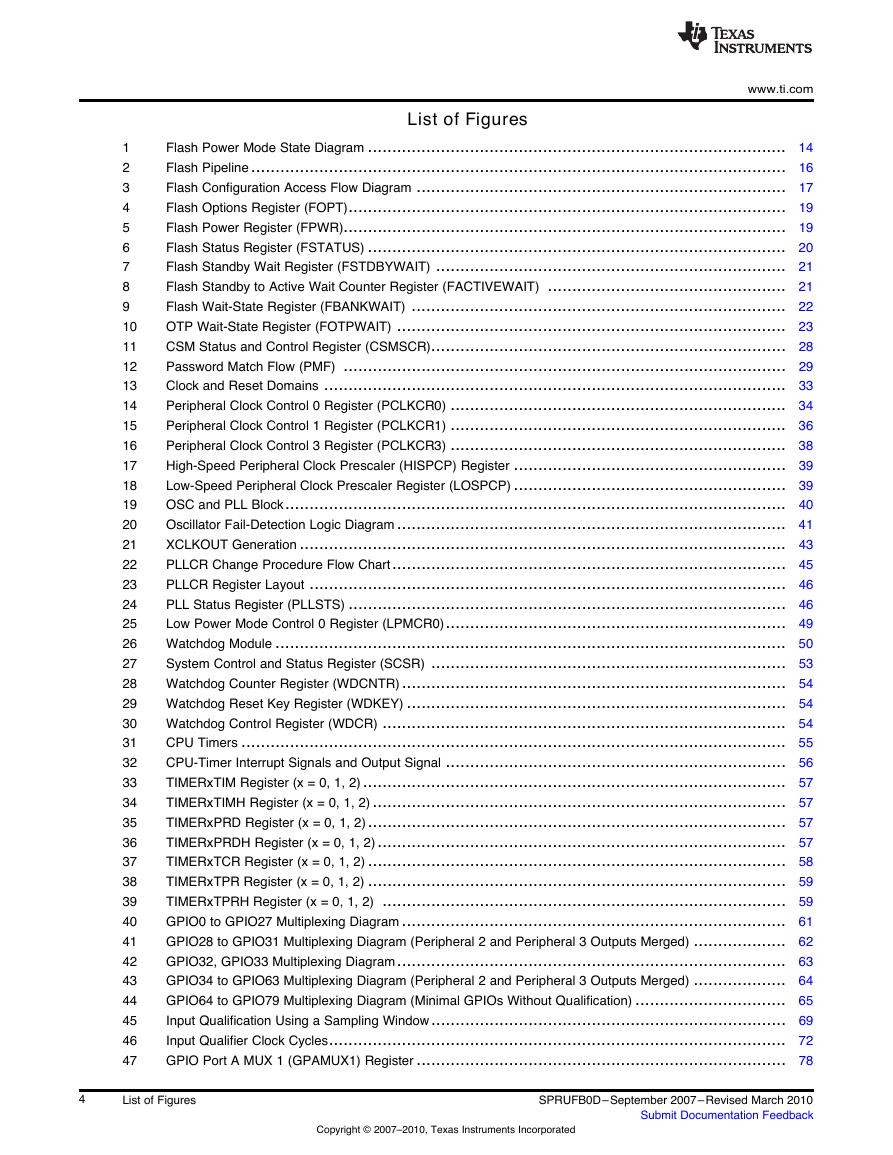
List of Figures www.ti.com Flash Power Mode State Diagram ...................................................................................... 14 Flash Pipeline .............................................................................................................. 16 Flash Configuration Access Flow Diagram ............................................................................ 17 Flash Options Register (FOPT).......................................................................................... 19 Flash Power Register (FPWR)........................................................................................... 19 Flash Status Register (FSTATUS) ...................................................................................... 20 Flash Standby Wait Register (FSTDBYWAIT) ........................................................................ 21 Flash Standby to Active Wait Counter Register (FACTIVEWAIT) ................................................. 21 Flash Wait-State Register (FBANKWAIT) ............................................................................. 22 OTP Wait-State Register (FOTPWAIT) ................................................................................ 23 CSM Status and Control Register (CSMSCR)......................................................................... 28 Password Match Flow (PMF) ........................................................................................... 29 Clock and Reset Domains ............................................................................................... 33 Peripheral Clock Control 0 Register (PCLKCR0) ..................................................................... 34 Peripheral Clock Control 1 Register (PCLKCR1) ..................................................................... 36 Peripheral Clock Control 3 Register (PCLKCR3) ..................................................................... 38 High-Speed Peripheral Clock Prescaler (HISPCP) Register ........................................................ 39 Low-Speed Peripheral Clock Prescaler Register (LOSPCP) ........................................................ 39 OSC and PLL Block....................................................................................................... 40 Oscillator Fail-Detection Logic Diagram ................................................................................ 41 XCLKOUT Generation .................................................................................................... 43 PLLCR Change Procedure Flow Chart................................................................................. 45 PLLCR Register Layout .................................................................................................. 46 PLL Status Register (PLLSTS) .......................................................................................... 46 Low Power Mode Control 0 Register (LPMCR0)...................................................................... 49 Watchdog Module ......................................................................................................... 50 System Control and Status Register (SCSR) ......................................................................... 53 Watchdog Counter Register (WDCNTR) ............................................................................... 54 Watchdog Reset Key Register (WDKEY) .............................................................................. 54 Watchdog Control Register (WDCR) ................................................................................... 54 CPU Timers ................................................................................................................ 55 CPU-Timer Interrupt Signals and Output Signal ...................................................................... 56 TIMERxTIM Register (x = 0, 1, 2) ....................................................................................... 57 TIMERxTIMH Register (x = 0, 1, 2) ..................................................................................... 57 TIMERxPRD Register (x = 0, 1, 2)...................................................................................... 57 TIMERxPRDH Register (x = 0, 1, 2) .................................................................................... 57 TIMERxTCR Register (x = 0, 1, 2) ...................................................................................... 58 TIMERxTPR Register (x = 0, 1, 2) ...................................................................................... 59 TIMERxTPRH Register (x = 0, 1, 2) ................................................................................... 59 GPIO0 to GPIO27 Multiplexing Diagram ............................................................................... 61 GPIO28 to GPIO31 Multiplexing Diagram (Peripheral 2 and Peripheral 3 Outputs Merged) ................... 62 GPIO32, GPIO33 Multiplexing Diagram................................................................................ 63 GPIO34 to GPIO63 Multiplexing Diagram (Peripheral 2 and Peripheral 3 Outputs Merged) ................... 64 GPIO64 to GPIO79 Multiplexing Diagram (Minimal GPIOs Without Qualification) ............................... 65 Input Qualification Using a Sampling Window......................................................................... 69 Input Qualifier Clock Cycles.............................................................................................. 72 GPIO Port A MUX 1 (GPAMUX1) Register ............................................................................ 78 1 2 3 4 5 6 7 8 9 10 11 12 13 14 15 16 17 18 19 20 21 22 23 24 25 26 27 28 29 30 31 32 33 34 35 36 37 38 39 40 41 42 43 44 45 46 47 4 List of Figures Copyright © 2007–2010, Texas Instruments Incorporated SPRUFB0D– September 2007–Revised March 2010 Submit Documentation Feedback
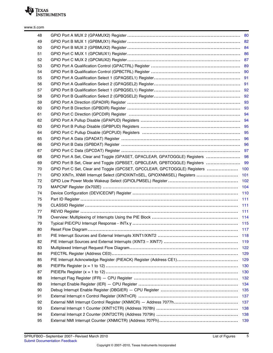
www.ti.com 48 49 50 51 52 53 54 55 56 57 58 59 60 61 62 63 64 65 66 67 68 69 70 71 72 73 74 75 76 77 78 79 80 81 82 83 84 85 86 87 88 89 90 91 92 93 94 95 GPIO Port A MUX 2 (GPAMUX2) Register ............................................................................ 80 GPIO Port B MUX 1 (GPBMUX1) Register ............................................................................ 82 GPIO Port B MUX 2 (GPBMUX2) Register ............................................................................ 84 GPIO Port C MUX 1 (GPCMUX1) Register............................................................................ 86 GPIO Port C MUX 2 (GPCMUX2) Register............................................................................ 87 GPIO Port A Qualification Control (GPACTRL) Register ............................................................ 89 GPIO Port B Qualification Control (GPBCTRL) Register ............................................................ 90 GPIO Port A Qualification Select 1 (GPAQSEL1) Register.......................................................... 91 GPIO Port A Qualification Select 2 (GPAQSEL2) Register.......................................................... 91 GPIO Port B Qualification Select 1 (GPBQSEL1) Register.......................................................... 92 GPIO Port B Qualification Select 2 (GPBQSEL2) Register.......................................................... 92 GPIO Port A Direction (GPADIR) Register ............................................................................ 93 GPIO Port B Direction (GPBDIR) Register ............................................................................ 93 GPIO Port C Direction (GPCDIR) Register ........................................................................... 94 GPIO Port A Pullup Disable (GPAPUD) Registers ................................................................... 94 GPIO Port B Pullup Disable (GPBPUD) Registers ................................................................... 95 GPIO Port C Pullup Disable (GPCPUD) Registers .................................................................. 95 GPIO Port A Data (GPADAT) Register ................................................................................ 96 GPIO Port B Data (GPBDAT) Register ................................................................................ 96 GPIO Port C Data (GPCDAT) Register ................................................................................ 97 GPIO Port A Set, Clear and Toggle (GPASET, GPACLEAR, GPATOGGLE) Registers ....................... 98 GPIO Port B Set, Clear and Toggle (GPBSET, GPBCLEAR, GPBTOGGLE) Registers ....................... 99 GPIO Port C Set, Clear and Toggle (GPCSET, GPCCLEAR, GPCTOGGLE) Registers ..................... 100 GPIO XINTn, XNMI Interrupt Select (GPIOXINTnSEL, GPIOXNMISEL) Registers ............................ 101 GPIO Low Power Mode Wakeup Select (GPIOLPMSEL) Register ............................................... 102 MAPCNF Register (0x702E) ........................................................................................... 104 Device Configuration (DEVICECNF) Register ....................................................................... 110 Part ID Register .......................................................................................................... 111 CLASSID Register ....................................................................................................... 111 REVID Register .......................................................................................................... 111 Overview: Multiplexing of Interrupts Using the PIE Block .......................................................... 114 Typical PIE/CPU Interrupt Response - INTx.y ....................................................................... 115 Reset Flow Diagram..................................................................................................... 117 PIE Interrupt Sources and External Interrupts XINT1/XINT2 ...................................................... 118 PIE Interrupt Sources and External Interrupts (XINT3 – XINT7) .................................................. 119 Multiplexed Interrupt Request Flow Diagram......................................................................... 122 PIECTRL Register (Address CE0)..................................................................................... 129 PIE Interrupt Acknowledge Register (PIEACK) Register (Address CE1)......................................... 129 PIEIFRx Register (x = 1 to 12) ......................................................................................... 130 PIEIERx Register (x = 1 to 12)......................................................................................... 130 Interrupt Flag Register (IFR) — CPU Register ...................................................................... 132 Interrupt Enable Register (IER) — CPU Register ................................................................... 134 Debug Interrupt Enable Register (DBGIER) — CPU Register .................................................... 135 External Interrupt n Control Register (XINTnCR) ................................................................... 137 External NMI Interrupt Control Register (XNMICR) — Address 7077h........................................... 137 External Interrupt 1 Counter (XINT1CTR) (Address 7078h) ....................................................... 138 External Interrupt 2 Counter (XINT2CTR) (Address 7079h) ....................................................... 138 External NMI Interrupt Counter (XNMICTR) (Address 707Fh)..................................................... 139 SPRUFB0D– September 2007–Revised March 2010 Submit Documentation Feedback Copyright © 2007–2010, Texas Instruments Incorporated List of Figures 5
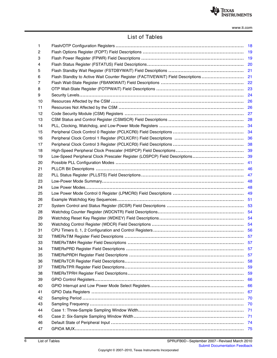
List of Tables www.ti.com Flash/OTP Configuration Registers ..................................................................................... 18 Flash Options Register (FOPT) Field Descriptions ................................................................... 19 Flash Power Register (FPWR) Field Descriptions .................................................................... 19 Flash Status Register (FSTATUS) Field Descriptions................................................................ 20 Flash Standby Wait Register (FSTDBYWAIT) Field Descriptions .................................................. 21 Flash Standby to Active Wait Counter Register (FACTIVEWAIT) Field Descriptions ............................ 21 Flash Wait-State Register (FBANKWAIT) Field Descriptions ....................................................... 22 OTP Wait-State Register (FOTPWAIT) Field Descriptions .......................................................... 23 Security Levels............................................................................................................. 24 Resources Affected by the CSM ........................................................................................ 26 Resources Not Affected by the CSM ................................................................................... 26 Code Security Module (CSM) Registers ............................................................................... 27 CSM Status and Control Register (CSMSCR) Field Descriptions .................................................. 28 PLL, Clocking, Watchdog, and Low-Power Mode Registers ........................................................ 34 Peripheral Clock Control 0 Register (PCLKCR0) Field Descriptions ............................................... 34 Peripheral Clock Control 1 Register (PCLKCR1) Field Descriptions .............................................. 36 Peripheral Clock Control 3 Register (PCLKCR3) Field Descriptions ............................................... 38 High-Speed Peripheral Clock Prescaler (HISPCP) Field Descriptions............................................. 39 Low-Speed Peripheral Clock Prescaler Register (LOSPCP) Field Descriptions.................................. 39 Possible PLL Configuration Modes ..................................................................................... 41 PLLCR Bit Descriptions .................................................................................................. 46 PLL Status Register (PLLSTS) Field Descriptions.................................................................... 47 Low-Power Mode Summary.............................................................................................. 48 Low Power Modes......................................................................................................... 48 Low Power Mode Control 0 Register (LPMCR0) Field Descriptions ............................................... 49 Example Watchdog Key Sequences.................................................................................... 51 System Control and Status Register (SCSR) Field Descriptions ................................................... 53 Watchdog Counter Register (WDCNTR) Field Descriptions......................................................... 54 Watchdog Reset Key Register (WDKEY) Field Descriptions........................................................ 54 Watchdog Control Register (WDCR) Field Descriptions ............................................................. 54 CPU Timers 0, 1, 2 Configuration and Control Registers............................................................ 56 TIMERxTIM Register Field Descriptions ............................................................................... 57 TIMERxTIMH Register Field Descriptions ............................................................................. 57 TIMERxPRD Register Field Descriptions .............................................................................. 57 TIMERxPRDH Register Field Descriptions ............................................................................ 57 TIMERxTCR Register Field Descriptions............................................................................... 58 TIMERxTPR Register Field Descriptions............................................................................... 59 TIMERxTPRH Register Field Descriptions............................................................................. 59 GPIO Control Registers................................................................................................... 66 GPIO Interrupt and Low Power Mode Select Registers.............................................................. 66 GPIO Data Registers ..................................................................................................... 67 Sampling Period ........................................................................................................... 70 Sampling Frequency ...................................................................................................... 70 Case 1: Three-Sample Sampling Window Width...................................................................... 71 Case 2: Six-Sample Sampling Window Width......................................................................... 71 Default State of Peripheral Input ........................................................................................ 74 GPIOA MUX................................................................................................................ 75 1 2 3 4 5 6 7 8 9 10 11 12 13 14 15 16 17 18 19 20 21 22 23 24 25 26 27 28 29 30 31 32 33 34 35 36 37 38 39 40 41 42 43 44 45 46 47 6 List of Tables Copyright © 2007–2010, Texas Instruments Incorporated SPRUFB0D– September 2007–Revised March 2010 Submit Documentation Feedback
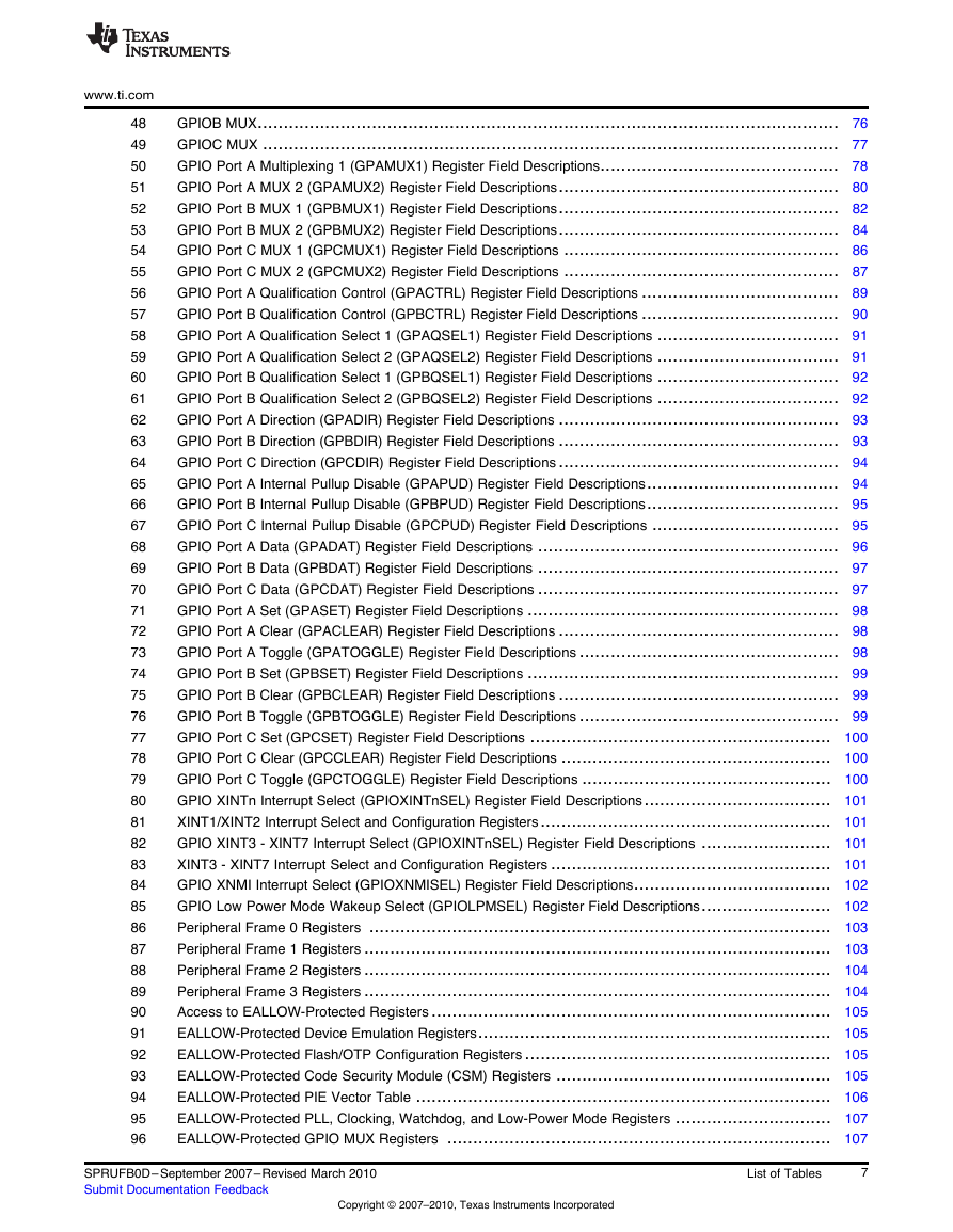
www.ti.com 48 49 50 51 52 53 54 55 56 57 58 59 60 61 62 63 64 65 66 67 68 69 70 71 72 73 74 75 76 77 78 79 80 81 82 83 84 85 86 87 88 89 90 91 92 93 94 95 96 GPIOB MUX................................................................................................................ 76 GPIOC MUX ............................................................................................................... 77 GPIO Port A Multiplexing 1 (GPAMUX1) Register Field Descriptions.............................................. 78 GPIO Port A MUX 2 (GPAMUX2) Register Field Descriptions...................................................... 80 GPIO Port B MUX 1 (GPBMUX1) Register Field Descriptions...................................................... 82 GPIO Port B MUX 2 (GPBMUX2) Register Field Descriptions...................................................... 84 GPIO Port C MUX 1 (GPCMUX1) Register Field Descriptions ..................................................... 86 GPIO Port C MUX 2 (GPCMUX2) Register Field Descriptions ..................................................... 87 GPIO Port A Qualification Control (GPACTRL) Register Field Descriptions ...................................... 89 GPIO Port B Qualification Control (GPBCTRL) Register Field Descriptions ...................................... 90 GPIO Port A Qualification Select 1 (GPAQSEL1) Register Field Descriptions ................................... 91 GPIO Port A Qualification Select 2 (GPAQSEL2) Register Field Descriptions ................................... 91 GPIO Port B Qualification Select 1 (GPBQSEL1) Register Field Descriptions ................................... 92 GPIO Port B Qualification Select 2 (GPBQSEL2) Register Field Descriptions ................................... 92 GPIO Port A Direction (GPADIR) Register Field Descriptions ...................................................... 93 GPIO Port B Direction (GPBDIR) Register Field Descriptions ...................................................... 93 GPIO Port C Direction (GPCDIR) Register Field Descriptions ...................................................... 94 GPIO Port A Internal Pullup Disable (GPAPUD) Register Field Descriptions..................................... 94 GPIO Port B Internal Pullup Disable (GPBPUD) Register Field Descriptions..................................... 95 GPIO Port C Internal Pullup Disable (GPCPUD) Register Field Descriptions .................................... 95 GPIO Port A Data (GPADAT) Register Field Descriptions .......................................................... 96 GPIO Port B Data (GPBDAT) Register Field Descriptions .......................................................... 97 GPIO Port C Data (GPCDAT) Register Field Descriptions .......................................................... 97 GPIO Port A Set (GPASET) Register Field Descriptions ............................................................ 98 GPIO Port A Clear (GPACLEAR) Register Field Descriptions ...................................................... 98 GPIO Port A Toggle (GPATOGGLE) Register Field Descriptions .................................................. 98 GPIO Port B Set (GPBSET) Register Field Descriptions ............................................................ 99 GPIO Port B Clear (GPBCLEAR) Register Field Descriptions ...................................................... 99 GPIO Port B Toggle (GPBTOGGLE) Register Field Descriptions .................................................. 99 GPIO Port C Set (GPCSET) Register Field Descriptions .......................................................... 100 GPIO Port C Clear (GPCCLEAR) Register Field Descriptions .................................................... 100 GPIO Port C Toggle (GPCTOGGLE) Register Field Descriptions ................................................ 100 GPIO XINTn Interrupt Select (GPIOXINTnSEL) Register Field Descriptions.................................... 101 XINT1/XINT2 Interrupt Select and Configuration Registers........................................................ 101 GPIO XINT3 - XINT7 Interrupt Select (GPIOXINTnSEL) Register Field Descriptions ......................... 101 XINT3 - XINT7 Interrupt Select and Configuration Registers ...................................................... 101 GPIO XNMI Interrupt Select (GPIOXNMISEL) Register Field Descriptions...................................... 102 GPIO Low Power Mode Wakeup Select (GPIOLPMSEL) Register Field Descriptions......................... 102 Peripheral Frame 0 Registers ......................................................................................... 103 Peripheral Frame 1 Registers .......................................................................................... 103 Peripheral Frame 2 Registers .......................................................................................... 104 Peripheral Frame 3 Registers .......................................................................................... 104 Access to EALLOW-Protected Registers ............................................................................. 105 EALLOW-Protected Device Emulation Registers.................................................................... 105 EALLOW-Protected Flash/OTP Configuration Registers ........................................................... 105 EALLOW-Protected Code Security Module (CSM) Registers ..................................................... 105 EALLOW-Protected PIE Vector Table ................................................................................ 106 EALLOW-Protected PLL, Clocking, Watchdog, and Low-Power Mode Registers .............................. 107 EALLOW-Protected GPIO MUX Registers .......................................................................... 107 SPRUFB0D– September 2007–Revised March 2010 Submit Documentation Feedback Copyright © 2007–2010, Texas Instruments Incorporated List of Tables 7
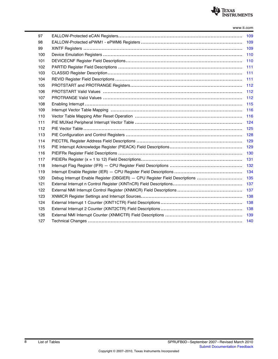
www.ti.com EALLOW-Protected eCAN Registers.................................................................................. 109 EALLOW-Protected ePWM1 - ePWM6 Registers ................................................................... 109 XINTF Registers ......................................................................................................... 109 Device Emulation Registers ............................................................................................ 110 DEVICECNF Register Field Descriptions............................................................................. 110 PARTID Register Field Descriptions .................................................................................. 111 CLASSID Register Description......................................................................................... 111 REVID Register Field Descriptions .................................................................................... 111 PROTSTART and PROTRANGE Registers.......................................................................... 112 PROTSTART Valid Values ............................................................................................ 112 PROTRANGE Valid Values ............................................................................................ 112 Enabling Interrupt ........................................................................................................ 115 Interrupt Vector Table Mapping ....................................................................................... 116 Vector Table Mapping After Reset Operation ....................................................................... 116 PIE MUXed Peripheral Interrupt Vector Table ....................................................................... 124 PIE Vector Table ......................................................................................................... 125 PIE Configuration and Control Registers ............................................................................. 128 PIECTRL Register Address Field Descriptions ...................................................................... 129 PIE Interrupt Acknowledge Register (PIEACK) Field Descriptions................................................ 129 PIEIFRx Register Field Descriptions .................................................................................. 130 PIEIERx Register (x = 1 to 12) Field Descriptions................................................................... 131 Interrupt Flag Register (IFR) — CPU Register Field Descriptions ................................................ 132 Interrupt Enable Register (IER) — CPU Register Field Descriptions ............................................. 134 Debug Interrupt Enable Register (DBGIER) — CPU Register Field Descriptions .............................. 135 External Interrupt n Control Register (XINTnCR) Field Descriptions.............................................. 137 External NMI Interrupt Control Register (XNMICR) Field Descriptions ........................................... 137 XNMICR Register Settings and Interrupt Sources................................................................... 138 External Interrupt 1 Counter (XINT1CTR) Field Descriptions...................................................... 138 External Interrupt 2 Counter (XINT2CTR) Field Descriptions...................................................... 138 External NMI Interrupt Counter (XNMICTR) Field Descriptions ................................................... 139 Technical Changes ...................................................................................................... 140 97 98 99 100 101 102 103 104 105 106 107 108 109 110 111 112 113 114 115 116 117 118 119 120 121 122 123 124 125 126 127 8 List of Tables Copyright © 2007–2010, Texas Instruments Incorporated SPRUFB0D– September 2007–Revised March 2010 Submit Documentation Feedback
分享到:
收藏