Application Report
SPRA494
Implementation of Vector Control for
PMSM Using the TMS320F240 DSP
Michel Platnic
Abstract
Digital Signal Processor Solutions
This document presents a solution for controlling a permanent magnet synchronous motor using
the Texas Instruments (TI�) TMS320C24x digital signal processor (DSP). The new TMS320C24x
family of DSPs offers a cost-effective design of intelligent controllers for brushless motors that
can fulfill enhanced operations consisting of fewer system components, lower system cost, and
increased performances. The control method presented relies on the field orientated control
(FOC) together with a field-weakening operation. This algorithm maintains efficiency in a wide
range of speeds, above nominal speed, and takes into consideration torque changes with
transient phases by controlling the flux directly from the rotor coordinates. This report describes a
practical solution and corresponding results.
Contents
Introduction ......................................................................................................................................................3
Application Description.....................................................................................................................................4
Convention.......................................................................................................................................................9
FOC Software Organization ...........................................................................................................................11
Parameter Adaptation ....................................................................................................................................15
Field Weakening ............................................................................................................................................27
Results ...........................................................................................................................................................31
User Interface ................................................................................................................................................36
Conclusion .....................................................................................................................................................36
References.....................................................................................................................................................37
Appendix A. TMS320F240 FOC Software ....................................................................................................37
Appendix B. Linker File .................................................................................................................................64
Appendix C. Sinewave Table ........................................................................................................................65
Appendix D. Qbasic User Interface...............................................................................................................67
Figures
Figure 1.
Figure 2.
Figure 3.
Figure 4.
Figure 5.
Three-Phase Synchronous Motor with One Permanent Magnet Pair Pole Rotor .......................3
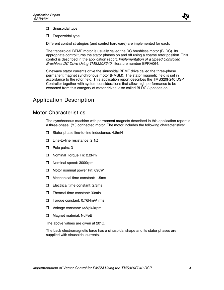
Three BEMF Waveforms at 1000rpm .........................................................................................5
Inverter Topology........................................................................................................................5
Top View of TMS320F240 EVM Board.......................................................................................6
ACPM750E with a MCK240........................................................................................................7
Digital Signal Processing Solutions
December 1998
�
Figure 6.
Stator Current and Magnet Flux Space Vectors in the d,q Rotating Reference Frame and its
Relationship with the a, b, c Stationary Reference Frame ...........................................................8
PMSM Control with Field Orientation..........................................................................................8
Figure 7.
Format Correspondence Diagram ............................................................................................11
Figure 8.
Figure 9.
FOC Software Initialization and Operating System...................................................................11
Figure 10. General Software Flowchart .....................................................................................................12
Figure 11.
Control Algorithm Timing ..........................................................................................................12
Figure 12. Waiting Loop/User Interface .....................................................................................................13
Control Routine Block Diagram ................................................................................................14
Figure 13.
Block Diagram of the FOC Including Closed Loop Field Weakening Control ...........................15
Figure 14.
Figure 15.
Current Measurement Chain ....................................................................................................17
Current Sensing Interface Block Diagram.................................................................................17
Figure 16.
Sensed Current Values before Scaling.....................................................................................18
Figure 17.
SinG Calculation Using the Sine Look-Up Table .......................................................................23
Figure 18.
Figure 19.
SVPWM, Vectors and Sectors..................................................................................................25
Figure 20 Assigning the Right Duty Cycle to the Right Motor Phase .............................................................27
Figure 21.
Field Weakening Real Operation..............................................................................................27
Figure 22. Maximum and Nominal Torque vs Speed.................................................................................28
Field Weakening Voltage Constraints.......................................................................................29
Figure 23.
Figure 24.
Control Range of a PMSM in Steady State...............................................................................29
Figure 25.
Field Weakening Function Structure.........................................................................................30
Figure 26. Speed Transient from 0 rpm to 1000 rpm .....................................................................................32
Speed Transient from 0 rpm to 3000 rpm at Nominal Torque...................................................33
Figure 27.
Speed Transient from -1000 rpm to 1000 rpm at Nominal Torque ...........................................34
Figure 28.
Speed Transient from 0 rpm to 3000 rpm Graph1 without Torque, Graph2 with 1.1Nm...........34
Figure 29.
Figure 30.
Steady-State Speed at Nominal Speed and 33% Above at Maximal Torque ...........................35
Speed/Torque Plot....................................................................................................................35
Figure 31.
Figure 32.
User Screen..............................................................................................................................36
�
Application Report
SPRA494
Introduction
The Texas Instruments TMS320F240 DSP Controller is suitable for a wide range of
motor drives. The TMS320F240 provides a single chip solution by integrating on-chip a
high computational power along with all of the peripherals necessary for electrical motor
control. The main effect of this combination is the possible implementation of advanced
controls such as vector control. High range controls increase system performance,
reliability, efficiency, and cost. This application report describes a speed control
implemented on a TMS320F240 for a three-phase Permanent Magnet drive with
sinewave currents.
The AC Permanent Magnet Motor
There are mainly two kinds of three-phase synchronous motors (SM). One uses rotor
windings fed from the stator. The other one uses permanent magnets.
A motor fitted out with rotor windings requires brushes to obtain its current supply and
generate the rotor flux. The contacts are, in this case, made of rings and do not have any
commutator segment. The lifetime of both the brushes and the motor may be similar. The
drawbacks of this structure – maintenance needs and lower reliability – are then limited.
Replacing common rotor field windings and pole structure with permanent magnets put
the motor into the category of brushless motors. It is possible to build brushless
permanent magnet motors with any even number of magnet poles. The use of magnets
enables an efficient use of the radial space and replaces the rotor windings, therefore
suppressing the rotor copper losses. Advanced magnet materials permit a considerable
reduction in motor dimensions while maintaining a very high power density.
Figure 1. Three-Phase Synchronous Motor with One Permanent Magnet Pair Pole
Rotor
C
B
A
N
S
AA
B
C
The application studied in this report concerns the permanent magnet motor.
The Sinewave Currents
Two configurations of permanent magnet brushless motor drives are usually considered,
depending on the back-electromagnetic force (BEMF) waveform:
Implementation of Vector Control for PMSM Using the TMS320F240 DSP
3
�
Application Report
SPRA494
H Sinusoidal type
H Trapezoidal type
Different control strategies (and control hardware) are implemented for each.
The trapezoidal BEMF motor is usually called the DC brushless motor (BLDC). Its
appropriate control turns the stator phases on and off using a coarse rotor position. This
control is described in the application report, Implementation of a Speed Controlled
Brushless DC Drive Using TMS320F240, literature number BPRA064.
Sinewave stator currents drive the sinusoidal BEMF drive called the three-phase
permanent magnet synchronous motor (PMSM). The stator magnetic field is set in
accordance to the rotor field. This application report describes the TMS320F240 DSP
Controller together with system considerations that allow high performance to be
extracted from this category of motor drives, also called BLDC 3 phases-on.
Application Description
Motor Characteristics
The synchronous machine with permanent magnets described in this application report is
a three-phase (Y ) connected motor. The motor includes the following characteristics:
H Stator phase line-to-line inductance: 4.8mH
H Line-to-line resistance: 2.19
H Pole pairs: 3
H Nominal Torque Tn: 2.2Nm
H Nominal speed: 3000rpm
H Motor nominal power Pn: 690W
H Mechanical time constant: 1.5ms
H Electrical time constant: 2.3ms
H Thermal time constant: 30min
H Torque constant: 0.76Nm/A rms
H Voltage constant: 65Vpk/krpm
H Magnet material: NdFeB
The above values are given at 20�C.
The back electromagnetic force has a sinusoidal shape and its stator phases are
supplied with sinusoidal currents.
Implementation of Vector Control for PMSM Using the TMS320F240 DSP
4
�
Application Report
SPRA494
Figure 2. Three BEMF Waveforms at 1000rpm
The Power Electronics Hardware
The ACPM750E used in this application is built around the 750W POWIRTRAIN integrated
power stage IRPT1056C from International Rectifier, which includes a rectifier bridge and
a three-phase ultra-fast IGBT inverter.
The converter topology supports either sinusoidal currents (three phases ON operation)
or direct currents (two phases ON operation). The first control is implemented in this
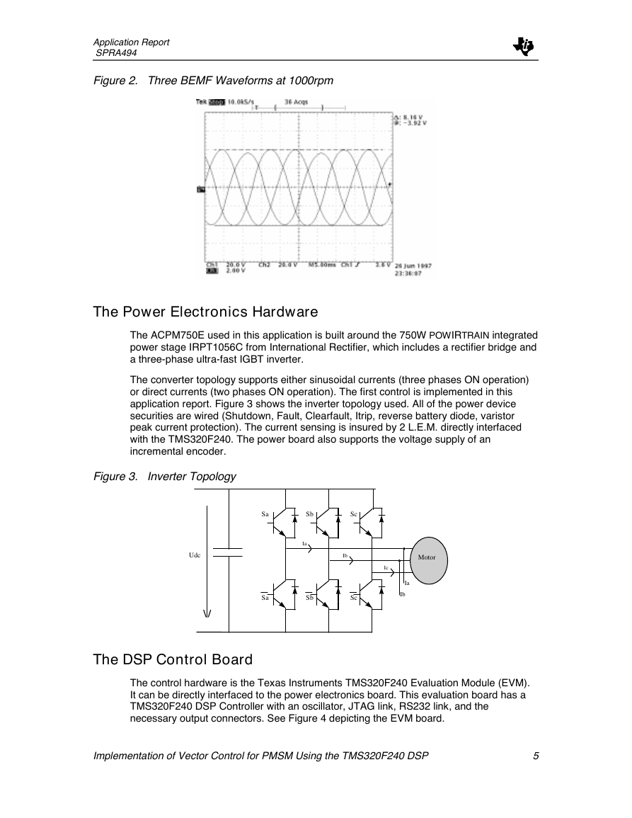
application report. Figure 3 shows the inverter topology used. All of the power device
securities are wired (Shutdown, Fault, Clearfault, Itrip, reverse battery diode, varistor
peak current protection). The current sensing is insured by 2 L.E.M. directly interfaced
with the TMS320F240. The power board also supports the voltage supply of an
incremental encoder.
Figure 3. Inverter Topology
Sa
Sb
Sc
Udc
Ib
Motor
Ia
Sa
Sb
Sc
Ic
Ia
Ib
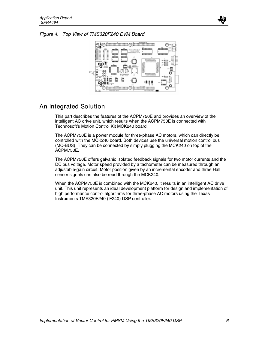
The DSP Control Board
The control hardware is the Texas Instruments TMS320F240 Evaluation Module (EVM).
It can be directly interfaced to the power electronics board. This evaluation board has a
TMS320F240 DSP Controller with an oscillator, JTAG link, RS232 link, and the
necessary output connectors. See Figure 4 depicting the EVM board.
Implementation of Vector Control for PMSM Using the TMS320F240 DSP
5
�
Application Report
SPRA494
Figure 4. Top View of TMS320F240 EVM Board
An Integrated Solution
This part describes the features of the ACPM750E and provides an overview of the
intelligent AC drive unit, which results when the ACPM750E is connected with
Technosoft’s Motion Control Kit MCK240 board.
The ACPM750E is a power module for three-phase AC motors, which can directly be
controlled with the MCK240 board. Both devices use the universal motion control bus
(MC-BUS). They can be connected by simply plugging the MCK240 on top of the
ACPM750E.
The ACPM750E offers galvanic isolated feedback signals for two motor currents and the
DC bus voltage. Motor speed provided by a tachometer can be measured through an
adjustable-gain circuit. Motor position given by an incremental encoder and three Hall
sensor signals can also be read through the MCK240.
When the ACPM750E is combined with the MCK240, it results in an intelligent AC drive
unit. This unit represents an ideal development platform for design and implementation of
high performance control algorithms for three-phase AC motors using the Texas
Instruments TMS320F240 (‘F240) DSP controller.
Implementation of Vector Control for PMSM Using the TMS320F240 DSP
6
�
Application Report
SPRA494
Figure 5. ACPM750E with a MCK240
Field Orientated Control Principle
The vector control principle consists of controlling the angle and amplitude components
of the stator field. For ease of motor equation representation, the components of the
stator current are represented in a rotating reference frame d,q aligned with the rotor
axis, i.e., with the magnet flux. The motor torque for a permanent magnet machine
depends only on the quadrature (q) current component (torque component). In this case,
the most convenient control strategy is to set to zero the direct (d ) current component to
minimize the torque vs. current ratio and then increase the motor (and converter)
efficiency. The control of current components requires the knowledge of the
instantaneous rotor position.
Implementation of Vector Control for PMSM Using the TMS320F240 DSP
7
�
Application Report
SPRA494
Figure 6. Stator Current and Magnet Flux Space Vectors in the d,q Rotating Reference
Frame and its Relationship with the a, b, c Stationary Reference Frame
b
q
mRM
is
i
sq
sdi
r
d
mRi
a
STATOR
ROTOR
c
The control scheme proposed for the PM synchronous motor drive is shown in Figure 7.
It is based on the vector control principle arranged in the d,q rotating frame introduced in
the TI application report, DSP Solution for Permanent Magnet Asynchronous Motor,
literature number BPRA044. Two of three motor phase currents are measured with
current sensor, the Clarke transform is applied and then modifies a three-phase system
into a two-phase orthogonal system. The output of this transformation is indicated as i=S
and i>S. These two components of the stator current are the input of the Park transform
that gives the stator current in the d,q rotating reference frame. Note that this second
transformation needs the rotor flux position. The quadrature current component is
regulated to the reference value given by the speed controller, while the direct current
component is set to zero to minimize the current vs. torque ratio of the motor. The
outputs of the current controllers, representing the voltage references, are then
impressed to the motor using the Space Vector Modulation technique, once an inverse
transformation from the rotating to the fixed stator reference is performed. An outer
speed control loop completes the scheme. All of the controllers used are standard PI
regulators. Figure 7 shows this basic scheme.
Figure 7. PMSM Control with Field Orientation
PI
iqSr
-
idSr
-
nc
-
n
vqSr
vdSr
PI
PI
d,q
=�>
iqS
idS
d,q
=�>
v=Sr
v>Sr
G
i=S
i>S
SV
PWM
PWM1
PWM2
PWM3
ia
ib
=�>
a,b,c
Implementation of Vector Control for PMSM Using the TMS320F240 DSP
8
�



 2023年江西萍乡中考道德与法治真题及答案.doc
 2012年重庆南川中考生物真题及答案.doc
 2013年江西师范大学地理学综合及文艺理论基础考研真题.doc
 2020年四川甘孜小升初语文真题及答案I卷.doc
 2020年注册岩土工程师专业基础考试真题及答案.doc
 2023-2024学年福建省厦门市九年级上学期数学月考试题及答案.doc
 2021-2022学年辽宁省沈阳市大东区九年级上学期语文期末试题及答案.doc
 2022-2023学年北京东城区初三第一学期物理期末试卷及答案.doc
 2018上半年江西教师资格初中地理学科知识与教学能力真题及答案.doc
 2012年河北国家公务员申论考试真题及答案-省级.doc
 2020-2021学年江苏省扬州市江都区邵樊片九年级上学期数学第一次质量检测试题及答案.doc
 2022下半年黑龙江教师资格证中学综合素质真题及答案.doc