logo资料库

aspeed AST2500/AST2520 v16去水印 datasheet.pdf

第1页 / 共833页
第2页 / 共833页
第3页 / 共833页
第4页 / 共833页
第5页 / 共833页
第6页 / 共833页
第7页 / 共833页
第8页 / 共833页
资料共833页,剩余部分请下载后查看
I Functional Specification
1 General Information
1.1 Introduction
1.2 Chip Architecture
1.3 Summary of Feature Set
1.3.1 Package
1.3.2 Design for Testability
1.3.3 PCI-Express 2.0 Bus Device Controller (AST2520 Excluded)
1.3.4 PCI-Express 2.0 Bus Master Controller (AST2520 Excluded)
1.3.5 VGA Display Controller (AST2520 Excluded)
1.3.6 64-bit 2D Graphics Accelerator (AST2520 Excluded)
1.3.7 SOC Display Controller (AST2520 Excluded)
1.3.8 DDR3L/DDR4 SDRAM Controller
1.3.9 Embedded ARM1176JZS CPU
1.3.10 Embedded Coprocessor CPU (AST2520 Excluded)
1.3.11 Video Compression Engine (AST2520 Excluded)
1.3.12 Internal SRAM
1.3.13 Battery Backed SRAM
1.3.14 System Control Unit (SCU)
1.3.15 AHB Controller (AHBC)
1.3.16 Interrupt Controller (VIC)
1.3.17 Firmware SPI Memory Controller (FMC)
1.3.18 SPI Master Controller (SPI)
1.3.19 SD/SDIO/eMMC Host Controller
1.3.20 USB2.0 Virtual Hub Controller
1.3.21 USB1.1 HID Device Controller
1.3.22 USB2.0 Host Controller
1.3.23 USB1.1 Host Controller
1.3.24 10/100/1000 Mbps Fast Ethernet MAC
1.3.25 I2C/SMBus Serial Interface Controller
1.3.26 GPIO Controller
1.3.27 Master Serial GPIO Controller
1.3.28 Slave Serial GPIO Monitor
1.3.29 UART (16550)
1.3.30 Timer
1.3.31 Watchdog Timer (WDT)
1.3.32 Real Time Clock (RTC)
1.3.33 LPC Bus Interface
1.3.34 eSPI Interface
1.3.35 System SPI Flash Controller
1.3.36 Super I/O Controller
1.3.37 Hash & Crypto Engine
1.3.38 Memory Integrity Check (MIC) Engine
1.3.39 ADC Controller
1.3.40 PWM Controller
1.3.41 Fan Tachometer Controller
1.3.42 PECI Controller
1.3.43 JTAG Master Controller
1.3.44 MCTP Controller (AST2520 Excluded)
1.3.45 MSI Controller (AST2520 Excluded)
1.3.46 X-DMA Controller (AST2520 Excluded)
1.3.47 Software Specifications
1.4 Features Comparison (AST2500/AST2400/AST2300)
1.5 Features Comparison (AST2520/AST1250/AST1050)
1.6 Features Comparison (AST2500/AST2510/AST2520)
1.7 Features Comparison (AST2500/AST2520/AST2530)
1.8 Applications
1.8.1 Flash Interface Architecture
1.8.2 Remote BIOS Update
1.8.3 UART Interface Application
1.8.4 Display Output Interface
1.8.5 USB Port Configuration
1.9 Firmware Update Methods
1.9.1 Update through PCIe (AST2500/AST2510/AST2530)
1.9.2 Update through LPC (AST2500/AST2510/AST2520/AST2530)
1.9.3 Update through UART (AST2500/AST2510/AST2520/AST2530)
1.9.4 Update through LAN by Firmware (AST2500/AST2520/AST2530)
1.9.5 Update through SPI programmer (AST2500/AST2510/AST2520/AST2530)
2 Pin & I/O Related Specification
2.1 Pin Description
2.1.1 Not Available Pins for AST2520
2.2 Ball Map
2.3 Hardware/Software Strap Definition
2.3.1 Step 1: Load from dedicated strap pins
2.3.2 Step 2: Hardware Strap – Load from the optional strap pins
2.3.3 Step 3: Firmware strap – Load from the Firmware SPI flash
2.3.4 Hardware strap configuration method
2.3.5 Application Note 3: Hardware Strap Configuration
2.4 Digital Video Interface
2.4.1 Video Mode
2.4.2 Digital Video Single Edge Data Mode
2.4.3 Digital Video Dual Edge Display Output Data Mode : 12 Bits Interface
2.5 GPIO Summary
2.5.1 GPIO Table
2.5.2 GPIO Pass Through
2.6 Serial GPIO Master
2.6.1 Timing Waveform
2.6.2 Example Verilog Code for SGPIO Shifter
2.7 Serial GPIO Slave Monitor
3 Electrical Specifications
3.1 Absolute Maximum Ratings
3.2 Recommended Operating Conditions
3.3 Input Overshoot/Undershoot Tolerance
3.4 Input Ringback Tolerance
3.5 ESD Capability
3.6 Power Consumption
3.7 Power Up Sequence
3.8 Power Down Sequence for Firmware
3.9 I/O DC Electrical Specification
3.9.1 3.3V CMOS I/O Parameters
3.9.2 2.5V CMOS I/O Parameters
3.9.3 1.8V CMOS I/O Parameters
3.9.4 DDR3L I/O Parameters
3.9.5 DDR4 I/O Parameters
3.9.6 DAC I/O Parameters
3.9.7 ADC I/O Parameters
3.9.8 USB I/O Parameters
3.9.9 Battery Backed SRAM Parameters
3.9.10 PECI I/O Parameters
3.9.11 RGMII/RMII/NCSI I/O Parameters
3.10 AC Timing Specification
3.10.1 Reference Clock Input
3.10.2 LPC Interface
3.10.3 RGMII/RMII/NCSI Interface
3.10.4 DDR3/DDR4 Interface
3.10.5 Video Interface Input/Output: Single Edge
3.10.6 Video Interface Output: Dual Edge
3.10.7 SPI Master Interface
3.10.8 eSPI Slave Interface
3.10.9 SPI Pass-through Propagation Delay
3.10.10 JTAG Master Interface
3.10.11 I2C/SMBus Interface
3.10.12 SD/eMMC Interface
3.10.13 SGPIO Master Interface
3.10.14 SGPIO Slave Interface
3.10.15 Strap Input Interface
3.11 Thermal Specification (Simulation Result)
3.11.1 Terminology
3.11.2 Testing Conditions
3.11.3 Thermal Data
3.11.4 Substrate Material Properties
4 Package Information
4.1 SMT Soldering Reflow Chart
II Firmware Programming Guide
5 Multi-function Pins Mapping and Control
5.1 Function 1-2
5.2 Function 3-4
5.3 Pin Function Configuration
6 Reset Source Table
6.1 Function Level Reset Source Table
6.2 Register Level Reset Source Table
7 Memory Space Allocation Table
7.1 ARM Address Space Mapping
7.2 In-compatible List to AST2400
7.3 Coprocessor Address Space Mapping
7.4 VGA Memory Space map to ARM Memory Space
8 Interrupt Source Table
9 Major Firmware Programming Change List
9.1 Application Note 1: Firmware Programming Note for CLKIN=25MHz
9.2 Application Note 2: I2C DMA and UHCI limitation
10 Firmware Boot Up Sequence
11 UART Debug Interface
III Function Registers
12 AHB Bus Controller
12.1 Overview
12.2 Features
12.3 Registers : Base Address = 0x1E60:0000
12.4 Programming Guide
12.4.1 Enable Polling
13 Firmware SPI Memory Controller
13.1 Overview
13.2 Features
13.2.1 NOR type flash supporting features
13.2.2 SPI type flash supporting features
13.2.3 Alternate (2nd) Boot Function
13.3 Timing Definition
13.4 Registers : Base Address = 0x1E62:0000
13.5 Programming Guide
13.5.1 DMA Mode
13.5.2 DMA CheckSum Calculation Mode
13.5.3 SPI Timing Calibration Sequence
13.5.4 Address Continuity Rule
14 SPI Flash Controller
14.1 Overview
14.2 Registers : Base Address = 0x1E63:x000
15 Memory Integrity Check Controller
15.1 Overview
15.2 Features
15.3 Registers : Base Address = 0x1E64:0000
15.4 Page Control Bits
15.5 Control Buffer Format
15.6 Checksum Buffer Format
15.7 Porgramming Sequence
15.7.1 Parameter Definition
15.7.2 MIC Engine Initiation (DRAM 256M Byte Address Mode)
15.7.3 MIC Engine Initiation (DRAM 1G Byte Address Mode)
15.7.4 Start Page CheckSum Process
15.7.5 Stop Page CheckSum Process (DRAM 256M Byte Address Mode)
15.7.6 Stop Page CheckSum Process (DRAM 1G Byte Address Mode)
15.8 Interrupt Behavior
16 10/100/1G Ethernet MAC Controller
16.1 Overview
16.2 Features
16.3 Registers :
16.4 Function Description
16.4.1 Transmit Descriptor
16.4.2 Receive Descriptor
16.4.3 Transmitting Packet
16.4.4 Receiving Packet
16.4.5 Ethernet Address Filtering
16.4.6 MII Management Interface
16.5 Initialization
16.5.1 Frame Transmitting Procedure
16.5.2 Frame Receiving Procedure
17 USB2.0 Virtual Hub Controller
17.1 Overview
17.2 Features
17.3 Procedure to enable USB2.0 Hub port
17.3.1 Procedure to enable USB2.0 eye diagram measurement
17.4 Registers : Base Address = 0x1E6A:0000
17.4.1 Address Definition
17.4.2 Root/Global Register Definition
17.4.3 Device #1 | #5 Register Definition
17.4.4 Programmable Endpoint #0 | #14 Register Definition
17.4.5 Programmable Endpoint DMA Descriptor Definition
17.4.6 Register Reset Table
17.5 Software Programming Guide
17.5.1 Reset Control
17.5.2 Initialization Sequence
17.5.3 Set Device Address
17.5.4 Response STALL
17.5.5 Programmable Endpoint OUT Transfer Finish Check
17.5.6 Prevent a Transient Read Pointer Value
17.5.7 Procedure to enable Interrupt
17.5.8 OUT Direction Endpoint Maximum Packet Size Setting
18 USB2.0 Device Controller (Removed)
19 USB2.0/1.1 Host Controller
19.1 Overview
19.2 UHCI Features
19.3 EHCI Features
19.4 Procedure to enable USB Host port
19.4.1 USB2.0 Host port 1
19.4.2 USB2.0 Host port 2
19.4.3 UHCI controller
19.5 UHCI Registers : Base Address = 0x1E6B:0000
19.6 EHCI Registers
20 Interrupt Controller
20.1 Overview
20.1.1 ARM CPU Interrupt Controller
20.1.2 System LPC Interrupt Controller (SVIC)
20.1.3 Coprocessor Interrupt Controller (CVIC)
20.2 Features
20.3 VIC Registers : Base Address = 0x1E6C:0000
20.4 SVIC Registers : Base Address = 0x1E6C:1000
20.5 CVIC Registers : Base Address = 0x1E6C:2000
21 SDRAM Memory Controller
21.1 Overview
21.1.1 Features
21.1.2 ECC Features
21.1.3 Register Summary
21.2 Fixed Priority DRAM Request
21.3 Registers: Base Address = 0x1E6E:0000
21.4 Address Arrangement
21.4.1 Address Translation
21.5 Self Refresh Command Sequence
21.5.1 Enter Self Refresh
21.5.2 Exit Self Refresh
22 USB1.1 HID Controller
22.1 Overview
22.2 Features
22.3 Procedure to enable USB1.1 Device port
22.4 Registers : Base Address = 0x1E6E:1000
22.5 Software Programming Guide
23 System Control Unit (SCU)
23.1 Overview
23.2 Registers : Base Address = 0x1E6E:2000
24 Hash & Crypto Engine (HACE)
24.1 Overview
24.2 Features
24.3 Registers : Base Address = 0x1E6E:3000
24.4 RSA Buffer Format in Extended SRAM : Extended SRAM Base Address = 0x1E72:0000
24.5 Crypto Context Buffer Format
24.5.1 RC4 (272 Bytes)
24.5.2 AES-128 (192 Bytes)
24.5.3 AES-192 (224 Bytes)
24.5.4 AES-256 (256 Bytes)
24.5.5 DES (40 Bytes)
24.6 Hash Function Programming Sequence
24.6.1 Parameter Definition
24.6.2 MD5/SHA1/SHA224/SHA256
24.6.3 HMAC MD5/SHA1/SHA224/SHA256
24.6.4 Accumulative Mode
24.7 Command Queue Data Format
25 JTAG Master Controller
25.1 Overview
25.2 Features
25.3 Registers : Base Address = 0x1E6E_4000
25.4 Operation
25.4.1 Reset State Machine
25.4.2 Instruction Transmission
25.4.3 Data Transmission
25.5 Application Note
25.5.1 Introduction
25.5.2 Hardware Mode
25.5.3 Software Mode
26 SOC Display Controller (GFX)
26.1 Overview
26.2 Features
26.3 SOC Display Controller Registers
27 X-DMA Controller
27.1 Overview
27.2 Features
27.3 Registers
27.4 Command Format
27.5 Clearing and Setting Procedure
27.5.1 Host Command Queue in Dirty Frame Clearing Procedure
27.5.2 Down-stream in Dirty Frame Clearing Procedure
27.5.3 Host Command Queue Read/Write Pointer Setting Procedure
27.5.4 BMC Command Queue Read/Write Pointer Setting Procedure
27.5.5 VGA Command Queue Read/Write Pointer Setting Procedure
28 MCTP Controller
28.1 Overview
28.2 Features
28.3 Registers : Base Address = 0x1E6E_8000
28.4 Command
28.4.1 TX command
28.4.2 RX command
28.5 Operation
28.5.1 Send Packet
28.5.2 Receive Packet
29 ADC Controller
29.1 Overview
29.2 Features
29.3 Registers : Base Address = 0x1E6E_9000
29.4 Operation
29.4.1 Initialize Sequence
29.4.2 Compensating Sensing Method
29.4.3 Voltage Sense Method
30 APB to PCIe Bus Bridge
30.1 Overview
30.2 Features
30.3 Registers : Base Address = 0x1E6F_0000
30.4 Operation
30.4.1 Send Packet
30.4.2 Receive Packet
31 eSPI Controller
31.1 Overview
31.2 Features
31.3 Registers : Base Address = 0x1E6E_E000
31.4 Programming Guide
31.4.1 Address of Peripheral Channel Rx Packet.(MemWR and MemRD)
31.4.2 Process of receiving packet
31.4.3 Procedure to sending packet
32 Battery Backed SRAM
32.1 Overview
33 Video Engine (VE)
33.1 Overview
33.2 Features
33.3 Registers : Base Address = 0x1E70:0000
34 SRAM Memory Buffer
34.1 Overview
35 SD/SDIO Host Controller
35.1 Overview
35.2 Features
35.3 Registers : Base Address = 0x1E74:0000
35.4 Operation
35.4.1 Card Detection Method
36 GPIO Controller
36.1 Overview
36.2 Features
36.2.1 Parallel GPIO
36.2.2 Serial GPIO
36.2.3 SGPIO Slave Monitor
36.3 Registers : Base Address = 0x1E78:0000
36.3.1 Parallel GPIO
36.3.2 Serial GPIO
36.3.3 SGPIO Slave
36.4 Programming Guide
36.4.1 LPC port80h direct to GPIO
36.4.2 LPC port80h direct to SGPIO
36.4.3 Parallel GPIO output driving mode
37 Real Time Clock (RTC)
37.1 Overview
37.2 Features
37.3 Registers : Base Address = 0x1E78:1000
37.4 Operation
37.4.1 Initialize Sequence
37.4.2 Alarm Mode
38 Timer Controller
38.1 Overview
38.2 Features
38.3 Registers : Base Address = 0x1E78:2000
38.4 Operation
38.5 Programming Note
38.5.1 Interrupt Generation
38.5.2 Programmable Duty Cycle Pulse Generation
38.5.3 Programmable Delay Sequence Pulse Generation
39 UART Controller (16550)
39.1 Overview
39.2 Features
39.3 Registers
39.3.1 UART_DLL/UART_DLH
40 UART DMA
40.1 Overview
40.2 Features
40.3 Registers : Base Address = 0x1E78:2000
41 Watchdog Timer
41.1 Overview
41.2 Features
41.3 Registers : Base Address = 0x1E78:5000
41.4 Operation
41.4.1 Enable watchdog reset
41.4.2 Enable watchdog pulse output
41.4.3 Enable watchdog interrupt output
41.5 Programming Note
41.5.1 PCLK frequency requirement
42 PWM & Fan Tacho Controller
42.1 Overview
42.2 Features
42.3 Registers : Base Address = 0x1E78:6000
43 Virtual UART
43.1 Overview
43.2 Features
43.3 VUART Registers : Base Address = 0x1E78:7000
43.4 PUART Registers : Base Address = 0x1E78:8000
44 LPC Controller
44.1 Overview
44.2 Features
44.3 Registers : Base Address = 0x1E78:9000
45 LPC+ Controller
45.1 Overview
45.2 Feature
45.3 Registers : Base Address = 0x1E6E_C000
45.4 Operation
45.4.1 Calibration
46 SuperIO Controller (SIO)
46.1 Overview
47 System Wake-Up Control (SWC)
47.1 Overview
48 MailBox Controller (MBOX)
48.1 Overview
49 I2C/SMBus Controller
49.1 Overview
49.2 Features
49.2.1 I2C Master - all 14 buses
49.2.2 I2C Slave - all 14 buses
49.2.3 SMBus - all 14 buses
49.2.4 General
49.3 Migration from AST2300 to AST2400
49.4 Migration from AST2400 to AST2500
49.5 Timing Definition
49.5.1 Clock Setting Table
49.6 Registers : Base Address = 0x1E78:A000
49.6.1 Address Definition
49.6.2 Global Register Definition
49.6.3 Device Register Definition
50 PECI Controller
50.1 Overview
50.2 Features
50.3 Registers : Base Address = 0x1E78:B000
51 PCIe Host Controller
51.1 Overview
51.2 Features
51.3 Registers : Base Address = 0x1E6E:D000
IV PCI Express Interface
52 PCI Express Controller
52.1 PCI Express Configuration Registers
52.2 Type 1 Configuration Registers
52.3 Message signaled interrupts
52.4 Power Management Capability Structure
52.5 PCI Express Capability Structure
52.6 SSID/SSVID Capability Structure
53 PCI Bus Controller (P-Bus)
53.1 Overview
53.2 Features
54 VGA Display Controller
54.1 Overview
54.2 Features
54.3 Registers
54.4 Sequential Controller Registers
54.5 CRT Controller Registers
54.6 Graphics Controller Registers
54.7 Attribute Controller Registers
54.8 RAMDAC Registers
54.9 Extended CRT Registers
55 2D Graphics Engine (G2D)
55.1 Overview
55.2 Features
55.3 2D Engine Registers
56 Graphics Hardware Cursor
56.1 Features
56.2 Register Definition
56.3 Cursor Shape Structure Definition
56.3.1 Monochrome Cursor Format (AND-XOR-RGB444 pixel format)
56.3.2 Color Cursor Format (ARGB4444 pixel format)
57 P-Bus to AHB Bridge (P2A)
57.1 Overview
57.2 Registers : Base Address = MMIOBASE
58 Message Signaled Interrupts (MSI)
58.1 Overview
58.2 Features
58.3 Operation
58.3.1 Interrupt Table
58.3.2 Message Signaled Interrupts
58.3.3 Virtual INTx
59 PCIe BMC Device
59.1 Overview
59.2 Features
AST2500/AST2520 Integrated Remote Management Processor A2 Datasheet Version 1.6 May 12, 2017 ASPEED Technology Inc. retains the right to make changes to its products or specifications. While the information furnished herein is held to be accurate and reliable, no responsibility will be assumed by ASPEED Technology for its use. Furthermore, the information contained herein does not convey to the purchaser of microelectronic devices any license under the patent right of any manufactures. ASPEED products are not intended for use in life support products where failure of an ASPEED product could reasonably be expected to result in death or personal injury. Anyone using an ASPEED product in such an application without express written consent of an officer of ASPEED does so at their own risk, and agrees to fully indemnify ASPEED for any damages that may result from such use or sale. All other trademarks or register trademarks mentioned herein are the property of their respective holders. Headquarters 2F,No.15,Industry East Road 4.,Hsinchu Science Park, Hsinchu City 30077, Taiwan, R. O. C. TEL: 886-3-5789568 FAX: 886-3-5789586 http://www.ASPEEDtech.com Copyright c2017, ASPEED Technology Inc. All right reserved.
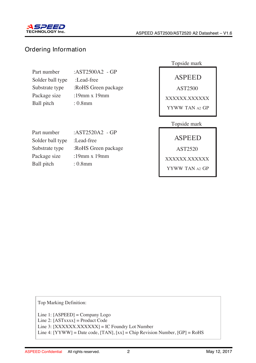
ASPEED AST2500/AST2520 A2 Datasheet – V1.6 Ordering Information Part number Solder ball type Substrate type Package size Ball pitch :AST2500A2 - GP :Lead-free :RoHS Green package :19mm x 19mm : 0.8mm Part number Solder ball type Substrate type Package size Ball pitch :AST2520A2 - GP :Lead-free :RoHS Green package :19mm x 19mm : 0.8mm Topside mark ASPEED AST2500 XXXXXX.XXXXXX YYWW TAN A2 GP Topside mark ASPEED AST2520 XXXXXX.XXXXXX YYWW TAN A2 GP Top Marking Definition: Line 1: [ASPEED] = Company Logo Line 2: [ASTxxxx] = Product Code Line 3: [XXXXXX.XXXXXX] = IC Foundry Lot Number Line 4: [YYWW] = Date code, [TAN], [xx] = Chip Revision Number, [GP] = RoHS ASPEED Confidential All rights reserved. 2 May 12, 2017
ASPEED AST2500/AST2520 A2 Datasheet – V1.6 Revision History Date Revision Description Jul. 04, 2014 Jan. 22, 2015 0.1 0.9 Jun. 22, 2015 1.0 Oct. 15, 2015 1.1 Mar. 30, 2016 1.2 May. 18, 2016 1.3 Jun. 07, 2016 1.31 Nov. 08, 2016 1.4 Jan. 09, 2017 1.5 May. 12, 2017 1.6 Initial draft. 1. Release for chip revision A1. 2. Add chip revision A1 migration list at next page. 3. Add per-pin function configuration table at Section 5.3. 4. Add Reset Source Table at Section 6. 5. Add USB ports configuration mode description at Section 1.8.5. 6. Add Firmware update methods description at Section 1.9. 7. Add Firmware boot up sequence diagram at Section 10. 8. Revise IV11D from 1.1V to 1.15V. 9. Add ESD specification. 10. Revise DACRSET external resistor value to 18KΩ. 1. Add CMOS IO 2.5V/1.8V DC spec. 2. Add feature of PCI-Express Master. 3. Rename power ball T11 from PV33D to MPLLAV33, this power ball requires isolated power rail with low noise. 4. Add specification for overshoot, undershoot, and ringback at section 3.3. 5. Add power consumption information at section 3.6. 6. Add DC electrical specification for DDR, USB, BSRAM at section 3.9. 7. Add AC electrical specification at section 3.10. 8. Add thermal specification at section 3.11. 9. Update firmware programming note at section 9. 10. Update the timing waveform of SGPIO master at section 2.6.1. 11. Add verilog example of SGPIO shifter at section 2.6.2. 12. Revise the pull up power of MAC TX strap pins. 13. Revise some values in the power up sequence at section 3.7. 1. Revise boot up sequence diagram at section 10. 2. Add registers specification of APB to PCIe Bus Bridge at section 30. 3. Add registers specification of PCIe Host Controller at section 51. 4. Add firmware related APnote of Application Note 1 and Application Note 2. 5. Add hardware related APnote or Application Note 3. 6. Rename ”Graphics Display Controller” to ”SOC Display Controller”. 7. Remove ”Graphics Display Controller” feature on AST2520. 8. Add architecture block diagram of AST2520 at Figure-2. 1. Release for chip revision A2. 2. Fix eSPI SUART1/SUART2 IRQ number issue. 3. Update chip hardware revision ID at SCU7C. 1. Revise ADC DC specification. 2. Add power down sequence for firmware at section 3.8. 1. Revise power down sequence for firmware at section 3.8. AST2510 do not require to care the power down sequence. 1. Revise reset function of SPI1/SPI2 controller at section 6.2. 2. Remove MACD0 and MACD4 at section 16. Please refer document E2500- 01 or Errata List. 3. Relax AC timing rise/fall time specification of RGMII, SPI, and eSPI. 4. Add recommended operating temperature of TC. 1. Add Strap input pins AC timing specification at section 3.10.15. 2. Remove USB portB USB2.0 Device Controller feature. Please refer docu- ment E2500-02 or Errata List. 1. Revise SPI master AC timing specification at section 3.10.7. 2. Revise eSPI AC timing specification at section 3.10.8. 3. Revise I2C AC timing specification at section 3.10.11. ASPEED Confidential All rights reserved. 3 to next page May 12, 2017
ASPEED AST2500/AST2520 A2 Datasheet – V1.6 4. Revise Overshoot timing specification at section 3.3. 5. Add MDC/MDIO AC timing specification at section 3.10.3. from previous page Text color definition 1. All new added features compare to AST2400/AST1250/AST1400 are highlighted by this color. 2. All different contents compare to previous release are highlighted by this color. 3. All important descriptions are highlighted by this color. 4. Removed features are highlighted by this style. AST2500 Migration List from A1 to A2 Functional Bugs in A1 that have fixed in A2 list 1. Fix eSPI SUART1/SUART2 IRQ number issue, change from 7/8 to 4/3. ASPEED Confidential All rights reserved. 4 May 12, 2017
ASPEED AST2500/AST2520 A2 Datasheet – V1.6 AST2500 - A2 Errata List 1. In Ethernet MAC controller IP, there are totally 8 MAC address filters, the MAC address filter #4 can not work properly, the affected registers are MACD0 and MACD4. • Solution: There is no hardware or software solution for this issue. Please do not use this MAC Instead, please use the other 7 MAC address filters if you need to filter certain address filter #4. MAC address. 2. In USB port B function – USB2.0 device controller, there is a logic failure on device address identification, thus it can not identify the correct device address and respond wrong packets to the host. • Solution: There is no hardware or software solution for this issue. Please do not use USB port B device controller function. ASPEED Confidential All rights reserved. 5 May 12, 2017
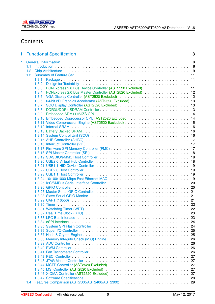
Contents I Functional Specification ASPEED AST2500/AST2520 A2 Datasheet – V1.6 8 1 General Information 8 8 1.1 Introduction . . . . . . . . . . . . . . . . . . . . . . . . . . . . . . . . . . . . . . . . . . . . . . . . 1.2 Chip Architecture . . . . . . . . . . . . . . . . . . . . . . . . . . . . . . . . . . . . . . . . . . . . . 9 1.3 Summary of Feature Set . . . . . . . . . . . . . . . . . . . . . . . . . . . . . . . . . . . . . . . . . 11 1.3.1 Package . . . . . . . . . . . . . . . . . . . . . . . . . . . . . . . . . . . . . . . . . . . . . . 11 1.3.2 Design for Testability . . . . . . . . . . . . . . . . . . . . . . . . . . . . . . . . . . . . . . . 11 . . . . . . . . . . . . . . . . 11 1.3.3 PCI-Express 2.0 Bus Device Controller (AST2520 Excluded) 1.3.4 PCI-Express 2.0 Bus Master Controller (AST2520 Excluded) . . . . . . . . . . . . . . . . 12 1.3.5 VGA Display Controller (AST2520 Excluded) . . . . . . . . . . . . . . . . . . . . . . . . . 12 1.3.6 64-bit 2D Graphics Accelerator (AST2520 Excluded) . . . . . . . . . . . . . . . . . . . . . 13 1.3.7 SOC Display Controller (AST2520 Excluded) . . . . . . . . . . . . . . . . . . . . . . . . . 13 1.3.8 DDR3L/DDR4 SDRAM Controller . . . . . . . . . . . . . . . . . . . . . . . . . . . . . . . . 13 1.3.9 Embedded ARM1176JZS CPU . . . . . . . . . . . . . . . . . . . . . . . . . . . . . . . . . 14 1.3.10 Embedded Coprocessor CPU (AST2520 Excluded) . . . . . . . . . . . . . . . . . . . . . 14 1.3.11 Video Compression Engine (AST2520 Excluded) . . . . . . . . . . . . . . . . . . . . . . . 15 1.3.12 Internal SRAM . . . . . . . . . . . . . . . . . . . . . . . . . . . . . . . . . . . . . . . . . . 16 1.3.13 Battery Backed SRAM . . . . . . . . . . . . . . . . . . . . . . . . . . . . . . . . . . . . . . 16 1.3.14 System Control Unit (SCU) . . . . . . . . . . . . . . . . . . . . . . . . . . . . . . . . . . . 16 . . . . . . . . . . . . . . . . . . . . . . . . . . . . . . . . . . . . . 17 1.3.15 AHB Controller (AHBC) 1.3.16 Interrupt Controller (VIC) . . . . . . . . . . . . . . . . . . . . . . . . . . . . . . . . . . . . 17 1.3.17 Firmware SPI Memory Controller (FMC) . . . . . . . . . . . . . . . . . . . . . . . . . . . . 17 1.3.18 SPI Master Controller (SPI) . . . . . . . . . . . . . . . . . . . . . . . . . . . . . . . . . . . 18 1.3.19 SD/SDIO/eMMC Host Controller . . . . . . . . . . . . . . . . . . . . . . . . . . . . . . . . 18 . . . . . . . . . . . . . . . . . . . . . . . . . . . . . . . . . 18 1.3.20 USB2.0 Virtual Hub Controller 1.3.21 USB1.1 HID Device Controller . . . . . . . . . . . . . . . . . . . . . . . . . . . . . . . . . 19 1.3.22 USB2.0 Host Controller . . . . . . . . . . . . . . . . . . . . . . . . . . . . . . . . . . . . . 19 1.3.23 USB1.1 Host Controller . . . . . . . . . . . . . . . . . . . . . . . . . . . . . . . . . . . . . 19 1.3.24 10/100/1000 Mbps Fast Ethernet MAC . . . . . . . . . . . . . . . . . . . . . . . . . . . . . 19 1.3.25 I2C/SMBus Serial Interface Controller . . . . . . . . . . . . . . . . . . . . . . . . . . . . . 20 . . . . . . . . . . . . . . . . . . . . . . . . . . . . . . . . . . . . . . . . . 20 1.3.26 GPIO Controller 1.3.27 Master Serial GPIO Controller . . . . . . . . . . . . . . . . . . . . . . . . . . . . . . . . . 21 1.3.28 Slave Serial GPIO Monitor . . . . . . . . . . . . . . . . . . . . . . . . . . . . . . . . . . . 21 . . . . . . . . . . . . . . . . . . . . . . . . . . . . . . . . . . . . . . . . . . 21 1.3.29 UART (16550) 1.3.30 Timer . . . . . . . . . . . . . . . . . . . . . . . . . . . . . . . . . . . . . . . . . . . . . . . 22 1.3.31 Watchdog Timer (WDT) . . . . . . . . . . . . . . . . . . . . . . . . . . . . . . . . . . . . . 22 1.3.32 Real Time Clock (RTC) . . . . . . . . . . . . . . . . . . . . . . . . . . . . . . . . . . . . . 23 1.3.33 LPC Bus Interface . . . . . . . . . . . . . . . . . . . . . . . . . . . . . . . . . . . . . . . . 23 1.3.34 eSPI Interface . . . . . . . . . . . . . . . . . . . . . . . . . . . . . . . . . . . . . . . . . . 24 1.3.35 System SPI Flash Controller . . . . . . . . . . . . . . . . . . . . . . . . . . . . . . . . . . 24 1.3.36 Super I/O Controller . . . . . . . . . . . . . . . . . . . . . . . . . . . . . . . . . . . . . . . 25 1.3.37 Hash & Crypto Engine . . . . . . . . . . . . . . . . . . . . . . . . . . . . . . . . . . . . . . 25 1.3.38 Memory Integrity Check (MIC) Engine . . . . . . . . . . . . . . . . . . . . . . . . . . . . . 26 1.3.39 ADC Controller . . . . . . . . . . . . . . . . . . . . . . . . . . . . . . . . . . . . . . . . . . 26 . . . . . . . . . . . . . . . . . . . . . . . . . . . . . . . . . . . . . . . . . 26 1.3.40 PWM Controller 1.3.41 Fan Tachometer Controller . . . . . . . . . . . . . . . . . . . . . . . . . . . . . . . . . . . 26 1.3.42 PECI Controller . . . . . . . . . . . . . . . . . . . . . . . . . . . . . . . . . . . . . . . . . . 27 1.3.43 JTAG Master Controller . . . . . . . . . . . . . . . . . . . . . . . . . . . . . . . . . . . . . 27 1.3.44 MCTP Controller (AST2520 Excluded) . . . . . . . . . . . . . . . . . . . . . . . . . . . . . 27 . . . . . . . . . . . . . . . . . . . . . . . . . . . . . . 27 1.3.45 MSI Controller (AST2520 Excluded) 1.3.46 X-DMA Controller (AST2520 Excluded) . . . . . . . . . . . . . . . . . . . . . . . . . . . . 27 1.3.47 Software Specifications . . . . . . . . . . . . . . . . . . . . . . . . . . . . . . . . . . . . . 28 . . . . . . . . . . . . . . . . . . . . . . . . 29 1.4 Features Comparison (AST2500/AST2400/AST2300) ASPEED Confidential All rights reserved. 6 May 12, 2017
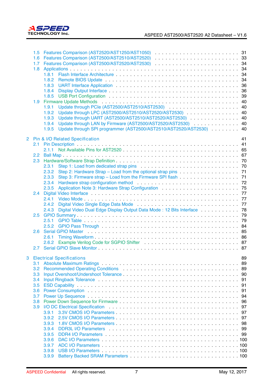
ASPEED AST2500/AST2520 A2 Datasheet – V1.6 . . . . . . . . . . . . . . . . . . . . . . . . 31 1.5 Features Comparison (AST2520/AST1250/AST1050) . . . . . . . . . . . . . . . . . . . . . . . . 33 1.6 Features Comparison (AST2500/AST2510/AST2520) 1.7 Features Comparison (AST2500/AST2520/AST2530) . . . . . . . . . . . . . . . . . . . . . . . . 34 1.8 Applications . . . . . . . . . . . . . . . . . . . . . . . . . . . . . . . . . . . . . . . . . . . . . . . . 34 1.8.1 Flash Interface Architecture . . . . . . . . . . . . . . . . . . . . . . . . . . . . . . . . . . . 34 1.8.2 Remote BIOS Update . . . . . . . . . . . . . . . . . . . . . . . . . . . . . . . . . . . . . . 34 1.8.3 UART Interface Application . . . . . . . . . . . . . . . . . . . . . . . . . . . . . . . . . . . 36 1.8.4 Display Output Interface . . . . . . . . . . . . . . . . . . . . . . . . . . . . . . . . . . . . . 36 1.8.5 USB Port Configuration . . . . . . . . . . . . . . . . . . . . . . . . . . . . . . . . . . . . . 39 . . . . . . . . . . . . . . . . . . . . . . . . . . . . . . . . . . . . . . . 40 . . . . . . . . . . . . . . . . . . . . 40 . . . . . . . . . . . . . . . 40 . . . . . . . . . . . . . . 40 . . . . . . . . . . . . . 40 . . . . . . . . 40 1.9.1 Update through PCIe (AST2500/AST2510/AST2530) 1.9.2 Update through LPC (AST2500/AST2510/AST2520/AST2530) 1.9.3 Update through UART (AST2500/AST2510/AST2520/AST2530) 1.9.4 Update through LAN by Firmware (AST2500/AST2520/AST2530) 1.9.5 Update through SPI programmer (AST2500/AST2510/AST2520/AST2530) 1.9 Firmware Update Methods 2 Pin & I/O Related Specification 41 2.1 Pin Description . . . . . . . . . . . . . . . . . . . . . . . . . . . . . . . . . . . . . . . . . . . . . . 41 2.1.1 Not Available Pins for AST2520 . . . . . . . . . . . . . . . . . . . . . . . . . . . . . . . . . 65 2.2 Ball Map . . . . . . . . . . . . . . . . . . . . . . . . . . . . . . . . . . . . . . . . . . . . . . . . . . 67 2.3 Hardware/Software Strap Definition . . . . . . . . . . . . . . . . . . . . . . . . . . . . . . . . . . . 70 2.3.1 Step 1: Load from dedicated strap pins . . . . . . . . . . . . . . . . . . . . . . . . . . . . 70 2.3.2 Step 2: Hardware Strap – Load from the optional strap pins . . . . . . . . . . . . . . . . . 71 2.3.3 Step 3: Firmware strap – Load from the Firmware SPI flash . . . . . . . . . . . . . . . . . 71 2.3.4 Hardware strap configuration method . . . . . . . . . . . . . . . . . . . . . . . . . . . . . 72 2.3.5 Application Note 3: Hardware Strap Configuration . . . . . . . . . . . . . . . . . . . . . . 75 2.4 Digital Video Interface . . . . . . . . . . . . . . . . . . . . . . . . . . . . . . . . . . . . . . . . . . 77 2.4.1 Video Mode . . . . . . . . . . . . . . . . . . . . . . . . . . . . . . . . . . . . . . . . . . . . 77 2.4.2 Digital Video Single Edge Data Mode . . . . . . . . . . . . . . . . . . . . . . . . . . . . . 77 2.4.3 Digital Video Dual Edge Display Output Data Mode : 12 Bits Interface . . . . . . . . . . . 78 2.5 GPIO Summary . . . . . . . . . . . . . . . . . . . . . . . . . . . . . . . . . . . . . . . . . . . . . . 79 2.5.1 GPIO Table . . . . . . . . . . . . . . . . . . . . . . . . . . . . . . . . . . . . . . . . . . . . 79 2.5.2 GPIO Pass Through . . . . . . . . . . . . . . . . . . . . . . . . . . . . . . . . . . . . . . . 84 . . . . . . . . . . . . . . . . . . . . . . . . . . . . . . . . . . . . . . . . . . . 85 2.6.1 Timing Waveform . . . . . . . . . . . . . . . . . . . . . . . . . . . . . . . . . . . . . . . . . 86 2.6.2 Example Verilog Code for SGPIO Shifter . . . . . . . . . . . . . . . . . . . . . . . . . . . 87 2.7 Serial GPIO Slave Monitor . . . . . . . . . . . . . . . . . . . . . . . . . . . . . . . . . . . . . . . . 87 2.6 Serial GPIO Master 3 Electrical Specifications 89 3.1 Absolute Maximum Ratings . . . . . . . . . . . . . . . . . . . . . . . . . . . . . . . . . . . . . . . 89 3.2 Recommended Operating Conditions . . . . . . . . . . . . . . . . . . . . . . . . . . . . . . . . . 89 3.3 Input Overshoot/Undershoot Tolerance . . . . . . . . . . . . . . . . . . . . . . . . . . . . . . . . . 90 3.4 Input Ringback Tolerance . . . . . . . . . . . . . . . . . . . . . . . . . . . . . . . . . . . . . . . . 91 3.5 ESD Capability . . . . . . . . . . . . . . . . . . . . . . . . . . . . . . . . . . . . . . . . . . . . . . 91 3.6 Power Consumption . . . . . . . . . . . . . . . . . . . . . . . . . . . . . . . . . . . . . . . . . . . 91 3.7 Power Up Sequence . . . . . . . . . . . . . . . . . . . . . . . . . . . . . . . . . . . . . . . . . . . 94 3.8 Power Down Sequence for Firmware . . . . . . . . . . . . . . . . . . . . . . . . . . . . . . . . . . 96 3.9 I/O DC Electrical Specification . . . . . . . . . . . . . . . . . . . . . . . . . . . . . . . . . . . . . 97 3.9.1 3.3V CMOS I/O Parameters . . . . . . . . . . . . . . . . . . . . . . . . . . . . . . . . . . . 97 3.9.2 2.5V CMOS I/O Parameters . . . . . . . . . . . . . . . . . . . . . . . . . . . . . . . . . . . 97 3.9.3 1.8V CMOS I/O Parameters . . . . . . . . . . . . . . . . . . . . . . . . . . . . . . . . . . . 98 3.9.4 DDR3L I/O Parameters . . . . . . . . . . . . . . . . . . . . . . . . . . . . . . . . . . . . . 99 3.9.5 DDR4 I/O Parameters . . . . . . . . . . . . . . . . . . . . . . . . . . . . . . . . . . . . . . 99 3.9.6 DAC I/O Parameters . . . . . . . . . . . . . . . . . . . . . . . . . . . . . . . . . . . . . . . 100 3.9.7 ADC I/O Parameters . . . . . . . . . . . . . . . . . . . . . . . . . . . . . . . . . . . . . . . 100 3.9.8 USB I/O Parameters . . . . . . . . . . . . . . . . . . . . . . . . . . . . . . . . . . . . . . . 100 3.9.9 Battery Backed SRAM Parameters . . . . . . . . . . . . . . . . . . . . . . . . . . . . . . . 100 ASPEED Confidential All rights reserved. 7 May 12, 2017
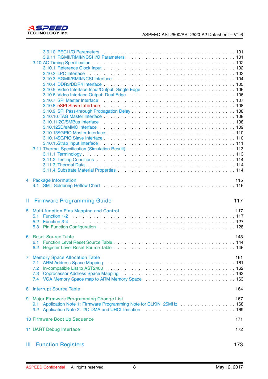
ASPEED AST2500/AST2520 A2 Datasheet – V1.6 3.9.10 PECI I/O Parameters . . . . . . . . . . . . . . . . . . . . . . . . . . . . . . . . . . . . . . 101 3.9.11 RGMII/RMII/NCSI I/O Parameters . . . . . . . . . . . . . . . . . . . . . . . . . . . . . . . 101 3.10 AC Timing Specification . . . . . . . . . . . . . . . . . . . . . . . . . . . . . . . . . . . . . . . . . 102 3.10.1 Reference Clock Input . . . . . . . . . . . . . . . . . . . . . . . . . . . . . . . . . . . . . . 102 3.10.2 LPC Interface . . . . . . . . . . . . . . . . . . . . . . . . . . . . . . . . . . . . . . . . . . . 103 3.10.3 RGMII/RMII/NCSI Interface . . . . . . . . . . . . . . . . . . . . . . . . . . . . . . . . . . . 104 3.10.4 DDR3/DDR4 Interface . . . . . . . . . . . . . . . . . . . . . . . . . . . . . . . . . . . . . . 105 3.10.5 Video Interface Input/Output: Single Edge . . . . . . . . . . . . . . . . . . . . . . . . . . . 106 3.10.6 Video Interface Output: Dual Edge . . . . . . . . . . . . . . . . . . . . . . . . . . . . . . . 106 3.10.7 SPI Master Interface . . . . . . . . . . . . . . . . . . . . . . . . . . . . . . . . . . . . . . 107 3.10.8 eSPI Slave Interface . . . . . . . . . . . . . . . . . . . . . . . . . . . . . . . . . . . . . . 108 3.10.9 SPI Pass-through Propagation Delay . . . . . . . . . . . . . . . . . . . . . . . . . . . . . . 108 3.10.10JTAG Master Interface . . . . . . . . . . . . . . . . . . . . . . . . . . . . . . . . . . . . . . 108 3.10.11I2C/SMBus Interface . . . . . . . . . . . . . . . . . . . . . . . . . . . . . . . . . . . . . . 108 3.10.12SD/eMMC Interface . . . . . . . . . . . . . . . . . . . . . . . . . . . . . . . . . . . . . . . 109 3.10.13SGPIO Master Interface . . . . . . . . . . . . . . . . . . . . . . . . . . . . . . . . . . . . . 110 3.10.14SGPIO Slave Interface . . . . . . . . . . . . . . . . . . . . . . . . . . . . . . . . . . . . . . 110 3.10.15Strap Input Interface . . . . . . . . . . . . . . . . . . . . . . . . . . . . . . . . . . . . . . . 111 . . . . . . . . . . . . . . . . . . . . . . . . . . . . . . . 113 3.11.1 Terminology . . . . . . . . . . . . . . . . . . . . . . . . . . . . . . . . . . . . . . . . . . . . 113 3.11.2 Testing Conditions . . . . . . . . . . . . . . . . . . . . . . . . . . . . . . . . . . . . . . . . 114 3.11.3 Thermal Data . . . . . . . . . . . . . . . . . . . . . . . . . . . . . . . . . . . . . . . . . . . 114 3.11.4 Substrate Material Properties . . . . . . . . . . . . . . . . . . . . . . . . . . . . . . . . . . 114 3.11 Thermal Specification (Simulation Result) 4 Package Information 4.1 SMT Soldering Reflow Chart 115 . . . . . . . . . . . . . . . . . . . . . . . . . . . . . . . . . . . . . . 116 II Firmware Programming Guide 117 5 Multi-function Pins Mapping and Control 117 5.1 Function 1-2 . . . . . . . . . . . . . . . . . . . . . . . . . . . . . . . . . . . . . . . . . . . . . . . 117 5.2 Function 3-4 . . . . . . . . . . . . . . . . . . . . . . . . . . . . . . . . . . . . . . . . . . . . . . . 127 5.3 Pin Function Configuration . . . . . . . . . . . . . . . . . . . . . . . . . . . . . . . . . . . . . . . 128 6 Reset Source Table 143 6.1 Function Level Reset Source Table . . . . . . . . . . . . . . . . . . . . . . . . . . . . . . . . . . . 144 6.2 Register Level Reset Source Table . . . . . . . . . . . . . . . . . . . . . . . . . . . . . . . . . . . 146 7 Memory Space Allocation Table 161 7.1 ARM Address Space Mapping . . . . . . . . . . . . . . . . . . . . . . . . . . . . . . . . . . . . . 161 7.2 In-compatible List to AST2400 . . . . . . . . . . . . . . . . . . . . . . . . . . . . . . . . . . . . . 162 7.3 Coprocessor Address Space Mapping . . . . . . . . . . . . . . . . . . . . . . . . . . . . . . . . . 163 7.4 VGA Memory Space map to ARM Memory Space . . . . . . . . . . . . . . . . . . . . . . . . . . 163 8 Interrupt Source Table 164 9 Major Firmware Programming Change List 167 9.1 Application Note 1: Firmware Programming Note for CLKIN=25MHz . . . . . . . . . . . . . . . . 168 9.2 Application Note 2: I2C DMA and UHCI limitation . . . . . . . . . . . . . . . . . . . . . . . . . . . 169 10 Firmware Boot Up Sequence 11 UART Debug Interface III Function Registers 171 172 173 ASPEED Confidential All rights reserved. 8 May 12, 2017
分享到:
收藏