�
分类号——
UI)C
武汉理j亡大学硕一卜学位论文
密
级
学校代码
10497
劣j凄理歹大
学 位 论
浮文
题 目
堑墅丝鲎壁丛鑫线鲍笪甚盈塞墨遮盐
多苣文:旦b曼Si堡坠!垒鱼Q壁垒望垂旦曼墨ig望Q£B曼曼!垒坠g坠!垒!
题 目
丛i坌互Q墨!£ip里垒!璺h!!迅!曼堕塾垒
研究生姓名
奎
整
指导教师姓名至盎然——一职称—j些坠一学位—_主睦
单位名称盛婆垄墨苤堂垄鲎瞳邮编箜QQZQ
姓名越垩塞
职称 副垫撞
学位谴±
副指导教师单位名称峦垫垄三基鲎堡堂瞳
单位名称盛垫垄三基鲎堡堂瞳
邮编
邮编 430070
申请学位级别
殛±
学科专业名称整鍪蠢堑堡
论文提交El期2Q!兰生垒旦论文答辩日期2Q!羔生三月:
学位授予单位盛婆垄墨盘堂学位授予日期
答辩委员会主席主:l蓝亟. 评阅人赳蓝迅
鲰元
2010年11月
一一……
独创性声明
f嬲煳掣必
本人声明,所呈交的论文是本人在导师指导下进行的研究工作及
取得的研究成果。尽我所知,除了文中特别加以标注和致谢的地方外,
论文中不包含其他人已经发表或撰写过的研究成果,也不包含为获得
武汉理工大学或其他教育机构的学位或证书而使用过的材料。与我一
同工作的同志对本研究所做的任何贡献均已在论文中作了明确的说
明并表示了谢意。签名:碰日期:翌!丛多/I
学位论文使用授权书
本人完全了解武汉理工大学有关保留、使用学位论文的规定,即
学校有权保留并向国家有关部门或机构送交论文的复印件和电子版,
允许论文被查阅和借阅。本人授权武汉理工大学可以将本学位论文的
全部内容编入有关数据库进行检索,可以采用影印、缩印或其他复制
手段保存或汇编本学位论文。同时授权经武汉理工大学认可的国家有
关机构或论文数据库使用或收录本学位论文,并向社会公众提供信息
服务。
(保密的论文在解密后应遵守此规定)
研究生(签名):名身色 导师(签名):舐衫舌期功ffl口r、弓1
(注:此页内容装订在论文扉页
�
武汉理工大学硕士学位论文
摘 要
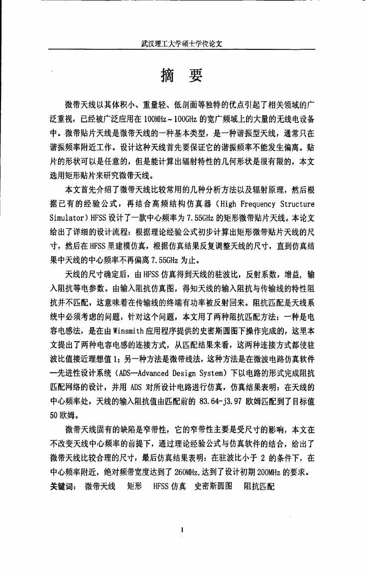
微带天线以其体积小、重量轻、低剖面等独特的优点引起了相关领域的广
泛重视,已经被广泛应用在IOOMHz—IOOGHz的宽广频域上的大量的无线电设备
中。微带贴片天线是微带天线的一种基本类型,是一种谐振型天线,通常只在
谐振频率附近工作。设计这种天线首先要保证它的谐振频率不能发生偏离。贴
片的形状可以是任意的,但是能计算出辐射特性的几何形状是很有限的,本文
选用矩形贴片来研究微带天线。
本文首先介绍了微带天线比较常用的几种分析方法以及辐射原理,然后根
据已有的经验公式,再结合高频结构仿真器(High Frequency Structure
Simulator)HFSS设计了一款中心频率为7.55GHz的矩形微带贴片天线。本论文
给出了详细的设计流程:根据理论经验公式初步计算出矩形微带贴片天线的尺
寸,然后在HFSS里建模仿真,根据仿真结果反复调整天线的尺寸,直到仿真结
果中天线的中心频率不再偏离7.55GHz为止。
天线的尺寸确定后,由HFSS仿真得到天线的驻波比,反射系数,增益,输
入阻抗等电参数。由输入阻抗仿真图,得知天线的输入阻抗与传输线的特性阻
抗并不匹配,这意味着在传输线的终端有功率被反射回来。阻抗匹配是天线系
统中必须考虑的问题,针对这个问题,本文用了两种阻抗匹配方法:一种是电
容电感法,是在由Winsmith应用程序提供的史密斯圆图下操作完成的,这里本
文提出了两种电容电感的连接方式,从匹配结果来看,这两种连接方式都使驻
波比值接近理想值1;另一种方法是微带线法,这种方法是在微波电路仿真软件
一先进性设计系统(ADS—Advanced Design System)下以电路的形式完成阻抗
匹配网络的设计,并用ADS对所设计电路进行仿真,仿真结果表明:在天线的
中心频率处,天线的输入阻抗值由匹配前的83.64一j3.97欧姆匹配到了目标值
50欧姆。
微带天线固有的缺陷是窄带性,它的窄带性主要是受尺寸的影响,本文在
不改变天线中心频率的前提下,通过理论经验公式与仿真软件的结合,给出了
微带天线比较合理的尺寸,最后仿真结果表明:在驻波比小于2的条件下,在
中心频率附近,绝对频带宽度达到了260MHz,达到了设计初期200MHz的要求。
关键词: 微带天线 矩形HFSS仿真史密斯圆图 阻抗匹配
�
Abstract
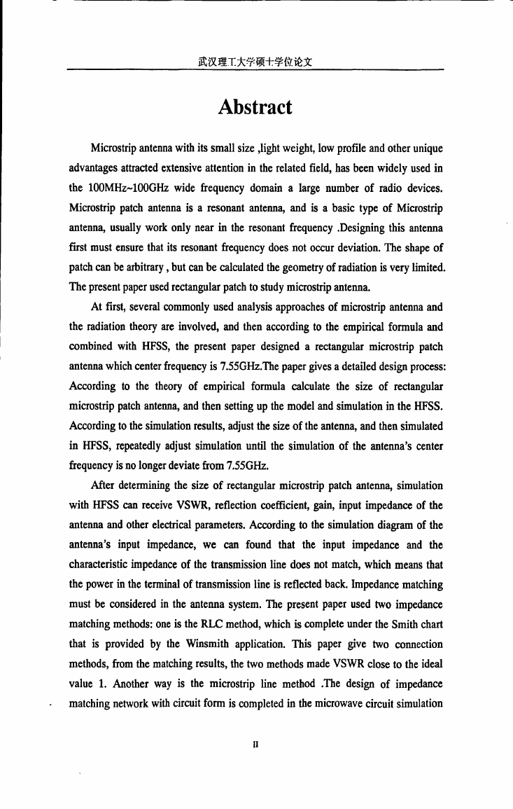
Microstrip antenna with its small size,light weight,low profile and other unique
advantages attracted extensive attention jn the related field,has been widely used in
the 100MHz一100GHz wide frequency domain a large number of radio devices.
Microstrip patch antenna is a resonant antenna,and is a basic type of Microstrip
antenna,usually work only near in the resonant frequency.Designing this antenna
first must ensure that its resonant frequency does not occur deviation.The shape of
patch can be arbitrary,bm Call be calculated the geometry of radiation is very limited.
The present P叩er used rectangular patch tO study microstrip antenna.
At first,several commonly used analysis approaches of microstrip antenna and
the radiation theory are involved,and then according to the empirical formula and
combined with HFSS,the present paper designed a rectangular microstrip patch
antenna which center frequency is 7.55GHz.The paper gives a detailed design process:
According to the theory of empirical formula calculate the size of rectangular
microstrip patch antenna,and then setting up the model and simulation in the HFSS.
According to the simulation results,adjust the size of the antenna,and then simulated
in HFSS,repeatedly adjust simulation until the simulation of the antenna,s center
frequency is no longer deviate from 7.55GHz.
After determining the size of rectangular microstrip patch antenna,simulation
with HFSS call receive VSWR,reflection coefficient,gain,input impedance of thc
antenna and other electrical parameters.According to the simulation diagram of the
antenna's input impedance,we can found that the input impedance and the
characteristic impedance of the transmission line does not match,which means that
the power in the terminal of transmission line is reflected back.Impedance matching
must be considered in the antenna system.The present paper used two impedance
matching methods:one is the RLC method,which is complete under the Smith ch砌
that is provided by the Winsmith application.This paper give two connection
methods,from the matching results,the two methods made VSWR close to the ideal
value 1.Another way is the microstrip line method.The design of impedance
matching network with circuit form is completed in the microwave circuit simulation
Il
�
武汉理工大学硕十学位论文
softwave--Advanced Design System(ADS),and the designed circuit is simulated by
ADS.The simulation results show that the input impedance value iS matched from
83.64-j3.97 ohms to a target value of 50 ohms at the antenna’S center frequency.
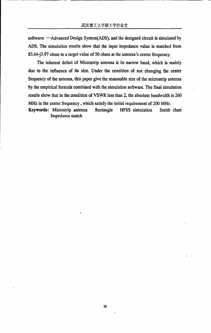
ne inherent defect of Microstrip antenna is its narrow band,which is mainly
duo to the influence of its size.Under the condition of not changing the center
frequency of the antenna,this paper give the reasonable size of the microstrip antenna
by the empirical formula combined with the simulation software.The final simulation
results show that in the condition of VSWR less than 2,the absolute bandwidth is 260
MHz in the center frequency,which satisfy the initial requirement of 200 MHz.
Keywords:Microstrip antenna
HFSS simulation
Rectangle
Smith chart
Impedance match
III
�
武汉理工大学硕士学位论文
目录
摘 要……………………………………………………………………………………………………………………………..1
Abstract………………………………………………………………………………………………………………………….】[I
目录……………………………………………………………………………………………………………………………….1
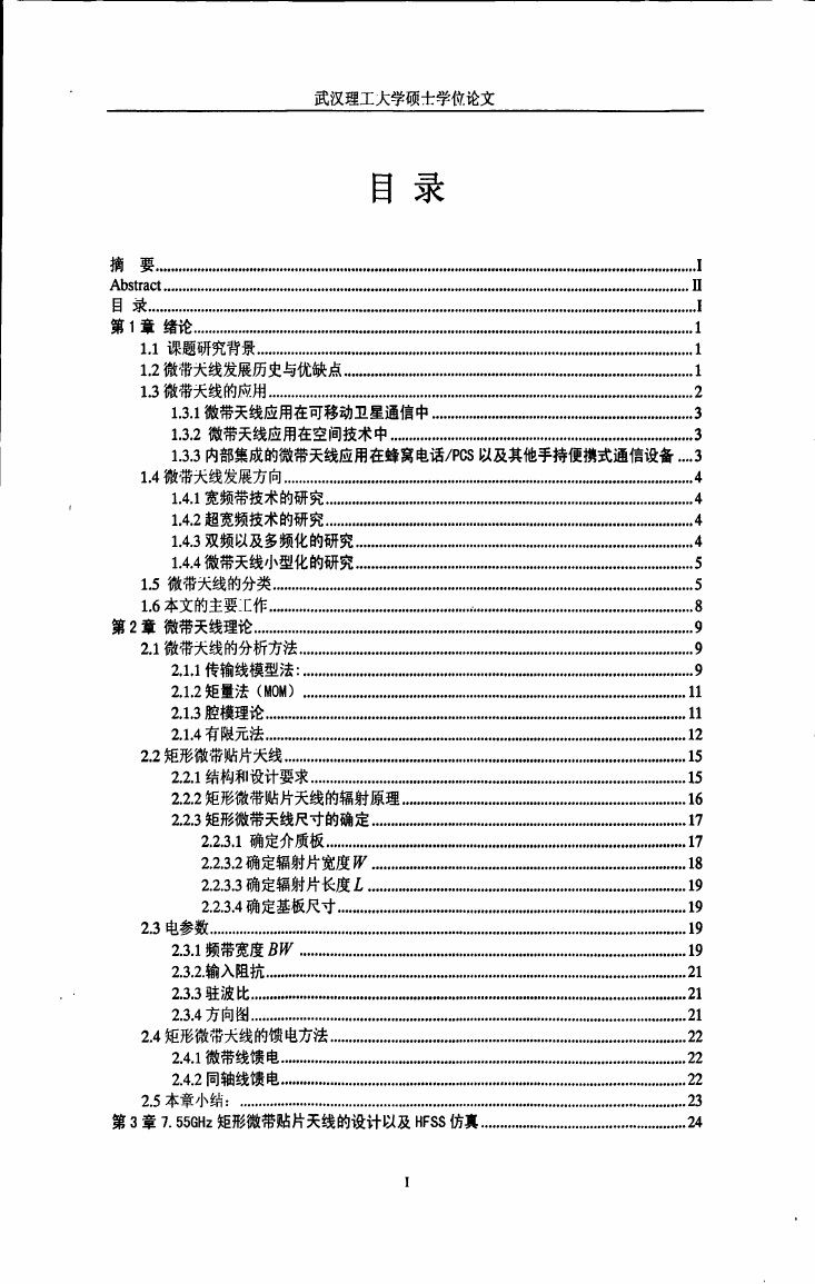
第1章绪论……………………………………………………………………………………….1
1.1课题研究背景…………………………………………………………………………….1
1.2微带天线发展历史与优缺点……………………………………………………………1
1.3微带天线的应用……………………………………………………………………………2
1.3.1微带天线应用在可移动卫星通信中………………………………………………3
1.3.2微带天线应用在空间技术中……………………………………………………3
1.3.3内部集成的微带天线应用在蜂窝电话/PCS以及其他手持便携式通信设备…3
1.4微带天线发展方向………………………………………………………………………。4
1.4.1宽频带技术的研究………………………………………………………………。4
1.4.2超宽频技术的研究………………………………………………………………。4
1.4.3双频以及多频化的研究………………………………………………………….4
1.4.4微带天线小型化的研究…………………………………………………………..5
1.5微带天线的分类…………………………………………………………………………5
1.6本文的主要:[作…………………………………...………………………………………8
第2章微带天线理论………………………………………………………………………………9
2.1微带天线的分析方法……………………………………………………………………..9
2.1.1传输线模型法:……………………………………………………………………。9
2.1.2矩量法(MOM)………………………………………………………………………………………。11
2.1.3腔模理论………………………………………………………………………….11
2.1.4有I;艮元法…………………………………………………………………………………………………12
2.2矩形微带贴片天线……………………………………………………………………….15
2.2.1结构和设计要求………………………………………………………………….15
2.2.2矩形微带贴片天线的辐射原理…………………………………………………16
2.2.3矩形微带天线尺寸的确定………………………………………………………17
2.2.3.1确定介质板………………………………………………………………..17
2.2.3.2确定辐射片宽度形………………………………………………………18
2.2.3.3确定辐射片长度£……………………………...…………………………。19
2.2.3.4确定基板尺寸…………………………………………………………….19
2.3电参数……………………………………………………………………………………19
2.3.1频带宽度B形………………………………………...…………………………19
2.3.2.输入阻抗………………………………………………………………………….21
2.3.3驻波比…………………………………………………………………………………………………….2l
2.3.4方向图…………………………………………………………………………………………………….21
2.4矩形微带天线的馈电方法………………………………………………………………。22
2.4.1微带线馈电……………………………………………………………………….22
2.4.2同轴线馈电……………………………………………………………………….22
2.5本章小结:………………………………………………………………………………23
第3章7.55GHz矩形微带贴片天线的设计以及HFSS仿真……………………………………24
�
武汉理_r大学硕士学位论文
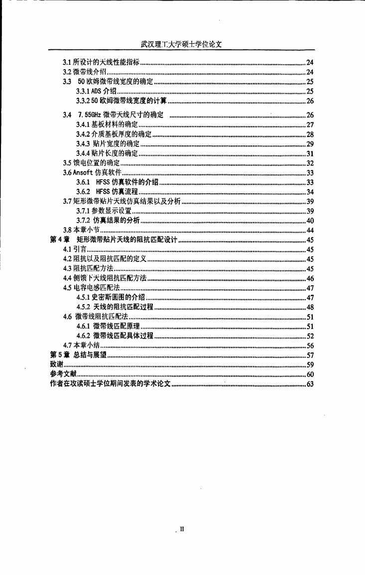
3.1所设计的天线性能指标…………………………………………………………………24
3.2微带线介钌{……………………………………………………………………………….24
50欧姆微带线宽度的确定…………………………………………………………..25
3.3
3.3.1 ADS介绍………………………………………………………………………………………………….21;
3.3.2 50欧姆微带线宽度的计算………………………………………………………26
3.4
3.6.1
3.6.2
7.55GHz微带天线尺寸的确定………………………………………..…………….26
3.4.1基板材料的确定……………………………………………………………………27
3.4.2介质基板厚度的确定…………………………………………………………….28
3.4.3贴片宽度的确定……………………………………………………………......…29
3.4.4贴片长度的确定………………………………………………………………….31
3.5馈电位置的确定…………………………………………………………………………32
3.6 Ansoft仿真软件……………………………………………………………………….33
HFSS仿真软件的介绍……………………………………………………………33
HFSS仿真流程………………………………………...……………………...….34
3.7矩形微带贴片天线仿真结果以及分析…………………………………………………39
3.7.1参数显示设置……………………………………………………………………。39
3.7.2仿真结果的分析…………………………………………………………………40
3.8本章小节……………………………………………………………………………………44
第4章矩形微带贴片天线的阻抗匹配设计………………………………………………….45
4.1·;I言………………………………………………………………………………………………………………….45
4.2阻抗以及阻抗匹配的定义……………………………………………………………...…45
4.3阻抗匹配方法…………………………………………………………………………….45
4.4侧馈下天线阻抗匹配方法……………………………………………………………..46
4.5电容电感匹配法…………………………………………………………………………47
4.5.1史密斯圆图的介绍…………………………………………………………………47
4.5.2天线的阻抗匹配过程……………………………………………...…………….48
4.6微带线阻抗匹酉己法………………………………………………………………………51
4.6.1微带线匹配原理…………………………………………………………………….51
4.6.2微带线匹配具体过程……………………………………………………………52
4.7本章小结…………………………………………………………………………………56
第5章总结与展望………………………………………………………………………………..57
致谢………………………………………………………………………………………………………………………………!;9
参考文献………………………………………………………………………………………...…..60
作者在攻读硕士学位期间发表的学术论文…………………….:…………………………...……63
�





 2023年江西萍乡中考道德与法治真题及答案.doc
 2012年重庆南川中考生物真题及答案.doc
 2013年江西师范大学地理学综合及文艺理论基础考研真题.doc
 2020年四川甘孜小升初语文真题及答案I卷.doc
 2020年注册岩土工程师专业基础考试真题及答案.doc
 2023-2024学年福建省厦门市九年级上学期数学月考试题及答案.doc
 2021-2022学年辽宁省沈阳市大东区九年级上学期语文期末试题及答案.doc
 2022-2023学年北京东城区初三第一学期物理期末试卷及答案.doc
 2018上半年江西教师资格初中地理学科知识与教学能力真题及答案.doc
 2012年河北国家公务员申论考试真题及答案-省级.doc
 2020-2021学年江苏省扬州市江都区邵樊片九年级上学期数学第一次质量检测试题及答案.doc
 2022下半年黑龙江教师资格证中学综合素质真题及答案.doc