logo资料库

nCode2018版帮助文件.pdf

第1页 / 共422页
第2页 / 共422页
第3页 / 共422页
第4页 / 共422页
第5页 / 共422页
第6页 / 共422页
第7页 / 共422页
第8页 / 共422页
资料共422页,剩余部分请下载后查看
About this Manual
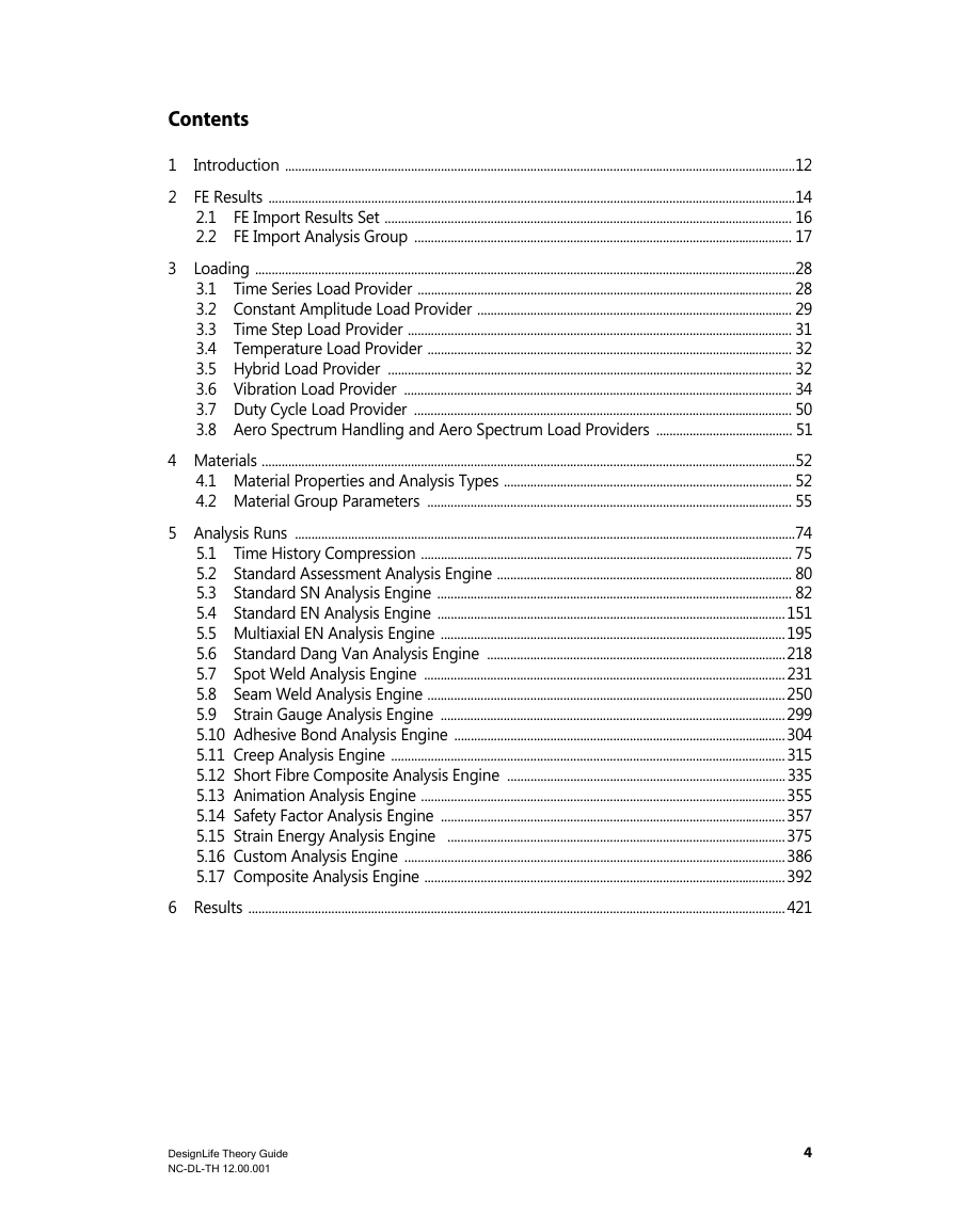
Contents
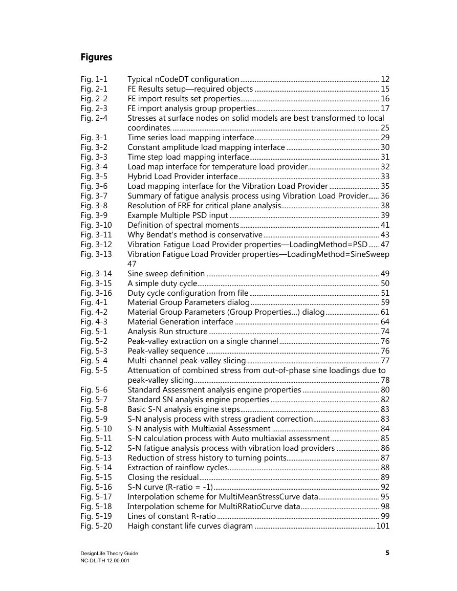
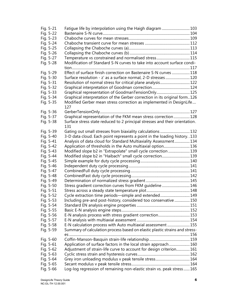
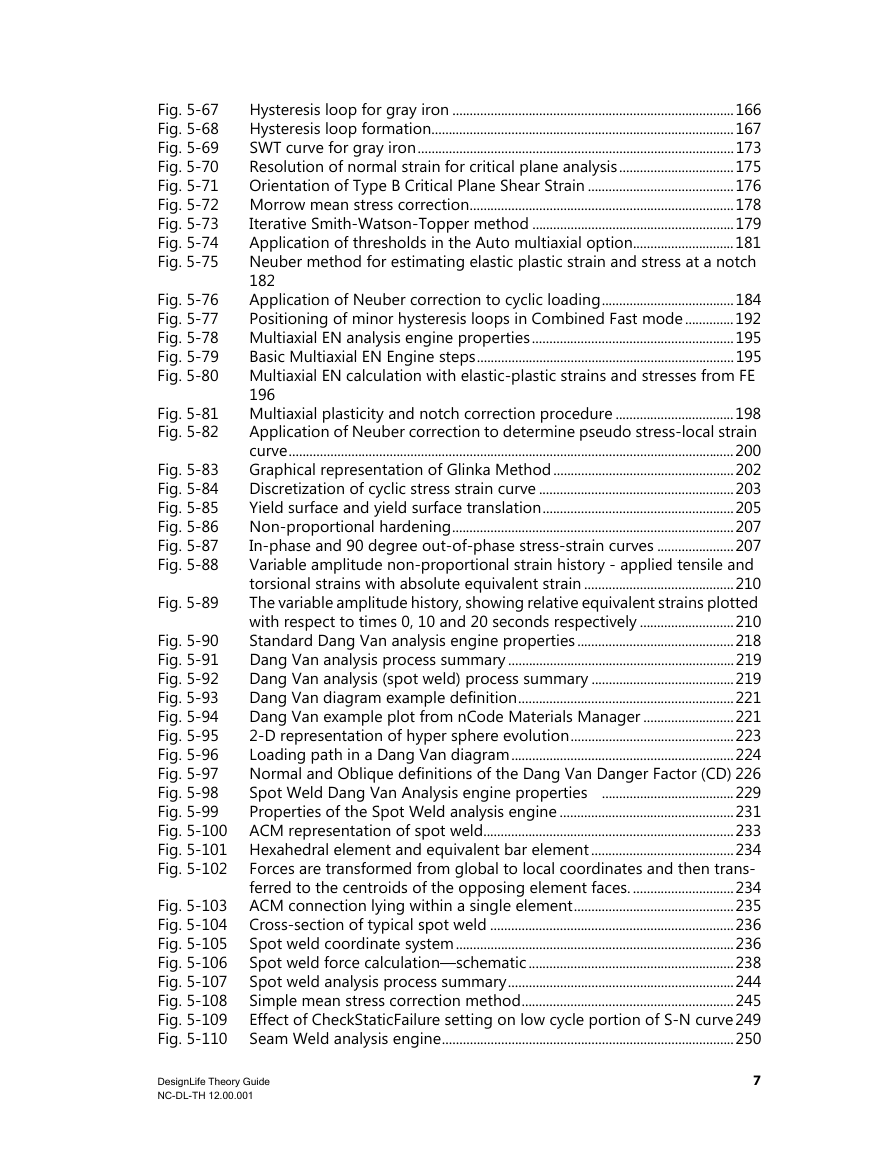
Figures
Tables
1 Introduction
2 FE Results
2.1 FE Import Results Set
2.2 FE Import Analysis Group
2.2.1 SelectionGroupType
2.2.2 MaterialAssignmentGroup
2.2.3 IgnoreZeroData
2.2.4 SolutionLocation
Element
NodeOnElement
AveragedNodeOnElement
SpotWeld
SeamWeld
StrainGauge
AdhesiveBond
2.2.5 EntityDataType
Stress
LinearStrain
ForceMoment
Displacement
Vibration
StressAndStrain
2.2.6 SurfaceNodesOnly
2.2.7 ResolveToLocal
2.2.8 Stress Gradients
2.2.9 ShellLayer
2.2.10 MaterialOrientationTensor
2.2.11 StateVariableKey
2.2.12 IncludeSpotWeldNuggets
3 Loading
3.1 Time Series Load Provider
3.2 Constant Amplitude Load Provider
3.3 Time Step Load Provider
3.4 Temperature Load Provider
3.5 Hybrid Load Provider
3.6 Vibration Load Provider
3.6.1 Resolution of FRF to Abs Max, Signed Von Mises, or Critical Plane
3.6.2 Combination of Load PSD and FRF to Get Local PSD (PSD Cycle Counter)
3.6.3 Multiple Random Inputs (Multi-PSD Analysis)
References
3.6.4 PSD-rainflow Prediction Using Lalanne, Dirlik, Narrow Band, Steinberg (PSD Cycle Counter)
Lalanne
Dirlik
Narrow Band
Steinberg
3.6.5 Sine-on-random-rainflow Prediction (Sine-on-random Cycle Counter)
3.6.6 Combination of SineDwell Definition with FRF to Get Local Rainflow Count
3.6.7 Combination of Swept-sine Definition with FRF to Get Local Rainflow Count
3.6.8 Superposition of Static Load Case
3.6.9 Inclusion of a Temperature Load Case
3.6.10 Vibration Load Provider properties
FrequencySelectionMethod
MinFrequency
MaxFrequency
FrequencyInterval
InterpolationMethod
CycleCountBins
LoadingMethod
PSDCycleCountMethod
ExposureDuration
NoiseFloor
SweepType
SweepRate
NumberOfSweeps
3.7 Duty Cycle Load Provider
3.8 Aero Spectrum Handling and Aero Spectrum Load Providers
4 Materials
4.1 Material Properties and Analysis Types
4.2 Material Group Parameters
4.2.1 Scale Factor and Offset
4.2.2 Surface Finish and Surface Treatment Settings
KTreatment
KUser
KRoughness
Enter Roughness Factor
Enter Surface Roughness
Descriptive
4.2.3 Weld Diameter
Enter Value
Automatic
4.2.4 Default Temperature
4.2.5 ShapeFactor
4.2.6 Adhesive Thickness
4.2.7 Bond Line Offset
4.2.8 Initial Crack Size
4.2.9 Material Generation
Standard SN Property Generation
Standard EN Property Generation
Dang Van Property Generation
5 Analysis Runs
5.1 Time History Compression
5.2 Standard Assessment Analysis Engine
5.3 Standard SN Analysis Engine
5.3.1 Summary
5.3.2 Note on Rainflow Cycle Counting
5.3.3 Note on Damage Calculation and Accumulation
5.3.4 SNMethod
Standard
MultiMeanCurve
MultiRRatioCurve
Haigh
Bastenaire
MultiTemperatureCurve
Chaboche
Chaboche Transient
Using Chaboche mean stress correction
Custom
5.3.5 Note on Application of Surface Correction Factors
Standard
Bastenaire
Multi-curve Options
5.3.6 CombinationMethod
AbsMaxPrincipal
SignedVonMises
SignedShear
CriticalPlane
MaxPrincipal
VonMises
Shear
MaxPrincipal
VonMises
Shear
5.3.7 MeanStressCorrection
None
Goodman
GoodmanTensionOnly
Gerber
GerberTensionOnly
Interpolate
FKM
Chaboche
5.3.8 InterpolationLimit
5.3.9 MultiaxialAssessment
MultiAxialAssessment = None
MultiAxialAssessment = SimpleBiaxiality
MultiAxialAssessment = Standard
MultiAxialAssessment = Auto
Note on Duty Cycle Processing
5.3.10 Certainty of Survival
5.3.11 ScaleFactor
5.3.12 OutputMaxMin
5.3.13 BackCalcMode
5.3.14 TargetDamage
5.3.15 BackCalcAccuracy
5.3.16 BackCalcMaxScale
5.3.17 SmallCycleCorrection
5.3.18 EventProcessing
Independent
CombinedFull
CombinedFast
5.3.19 OutputEventResults
5.3.20 CheckStaticFailure
5.3.21 DamageFloor
5.3.22 MaxDamage
5.3.23 StaticFailureDamage
5.3.24 StressGradients
5.3.25 StressGradientsUser
5.3.26 Extracting Temperatures Cycle by Cycle
5.4 Standard EN Analysis Engine
5.4.1 Summary - Standard EN steps
5.4.2 Summary - Multiaxial Assessment steps
Auto mode
5.4.3 Note on Stresses and Strains
5.4.4 Standard Strain-life Material Properties
Strain-life Relationship
Stress-strain Relationship
5.4.5 Gray Iron Strain-life Material Properties
5.4.6 Gray Iron Material Behavior
5.4.7 Note on Rainflow Cycle Counting for Strain-life Calculations
5.4.8 ENMethod
Standard
MultiMeanCurve
MultiRRatioCurve
MultiTemperatureCurve
5.4.9 Gray Iron
5.4.10 CombinationMethod
AbsMaxPrincipal
SignedVonMises
SignedShear
CriticalPlane
TypeBCriticalPlaneShearStrain
5.4.11 MeanStressCorrection
None
Morrow
SmithWatsonTopper
Interpolate
5.4.12 InterpolationLimit
5.4.13 MultiAxialAssessment
Auto mode
Note on Duty Cycle Processing
5.4.14 ElasticPlasticCorrection
None
Neuber
Hoffmann-Seeger
5.4.15 PlasticLimitLoadCorrection
5.4.16 CertaintyOfSurvival
5.4.17 ScaleFactor
5.4.18 OutputMaxMin
5.4.19 BackCalcMode
5.4.20 TargetDamage
5.4.21 BackCalcAccuracy
5.4.22 BackCalcMaxScale
5.4.23 EventProcessing
5.4.24 OutputEventResults
5.4.25 SWTMethod
5.4.26 DamageCalcMethod
5.4.27 LookUpTableSize
5.4.28 CheckStaticFailure
5.4.29 DamageFloor
5.4.30 MaxDamage
5.4.31 StaticFailureDamage
5.4.32 StressGradients
5.4.33 StressGradientsUser
5.5 Multiaxial EN Analysis Engine
5.5.1 Summary
5.5.2 Material Properties
5.5.3 Multiaxial Plasticity and Notch Correction
Basic Principles
Notch Corrections
Plasticity Model
Flow Rule
Plastic Modulus Function
Hardening Rule
5.5.4 Wang-Brown Method
5.5.5 Multiaxial Rainflow Counting Method
Damage Model
5.5.6 Analysis Engine Properties
DamageMethod
PlasticityModel
NotchCorrection
CertaintyOfSurvival
ScaleFactor
EventProcessing
OutputEventResults
DamageFloor
MaxDamage
TimeHistoryProcessing
CheckMaxStrain
StrainLimitDamage
NumberOfSurfaces
MaxStrain
YieldStrain
IncrementMethod
IncrementSize
ExternalIncrementSize
InternalIncrementSize
Beee
Chi
HardeningTolerance
KPrimeRatio
nPrimeRatio
5.6 Standard Dang Van Analysis Engine
5.6.1 Summary
5.6.2 Dang Van Material parameters
5.6.3 The Dang Van criterion
5.6.4 Sheet Cut Edge Effect
5.6.5 Outputs of a Dang Van analysis
Safety Factor
TauCritical
PhCritical
CriticalClearance
FreeEdge
TauZero
DangerFactor
5.6.6 Properties of the Dang Van analysis engine
HardeningParameter
OutputSafetyFactor
OutputTauCritical
OutputPhCritical
OutputTauZero
OutputDangerFactor
OutputCriticalClearance
OutputFreeEdge
DangerFactorType
EventProcessing
OutputEventResults
MaxSafetyFactor
EquivalentStrainLoadcaseIndex
StrainHardeningEffect
NumberOfAngles
ProcessMiddleSheets
OutputSheetCount
OutputSpotWeldDiameter
OutputSpotWeldNumber
StressGradients
StressGradientsUser
5.7 Spot Weld Analysis Engine
5.7.1 Background
Introduction and Modeling Guidelines
Force and Moment Recovery
Stress Calculations
Material Data
Material Data - Coefficient values used in MDB databases
Analysis Process Summary
5.7.2 CombinationMethod and SNMethod
5.7.3 MeanStressCorrection
None
Simple
FKM
5.7.4 NumberOfAngles
5.7.5 ProcessMiddleSheets
5.7.6 CertaintyOfSurvival
5.7.7 ScaleFactor
5.7.8 CalculateTorsion
5.7.9 Output...
5.7.10 BackCalcMode
5.7.11 Target Damage
5.7.12 BackCalcAccuracy
5.7.13 BackCalcMaxScale
EventProcessing
5.7.14 CheckStaticFailure
5.7.15 DamageFloor
5.7.16 MaxDamage
5.7.17 StaticFailureDamage
5.8 Seam Weld Analysis Engine
5.8.1 Introduction
5.8.2 Grouping and Weld Types
Fillet
Overlap
Laser Overlap
Laser Edge Overlap
Solid Weld
Generic
5.8.3 Modeling Guidelines and Calculation Points
General Guidelines
Fillet
Overlap and Laser Edge Overlap Welds
Laser Overlap Welds
5.8.4 Calculation Points and Stress Recovery
Fillet Welds
Overlap Welds
Laser Overlap Welds
Laser Edge Overlap
Generic
5.8.5 Calculation of Stresses from Grid Point Forces and Moments
Additional Notes
5.8.6 Calculation of Stresses from Nodal Displacements and Rotations
Additional Notes
5.8.7 Calculation of Stresses from Solid Elements
5.8.8 Calculation Method
Stress Calculation and Combination
Abs Max Principal Method
Critical Plane Method
Weld Normal Method
Determine the Degree of Bending
Material Properties and Interpolation
Thickness Correction
Fatigue Calculation
Note on Differences in Calculations for Different Weld Types
5.8.9 CombinationMethod
5.8.10 MeanStressCorrection
5.8.11 MultiaxialAssessment
None
SimpleBiaxiality
Standard
5.8.12 CertaintyOfSurvival
5.8.13 ScaleFactor
5.8.14 ThicknessCorrection
5.8.15 BackCalcMode
5.8.16 EventProcessing
Independent
CombinedFull
CombinedFast
5.8.17 OutputEventResults
True
False
5.8.18 CheckStaticFailure
5.8.19 Damage Floor
5.8.20 MaxDamage
5.8.21 StaticFailureDamage
5.9 Strain Gauge Analysis Engine
5.9.1 Standard - Prerequisites
5.9.2 StrainGaugePositioning - Prerequisites
5.9.3 Properties and Functions of the Strain Gauge Analysis Engine
Properties for the Standard method
Properties for the StrainGaugePositioning method
5.9.4 Strain Gauge Positioning Background
5.9.5 References
5.10 Adhesive Bond Analysis Engine
5.10.1 Introduction
5.10.2 Modeling Guidelines, Grouping and Required FE Results
5.10.3 Calculation Points and FE Results Translation
5.10.4 Material Properties
5.10.5 Calculation Method
ScaleFactor
OutputSafetyFactor
OutputEventResults
5.11 Creep Analysis Engine
5.11.1 Summary
5.11.2 Creep—Background
CreepMethod
5.11.3 The Larson-Miller Method
5.11.4 The Chaboche Method
5.11.5 CombinationMethod
MaxPrincipal
VonMises
Shear
AbsMaxPrincipal
SignedVonMises
SignedShear
5.11.6 Stress Limits
5.11.7 Temperature Limits
5.11.8 Duty Cycles
OutputEventResults
StaticFailureDamage
TemperatureSelection
ScaleFactor
5.12 Short Fibre Composite Analysis Engine
5.12.1 Introduction
5.12.2 Engine Operation Summary
5.12.3 Fibre Share Calculation
5.12.4 Material Properties and Local SN Curve Determination
Calculation from Basquin Curves
SN Curves from Digimat
Haigh Curves from Digimat
5.12.5 Analysis Engine Properties
CombinationMethod
SN Method
MeanStressCorrection
MultiaxialAssessment
CertaintyOfSurvival
ScaleFactor
OutputMaxMin
OutputMaterialNames
EventProcessing
OutputEventResults
CheckStaticFailure
DamageFloor
MaxDamage
StaticFailureDamage
5.12.6 Note on Results
5.13 Animation Analysis Engine
5.13.1 Introduction
5.13.2 Analysis Engine Properties
Filename
Overwrite
Decimation
MaxFramesToOutput
5.14 Safety Factor Analysis Engine
5.14.1 Summary
5.14.2 Properties of Safety Factor Analysis Engine
Safety Factor Method
Combination Method
InterpolationLimit
Mean Stress Correction
CertaintyOfSurvival
ScaleFactor
OutputMaxMin
OutputMaterialNames
OutputDangerFactor
TargetLife
MaxSafetyFactor
FactorOFSafetyType
MaxPrincipalPlaneStress
EventProcessing
OutputEventResults
CheckStaticFailure
StressGradients
StressGradientsUser
5.14.3 Details of Safety Factor Analysis Methods
Constant R-ratio factor of safety
Goodman
Goodman tension only
Gerber
Gerber tension only
FKM
Haigh Constant Life Curve
5.14.4 Outputs of a Safety Factor Analysis
Safety factor
Danger Factor
Maximum/Minimum Stress
Plane Angle Phi and Plane Angle Theta
5.15 Strain Energy Analysis Engine
5.15.1 Introduction
5.15.2 Engine Operation Summary
5.15.3 Rainflow Cycle Counting in Strain Energy Analysis
5.15.4 Properties
WNMethod
CombinationMethod
MeanStressCorrection
MultiaxialAssessment
CertaintyOfSurvival
ScaleFactor
OutputMaxMin
OutputMaterialNames
EventProcessing
OutputEventResults
CheckStaticFailure
DamageFloor
MaxDamage
StaticFailureDamage
5.16 Custom Analysis Engine
5.16.1 Introduction
5.16.2 Engine Operation Summary
5.16.3 Material Properties
5.16.4 Properties
5.16.5 General Properties
MultiaxialAssessment
ScaleFactor
OutputMaxMin
OutputMaterialNames
5.16.6 Duty Cycle Properties
EventProcessing
OutputEventResults
5.16.7 Fatigue Properties
CombinationMethod
None
Custom
CycleCounter
Method
DamageFloor
MaxDamage
CheckStaticFailure
StaticFailureDamage
5.16.8 Custom Properties
CustomCombinationOutputs
CustomCombinationTracked
5.17 Composite Analysis Engine
5.17.1 Engine Operation Summary
5.17.2 Material properties
5.17.3 Analysis Engine Properties
MultiaxialAssessment
ScaleFactor
OutputMaxMin
OutputMaterialNames
EventProcessing
OutputEventResults
FailureCriteriaSource
StaticDesignParameter
OutputSeparateFailures
Failure Envelope
Single Failure Criteria
Conservative Failure Criteria
5.17.4 Strength Assessment
Overview
Engineering design parameters
Maximum stress criterion
Maximum strain criterion
Franklin-Marin criterion (1968)
Hoffman criterion (1967)
Norris criterion (1962)
Tsai-Hill criterion (1948)
Tsai-Wu criterion (1971)
Christensen criterion (1997)
Hashin criterion (1980)
Hashin-Rotem criterion (1973)
Applicability of intra-laminar failure criteria
References
6 Results

DesignLife Theory Guide DesignLife Theory Guide NC-DL-TH 12.00.001 1
About this Manual Copyright Notice All of this documentation, and the software it describes, are copyrighted with all rights reserved. Under copyright laws, neither the documentation or the software may be copied, photocopied, reproduced in any way, translated, or converted into any machine-readable form or any electronic medium, in whole or in part, without express written permission from HBM United Kingdom Limited (HBM). Failure to obtain such permission may result in prosecu- tion. The software suite that comprises nCode 12.0 (including GlyphWorks®, Automation, VibeSys, and DesignLife™) and their component programs and files are the property of HBM. Please refer to the About screen in the software and the About folder in the nCode 12.0 instal- lation and in the docs\licenses folder in nCode Automation installation for details on third party software used and respective licenses and/or copyright notices. nCode 12.0 is protected under copyright law and is licensed for use only by a user who has obtained the necessary license, or in the case of a multi-user license may only be used by up to the maximum number of users specified in the license agreement. The sale, lease, hire rental, or any other reassignment of the product to, or by, a third party without the prior writ- ten consent of HBM is expressly forbidden. © 2016 HBM United Kingdom Limited. All worldwide rights reserved. GlyphWorks® is a registered trademark of HBM. All other trademarks are the property of their respective owners. Warranty Notice While HBM makes the product as reliable as is reasonably possible, HBM does not warrant that the product will function properly under all hardware platforms or software environ- ments. Certain combinations of third party software and/or manufacturers modifications to hardware and software may impact upon the operation of HBM software. HBM has tested the software and reviewed the documentation but HBM makes no warranty, implicit or explicit, with respect to the product, its quality, performance, merchantability, or fit- ness for a specific usage. This software and documentation are licensed “as is” and you—the licensee—assume the entire risk as to their quality and performance when you use the prod- uct. Liability Notice HBM will not be liable for damages arising from the results, direct or indirect, special, inciden- tal, or consequential, of the licensee's usage or misusage of the product, even if advised of the possibility of such damages. In particular, and without prejudice to the foregoing, HBM has no liability for any programs or data stored or used with HBM software, including the costs of recovering such programs or data. Feedback We value your feedback. If you have any documentation questions, comments, or concerns, please e-mail us at:
techdocs@hbmncode.com Customer Support For issues involving the installation or use of your software, please e-mail us at: support@hbmncode.com or use the nCode website, www.hbm.com/ncode, to find support information for your coun- try.
Contents 1 Introduction ..........................................................................................................................................................12 2 FE Results ...............................................................................................................................................................14 2.1 FE Import Results Set ........................................................................................................................... 16 2.2 FE Import Analysis Group .................................................................................................................. 17 3 Loading ...................................................................................................................................................................28 3.1 Time Series Load Provider ................................................................................................................. 28 3.2 Constant Amplitude Load Provider ............................................................................................... 29 3.3 Time Step Load Provider .................................................................................................................... 31 3.4 Temperature Load Provider .............................................................................................................. 32 3.5 Hybrid Load Provider .......................................................................................................................... 32 3.6 Vibration Load Provider ..................................................................................................................... 34 3.7 Duty Cycle Load Provider .................................................................................................................. 50 3.8 Aero Spectrum Handling and Aero Spectrum Load Providers ......................................... 51 4 Materials .................................................................................................................................................................52 4.1 Material Properties and Analysis Types ....................................................................................... 52 4.2 Material Group Parameters .............................................................................................................. 55 5 Analysis Runs .......................................................................................................................................................74 5.1 Time History Compression ................................................................................................................ 75 5.2 Standard Assessment Analysis Engine ......................................................................................... 80 5.3 Standard SN Analysis Engine ........................................................................................................... 82 5.4 Standard EN Analysis Engine .........................................................................................................151 5.5 Multiaxial EN Analysis Engine ........................................................................................................195 5.6 Standard Dang Van Analysis Engine ..........................................................................................218 5.7 Spot Weld Analysis Engine .............................................................................................................231 5.8 Seam Weld Analysis Engine ............................................................................................................250 5.9 Strain Gauge Analysis Engine ........................................................................................................299 5.10 Adhesive Bond Analysis Engine ....................................................................................................304 5.11 Creep Analysis Engine .......................................................................................................................315 5.12 Short Fibre Composite Analysis Engine ....................................................................................335 5.13 Animation Analysis Engine ..............................................................................................................355 5.14 Safety Factor Analysis Engine ........................................................................................................357 5.15 Strain Energy Analysis Engine ......................................................................................................375 5.16 Custom Analysis Engine ...................................................................................................................386 5.17 Composite Analysis Engine .............................................................................................................392 6 Results ..................................................................................................................................................................421 DesignLife Theory Guide NC-DL-TH 12.00.001 4
Figures Fig. 1-1 Fig. 2-1 Fig. 2-2 Fig. 2-3 Fig. 2-4 Fig. 3-1 Fig. 3-2 Fig. 3-3 Fig. 3-4 Fig. 3-5 Fig. 3-6 Fig. 3-7 Fig. 3-8 Fig. 3-9 Fig. 3-10 Fig. 3-11 Fig. 3-12 Fig. 3-13 Fig. 3-14 Fig. 3-15 Fig. 3-16 Fig. 4-1 Fig. 4-2 Fig. 4-3 Fig. 5-1 Fig. 5-2 Fig. 5-3 Fig. 5-4 Fig. 5-5 Fig. 5-6 Fig. 5-7 Fig. 5-8 Fig. 5-9 Fig. 5-10 Fig. 5-11 Fig. 5-12 Fig. 5-13 Fig. 5-14 Fig. 5-15 Fig. 5-16 Fig. 5-17 Fig. 5-18 Fig. 5-19 Fig. 5-20 Typical nCodeDT configuration.............................................................................. 12 FE Results setup—required objects ...................................................................... 15 FE import results set properties.............................................................................. 16 FE import analysis group properties..................................................................... 17 Stresses at surface nodes on solid models are best transformed to local coordinates..................................................................................................................... 25 Time series load mapping interface...................................................................... 29 Constant amplitude load mapping interface .................................................... 30 Time step load mapping interface......................................................................... 31 Load map interface for temperature load provider........................................ 32 Hybrid Load Provider interface............................................................................... 33 Load mapping interface for the Vibration Load Provider ............................ 35 Summary of fatigue analysis process using Vibration Load Provider...... 36 Resolution of FRF for critical plane analysis....................................................... 38 Example Multiple PSD input .................................................................................... 39 Definition of spectral moments.............................................................................. 41 Why Bendat's method is conservative................................................................. 43 Vibration Fatigue Load Provider properties—LoadingMethod=PSD...... 47 Vibration Fatigue Load Provider properties—LoadingMethod=SineSweep 47 Sine sweep definition ................................................................................................. 49 A simple duty cycle...................................................................................................... 50 Duty cycle configuration from file......................................................................... 51 Material Group Parameters dialog........................................................................ 59 Material Group Parameters (Group Properties…) dialog.............................. 61 Material Generation interface ................................................................................. 64 Analysis Run structure................................................................................................ 74 Peak-valley extraction on a single channel........................................................ 76 Peak-valley sequence ................................................................................................. 76 Multi-channel peak-valley slicing .......................................................................... 77 Attenuation of combined stress from out-of-phase sine loadings due to peak-valley slicing........................................................................................................ 78 Standard Assessment analysis engine properties ........................................... 80 Standard SN analysis engine properties ............................................................. 82 Basic S-N analysis engine steps.............................................................................. 83 S-N analysis process with stress gradient correction..................................... 83 S-N analysis with Multiaxial Assessment ............................................................ 84 S-N calculation process with Auto multiaxial assessment ........................... 85 S-N fatigue analysis process with vibration load providers ........................ 86 Reduction of stress history to turning points.................................................... 87 Extraction of rainflow cycles..................................................................................... 88 Closing the residual..................................................................................................... 89 S-N curve (R-ratio = -1)............................................................................................. 92 Interpolation scheme for MultiMeanStressCurve data.................................. 95 Interpolation scheme for MultiRRatioCurve data............................................ 98 Lines of constant R-ratio ........................................................................................... 99 Haigh constant life curves diagram ....................................................................101 DesignLife Theory Guide NC-DL-TH 12.00.001 5
Fig. 5-21 Fig. 5-22 Fig. 5-23 Fig. 5-24 Fig. 5-25 Fig. 5-26 Fig. 5-27 Fig. 5-28 Fig. 5-29 Fig. 5-30 Fig. 5-31 Fig. 5-32 Fig. 5-33 Fig. 5-34 Fig. 5-35 Fig. 5-36 Fig. 5-37 Fig. 5-38 Fig. 5-39 Fig. 5-40 Fig. 5-41 Fig. 5-42 Fig. 5-43 Fig. 5-44 Fig. 5-45 Fig. 5-46 Fig. 5-47 Fig. 5-48 Fig. 5-49 Fig. 5-50 Fig. 5-51 Fig. 5-52 Fig. 5-53 Fig. 5-54 Fig. 5-55 Fig. 5-56 Fig. 5-57 Fig. 5-58 Fig. 5-59 Fig. 5-60 Fig. 5-61 Fig. 5-62 Fig. 5-63 Fig. 5-64 Fig. 5-65 Fig. 5-66 Fatigue life by interpolation using the Haigh diagram ...............................103 Bastenaire S-N curve.................................................................................................104 Chaboche curves for mean stresses....................................................................109 Chaboche transient curve for mean stresses ..................................................112 Collapsing the Chaboche curves (a)....................................................................113 Collapsing the Chaboche curves (b) ...................................................................114 Temperature vs constrained and normalised stress.....................................115 Modification of Standard S-N curves to take into account surface condi- tion...................................................................................................................................117 Effect of surface finish correction on Bastenaire S-N curves ....................118 Surface resolution - z’ as a surface normal, 2-D stresses ...........................120 Resolution of normal stress for critical plane analysis.................................122 Graphical interpretation of Goodman correction..........................................124 Graphical representation of GoodmanTensionOnly.....................................125 Graphical interpretation of the Gerber correction in its original form..126 Modified Gerber mean stress correction as implemented in DesignLife.... 127 GerberTensionOnly....................................................................................................127 Graphical representation of the FKM mean stress correction..................128 Surface stress state reduced to 2 principal stresses and their orientation. 131 Gating out small stresses from biaxiality calculations .................................132 3-D data cloud. Each point represents a point in the loading history. .133 Analysis of data cloud for Standard Multiaxiality Assessment.................134 Application of thresholds in the Auto multiaxial option.............................136 Modified slope b2 in "Extrapolate" small cycle correction ........................139 Modified slope b2 in "Haibach" small cycle correction...............................139 Simple example for duty cycle processing.......................................................140 Independent duty cycle processing....................................................................141 CombinedFull duty cycle processing..................................................................141 CombinedFast duty cycle processing.................................................................142 Determination of normalized stress gradient .................................................145 Stress gradient correction curves from FKM guideline ...............................146 Stress across a steady state temperature plot................................................148 Cycle extraction time periods—simple and extended.................................149 Including pre-and post-history, considered too conservative .................150 Standard EN analysis engine properties ...........................................................151 Basic E-N analysis engine steps............................................................................152 E-N analysis process with stress gradient correction...................................153 E-N analysis with multiaxial assessment ...........................................................154 E-N calculation process with Auto multiaxial assessment .........................155 Summary of calculation process based on elastic plastic strains and stress- es ......................................................................................................................................156 Coffin-Manson-Basquin strain-life relationship.............................................159 Application of surface factors in the local strain approach .......................160 Adjustment of strain-life curve to account for design criterion...............161 Cyclic stress strain and hysteresis curves..........................................................162 Grey iron unloading modulus v peak tensile stress......................................164 Secant modulus v peak tensile stress.................................................................164 Log-log regression of remaining non-elastic strain vs. peak stress.......165 DesignLife Theory Guide NC-DL-TH 12.00.001 6
Fig. 5-81 Fig. 5-82 Fig. 5-83 Fig. 5-84 Fig. 5-85 Fig. 5-86 Fig. 5-87 Fig. 5-88 Fig. 5-89 Fig. 5-76 Fig. 5-77 Fig. 5-78 Fig. 5-79 Fig. 5-80 Fig. 5-67 Fig. 5-68 Fig. 5-69 Fig. 5-70 Fig. 5-71 Fig. 5-72 Fig. 5-73 Fig. 5-74 Fig. 5-75 Hysteresis loop for gray iron .................................................................................166 Hysteresis loop formation.......................................................................................167 SWT curve for gray iron...........................................................................................173 Resolution of normal strain for critical plane analysis.................................175 Orientation of Type B Critical Plane Shear Strain ..........................................176 Morrow mean stress correction............................................................................178 Iterative Smith-Watson-Topper method ..........................................................179 Application of thresholds in the Auto multiaxial option.............................181 Neuber method for estimating elastic plastic strain and stress at a notch 182 Application of Neuber correction to cyclic loading......................................184 Positioning of minor hysteresis loops in Combined Fast mode..............192 Multiaxial EN analysis engine properties..........................................................195 Basic Multiaxial EN Engine steps..........................................................................195 Multiaxial EN calculation with elastic-plastic strains and stresses from FE 196 Multiaxial plasticity and notch correction procedure ..................................198 Application of Neuber correction to determine pseudo stress-local strain curve................................................................................................................................200 Graphical representation of Glinka Method....................................................202 Discretization of cyclic stress strain curve ........................................................203 Yield surface and yield surface translation.......................................................205 Non-proportional hardening.................................................................................207 In-phase and 90 degree out-of-phase stress-strain curves ......................207 Variable amplitude non-proportional strain history - applied tensile and torsional strains with absolute equivalent strain ...........................................210 The variable amplitude history, showing relative equivalent strains plotted with respect to times 0, 10 and 20 seconds respectively ...........................210 Standard Dang Van analysis engine properties.............................................218 Fig. 5-90 Dang Van analysis process summary .................................................................219 Fig. 5-91 Dang Van analysis (spot weld) process summary .........................................219 Fig. 5-92 Dang Van diagram example definition..............................................................221 Fig. 5-93 Dang Van example plot from nCode Materials Manager ..........................221 Fig. 5-94 2-D representation of hyper sphere evolution...............................................223 Fig. 5-95 Loading path in a Dang Van diagram................................................................224 Fig. 5-96 Normal and Oblique definitions of the Dang Van Danger Factor (CD) 226 Fig. 5-97 Spot Weld Dang Van Analysis engine properties ......................................229 Fig. 5-98 Properties of the Spot Weld analysis engine ..................................................231 Fig. 5-99 Fig. 5-100 ACM representation of spot weld........................................................................233 Fig. 5-101 Hexahedral element and equivalent bar element .........................................234 Forces are transformed from global to local coordinates and then trans- Fig. 5-102 ferred to the centroids of the opposing element faces. .............................234 ACM connection lying within a single element..............................................235 Cross-section of typical spot weld ......................................................................236 Spot weld coordinate system................................................................................236 Spot weld force calculation—schematic ...........................................................238 Spot weld analysis process summary.................................................................244 Simple mean stress correction method.............................................................245 Effect of CheckStaticFailure setting on low cycle portion of S-N curve249 Seam Weld analysis engine....................................................................................250 Fig. 5-103 Fig. 5-104 Fig. 5-105 Fig. 5-106 Fig. 5-107 Fig. 5-108 Fig. 5-109 Fig. 5-110 DesignLife Theory Guide NC-DL-TH 12.00.001 7
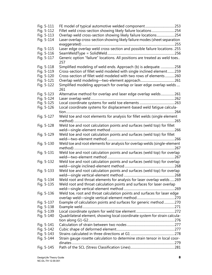
FE model of typical automotive welded component...................................253 Fig. 5-111 Fig. 5-112 Fillet weld cross-section showing likely failure locations ...........................254 Fig. 5-113 Overlap weld cross-section showing likely failure locations.....................254 Laser overlap cross-section showing likely failure modes (sheet separation Fig. 5-114 exaggerated)................................................................................................................255 Laser edge overlap weld cross-section and possible failure locations .255 Fig. 5-115 Fig. 5-116 SeamWeldType = SolidWeld.................................................................................256 Fig. 5-117 Generic option “failure” locations. All positions are treated as weld toes.. 257 Simplified modeling of weld ends. Approach (b) is adequate. ................258 Fig. 5-118 Cross-section of fillet weld modeled with single inclined element........259 Fig. 5-119 Fig. 5-120 Cross-section of fillet weld modeled with two rows of elements ...........260 Fig. 5-121 Overlap weld modeling—two-element approach.........................................261 Simplified modeling approach for overlap or laser edge overlap welds .... Fig. 5-122 261 Alternative method for overlap and laser edge overlap welds................261 Laser overlap weld .....................................................................................................262 Local coordinate systems for weld toe elements ..........................................263 Local coordinate systems for displacement-based weld fatigue calcula- tion...................................................................................................................................264 Fig. 5-127 Weld toe and root elements for analysis for fillet welds (single element method) .........................................................................................................................265 Fig. 5-123 Fig. 5-124 Fig. 5-125 Fig. 5-126 Fig. 5-128 Weld toe and root calculation points and surfaces (weld top) for fillet weld—single-element method .............................................................................266 Fig. 5-129 Weld toe and root calculation points and surfaces (weld top) for fillet weld—two-element method .................................................................................266 Fig. 5-130 Weld toe and root elements for analysis for overlap welds (single-element method) .........................................................................................................................267 Fig. 5-131 Weld toe and root calculation points and surfaces (weld top) for overlap weld—two-element method .................................................................................267 Fig. 5-132 Weld toe and root calculation points and surfaces (weld top) for overlap weld—single inclined-element method............................................................268 Fig. 5-133 Weld toe and root calculation points and surfaces (weld top) for overlap weld—single vertical-element method .............................................................268 Fig. 5-134 Weld root and throat elements for analysis for laser overlap welds .....269 Fig. 5-135 Weld root and throat calculation points and surfaces for laser overlap weld—single vertical-element method .............................................................269 Fig. 5-136 Weld toe, root and throat calculation points and surfaces for laser edge overlap weld—single vertical-element method.............................................270 Example of calculation points and surfaces for generic method ............270 Fig. 5-137 Example weld...............................................................................................................271 Fig. 5-138 Fig. 5-139 Local coordinate system for weld toe element ..............................................272 Fig. 5-140 Quadrilateral element, showing local coordinate system for strain calcula- tion along G1-G2........................................................................................................276 Calculation of strain between two nodes .........................................................277 Cubic shape of deformed element......................................................................277 Strains calculated in three directions at G1 .....................................................278 Strain gauge rosette calculation to determine strain tensor in local coor- dinates............................................................................................................................279 Path of the SCL (Stress Classification Lines).....................................................281 Fig. 5-141 Fig. 5-142 Fig. 5-143 Fig. 5-144 Fig. 5-145 DesignLife Theory Guide NC-DL-TH 12.00.001 8
分享到:
收藏