Cover
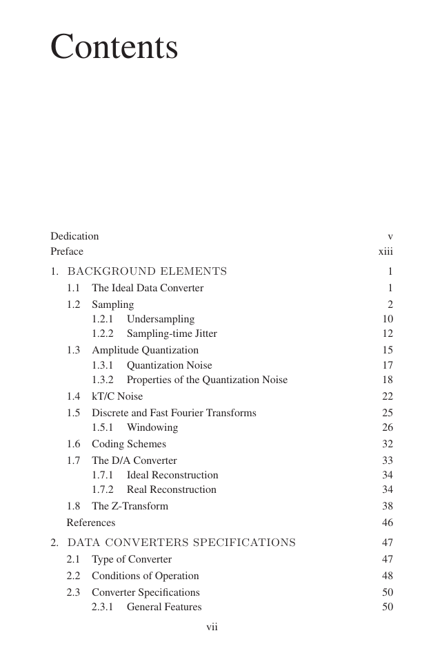
Contents
Preface
Chapter 1 BACKGROUNDELEMENTS
1.1 THE IDEAL DATA CONVERTER
1.2 SAMPLING
1.2.1 Undersampling
1.2.2 Sampling-time Jitter
1.3 AMPLITUDE QUANTIZATION
1.3.1 Quantization Noise
1.3.2 Properties of the Quantization Noise
1.4 kT/C NOISE
1.5 DISCRETE AND FAST FOURIER TRANSFORMS
1.5.1 Windowing
1.6 CODING SCHEMES
1.7 THE D/A CONVERTER
1.7.1 Ideal Reconstruction
1.7.2 Real Reconstruction
1.8 THE Z-TRANSFORM
PROBLEMS
REFERENCES
Chapter 2 DATACONVERTERSSPECIFICATIONS
2.1 TYPE OF CONVERTER
2.2 CONDITIONS OF OPERATION
2.3 CONVERTER SPECIFICATIONS
2.3.1 General Features
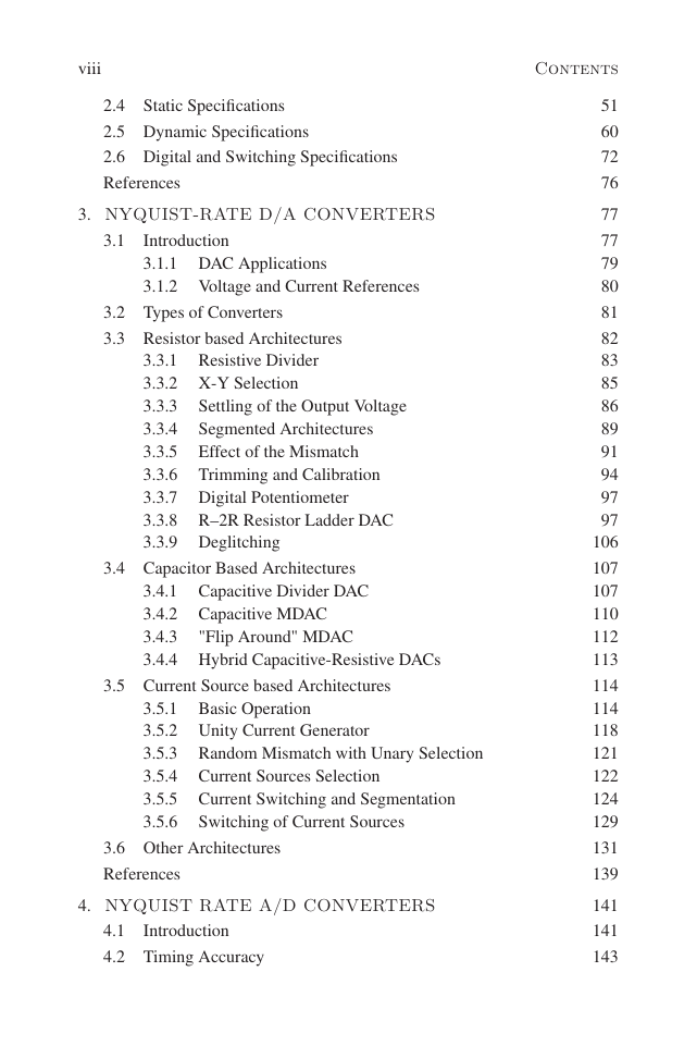
2.4 STATIC SPECIFICATIONS
2.5 DYNAMIC SPECIFICATIONS
2.6 DIGITAL AND SWITCHING SPECIFICATIONS
PROBLEMS
REFERENCES
Chapter 3 NYQUIST-RATEDIGITAL TO ANALOGCONVERTERS
3.1 INTRODUCTION
3.1.1 DAC Applications
3.1.2 Voltage and Current References
3.2 TYPES OF CONVERTERS
3.3 RESISTOR BASED ARCHITECTURES
3.3.1 Resistive Divide
3.3.2 X-Y Selection
3.3.3 Settling of the Output Voltage
3.3.4 Segmented Architectures
3.3.5 Effect of the Mismatch
3.3.6 Trimming and Calibration
3.3.7 Digital Potentiometer
3.3.8 R–2R Resistor Ladder DAC
3.3.9 Deglitching
3.4 CAPACITOR BASED ARCHITECTURES
3.4.1 Capacitive Divider DAC
3.4.2 Capacitive MDAC
3.4.3 "Flip Around" MDAC
3.4.4 Hybrid Capacitive-Resistive DACs
3.5 CURRENT SOURCE BASED ARCHITECTURES
3.5.1 Basic Operation
3.5.2 Unity Current Generator
3.5.3 Random Mismatch with Unary Selection
3.5.4 Current Sources Selection
3.5.5 Current Switching and Segmentation
3.5.6 Switching of Current Sources
3.6 OTHER ARCHITECTURES
PROBLEMS
REFERENCES
Chapter 4 NYQUIST RATEANALOG TO DIGITALCONVERTERS
4.1 INTRODUCTION
4.2 TIMING ACCURACY
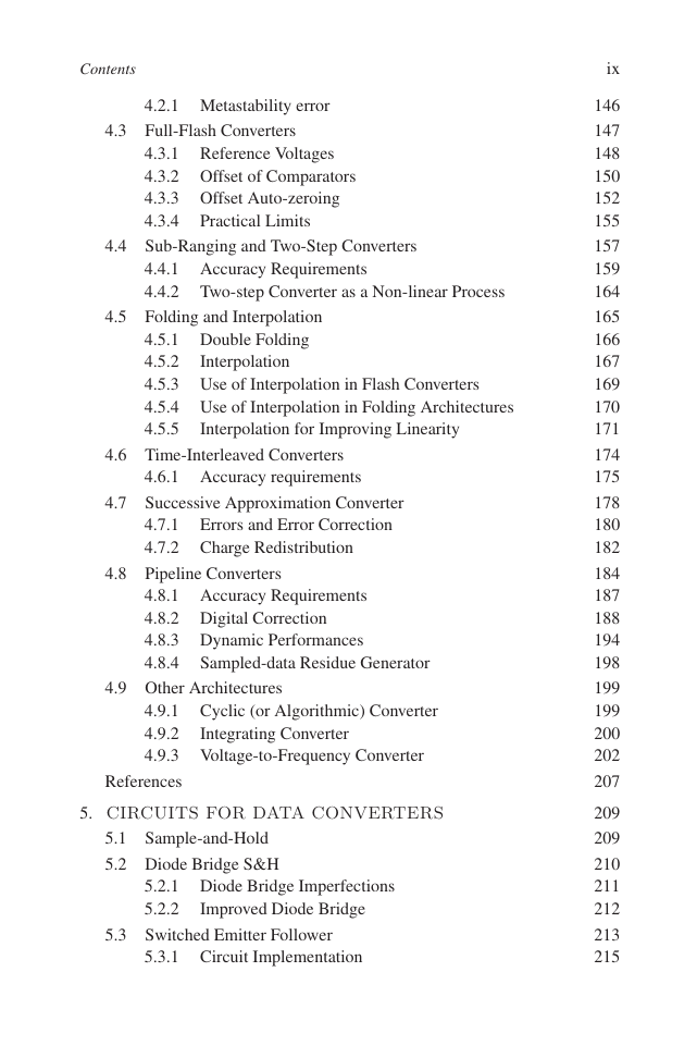
4.2.1 Metastability error
4.3 FULL-FLASH CONVERTERS
4.3.1 Reference Voltages
4.3.2 Offset of Comparators
4.3.3 Offset Auto-zeroing
4.3.4 Practical Limits
4.4 SUB-RANGING AND TWO-STEP CONVERTERS
4.4.1 Accuracy Requirements
4.4.2 Two-step Converter as a Non-linear Process
4.5 FOLDING AND INTERPOLATION
4.5.1 Double Folding
4.5.2 Interpolation
4.5.3 Use of Interpolation in Flash Converters
4.5.4 Use of Interpolation in Folding Architectures
4.5.5 Interpolation for Improving Linearity
4.6 TIME-INTERLEAVED CONVERTERS
4.6.1 Accuracy requirements
4.7 SUCCESSIVE APPROXIMATION CONVERTER
4.7.1 Errors and Error Correction
4.7.2 Charge Redistribution
4.8 PIPELINE CONVERTERS
4.8.1 Accuracy Requirements
4.8.2 Digital Correction
4.8.3 Dynamic Performances
4.8.4 Sampled-data Residue Generator
4.9 OTHER ARCHITECTURES
4.9.1 Cyclic (or Algorithmic) Converter
4.9.2 Integrating Converter
4.9.3 Voltage-to-Frequency Converter
PROBLEMS
REFERENCES
Chapter 5 CIRCUITS FOR DATA CONVERTERS
5.1 SAMPLE-AND-HOLD
5.2 DIODE BRIDGE S&H
5.2.1 Diode Bridge Imperfections
5.2.2 Improved Diode Bridge
5.3 SWITCHED EMITTER FOLLOWER
5.3.1 Circuit Implementation
5.3.2 Complementary Bipolar S&H
5.4 FEATURES OF S&HS WITH BJT
5.5 CMOS SAMPLE-AND-HOLD
5.5.1 Clock Feed-through
5.5.2 Clock Feed-through Compensation
5.5.3 Two-stages OTA as T&H
5.5.4 Use of the Virtual Ground in CMOS S&H
5.5.5 Noise Analysis
5.6 CMOS SWITCH WITH LOW VOLTAGE SUPPLY
5.6.1 Switch Bootstrapping
5.7 FOLDING AMPLIFIERS
5.7.1 Current-Folding
5.7.2 Voltage Folding
5.8 VOLTAGE-TO-CURRENT CONVERTER
5.9 CLOCK GENERATION
PROBLEMS
REFERENCES
Chapter 6 OVERSAMPLINGAND LOW ORDERΣ∆ MODULATORS
6.1 INTRODUCTION
6.1.1 Delta and Sigma-Delta Modulation
6.2 NOISE SHAPING
6.3 FIRST ORDER MODULATOR
6.3.1 Intuitive Views
6.3.2 Use of 1-bit Quantization
6.4 SECOND ORDER MODULATOR
6.5 CIRCUIT DESIGN ISSUES
6.5.1 Offset
6.5.2 Finite Op-Amp Gain
6.5.3 Finite Op-Amp Bandwidth
6.5.4 Finite Op-Amp Slew-Rate
6.5.5 ADC Non-ideal Operatio
6.5.6 DAC Non-ideal Operation
6.6 ARCHITECTURAL DESIGN ISSUES
6.6.1 Integrator Dynamic Range
6.6.2 Dynamic Ranges Optimization
6.6.3 Sampled-data Circuit Implementation
6.6.4 Noise Analysis
6.6.5 Quantization Error and Dithering
6.6.6 Single-bit and Multi-bit
PROBLEMS
REFERENCES
Chapter 7 HIGH-ORDER, CTΣ∆ CONVERTERSAND Σ∆ DAC
7.1 SNR ENHANCEMENT
7.2 HIGH ORDER NOISE SHAPING
7.2.1 Single Stage Architectures
7.2.2 Stability Analysis
7.2.3 Weighted Feedback Summation
7.2.4 Modulator with Local Feedback
7.2.5 Chain of Integrators with Distributed Feedback
7.2.6 Cascaded Σ∆ Modulator
7.2.7 Dynamic range for MASH
7.3 CONTINUOUS-TIME Σ∆ MODULATORS
7.3.1 S&H Limitations
7.3.2 CT Implementations
7.3.3 Design of CT from Sampled-Data Equivalent
7.4 BAND-PASS Σ∆ MODULATOR
7.4.1 Interleaved N-Path Architecture
7.4.2 Synthesis of the NTF
7.5 OVERSAMPLING DAC
7.5.1 1-bit DAC
7.5.2 Double Return-to-zero DAC
PROBLEMS
REFERENCES
Chapter 8 DIGITALENHANCEMENTTECHNIQUES
8.1 INTRODUCTION
8.2 ERROR MEASUREMENT
8.3 TRIMMING OF ELEMENTS
8.4 FOREGROUND CALIBRATION
8.5 BACKGROUND CALIBRATION
8.5.1 Gain and Offset in Interleaved Converters
8.5.2 Offset Calibration without Redundancy
8.5.2.1 Gain Calibration in Interleaved Converters
8.6 DYNAMIC MATCHING
8.6.1 Butterfly Randomization
8.6.2 Individual Level Averaging
8.6.3 Data Weighted Averaging
8.7 DECIMATION AND INTERPOLATION
8.7.1 Decimation
8.7.2 Interpolation
PROBLEMS
REFERENCES
Chapter 9 TESTING OFD/A AND A/DCONVERTERS
9.1 INTRODUCTION
9.2 TEST BOARD
9.3 QUALITY AND RELIABILITY TEST
9.4 DATA PROCESSING
9.4.1 Best-fit-line
9.4.2 Sine Wave Fitting
9.4.3 Histogram Method
9.5 STATIC DAC TESTING
9.5.1 Transfer Curve Test
9.5.2 Superposition of Errors
9.5.3 Non-linearity Errors
9.6 DYNAMIC DAC TESTING
9.6.1 Spectral Features
9.6.2 Conversion Time
9.6.3 Glitch Energy
9.7 STATIC ADC TESTING
9.7.1 Code Edge Measurement
9.8 DYNAMIC ADC TESTING
9.8.1 Time Domain Parameters
9.8.2 Improving the Spectral Purity of Sine Waves
9.8.3 Aperture Uncertainty Measure
9.8.4 Settling-time Measure
9.8.5 Use of FFT for Testing
PROBLEMS
REFERENCES



 2023年江西萍乡中考道德与法治真题及答案.doc
 2012年重庆南川中考生物真题及答案.doc
 2013年江西师范大学地理学综合及文艺理论基础考研真题.doc
 2020年四川甘孜小升初语文真题及答案I卷.doc
 2020年注册岩土工程师专业基础考试真题及答案.doc
 2023-2024学年福建省厦门市九年级上学期数学月考试题及答案.doc
 2021-2022学年辽宁省沈阳市大东区九年级上学期语文期末试题及答案.doc
 2022-2023学年北京东城区初三第一学期物理期末试卷及答案.doc
 2018上半年江西教师资格初中地理学科知识与教学能力真题及答案.doc
 2012年河北国家公务员申论考试真题及答案-省级.doc
 2020-2021学年江苏省扬州市江都区邵樊片九年级上学期数学第一次质量检测试题及答案.doc
 2022下半年黑龙江教师资格证中学综合素质真题及答案.doc