COMPUTER
ORGANIZATION
AND
ARCHITECTURE
Themes and Variations
ARM Processor
WORKBOOK
Alan Clements
�
Version 1
[WORKBOOK FOR COMPUTER ORGANIZATION AND ARCHITECTURE: THEME AND VARIATIONS]
INTRODUCTION
This workbook has been written to accompany Computer Organization and Architecture: Themes and Variations and is
designed to give students a practical introduction to the ARM processor simulator from Kiel. I have provided examples of the
use of the ARM family simulator plus notes and comments in order to allow students to work together in labs and tutorials, or
for individual study at home.
Before we introduce the simulator, we look at several background topics that are needed before you can begin to write
assembly-language level programs.
THE INSTRUCTION SET ARCHITECTURE
An instruction set architecture, or ISA, is an abstract model of a computer that describes what it does, rather than how it does
it. You could say that a computer’s instruction set architecture is its functional definition. Essentially, the ISA is concerned
with a computer’s internal storage (its registers), the operations that the computer can perform on data (the instruction set), and
the addressing modes used to access data. The term addressing mode is just a fancy way of expressing where the data is; for
example, you can say that the data is in location 100, or you can say that it’s 200 location from here, or you can say, “here’s the
actual data itself”.
The first part of Computer Organization and Architecture: Themes and Variations is concerned with the instruction set
architecture, and the second part is concerned with computer organization which described an ISA is actually implemented.
Today, the term microarchitecture has largely replaced the computer organization. In this workbook, we are interested in the
ISA, rather than the microarchitecture.
REGISTERS
A register is a storage device that holds a single data word exactly like a memory location. Registers are physically located on
the CPU chip and can be accessed far more rapidly than memory. You can think of a register as a place in which data is waiting
to be processed. When computers operate on data, they frequently operate on data that is in a register. For example, to perform
the multiplication A = B × C, you first read the values of B and C from memory into two registers. Then, you multiply the two
numbers in the registers and put the result in a register. Finally, the result is transferred from a register to location A in memory.
In principle, there’s no fundamental difference between a location in memory and a register. There are just a few registers in a
computer, but millions of storage locations in memory. Consequently, you need far fewer bits to specify a register than a
memory location. For example, if a computer has eight data registers, an instruction requires only three bits to select one of the
eight registers to be used by an operation; that is from 000 to 111. If you specify a memory location, you need 32 bits to select
one out of 232 possible locations (assuming a 32-bit address space).
The size of a register (its width in bits) is normally the same size as memory locations and the size of the arithmetic and logical
operations in the CPU. If you have a computer with 32-bit words, they are held in 32-bit memory locations and 32-bit registers
and are processed by 32-bit adders, and so on.
There is no fundamental difference between a register and a memory location. If you could store gigabytes of high-speed
memory on a CPU chip and you could use very long instruction words (i.e., with the long addresses needed to specify one
individual location) then there would be no point in using registers. If you had a computer with 4 Gbytes of memory (232 bytes)
and wished to have an instruction that could implement C = A + B (i.e., ADD C,A,B) the you would require typically 16 + 32
+ 32 + 32 = 112 bits (the 16 bits represent the number of bits to encode the actual operation and the three 32-bits are needed for
the addresses A, B, and C). No mainstream modern computer has such a long instruction word.
V 5.0
“© 2014 Cengage Learning. All Rights Reserved. May not be scanned, copied or duplicated, or posted to a publicly accessible website, in whole or in part
1 | P a g e
�
Version 1
[WORKBOOK FOR COMPUTER ORGANIZATION AND ARCHITECTURE: THEME AND VARIATIONS]
PROBLEM SET 1
1.
In your own words, explain what a register is in a computer.
2. How many registers does the 68K have?
3. How many registers does the ARM have?
4. What’s the processor with the largest number of registers that you can find?
5.
If a computer has 128 user-accessible general-purpose registers, how many bits are be required to access a register?
That is, how many bits does it take to specify 1 out of 128?
6. Suppose a computer has eight registers and a 24-bit instruction length. A data processing instruction is of the
ADD r1,r2,r3 which implements r1 = r2 + r3. How many bits in an instruction can be allocated to specifying an
operation if there are four general-purpose registers?
IMPORTANT POINT
Never confuse the following two concepts: value and address (or location). A memory location holds
a value which is the information stored in that location. The address of an item is where it is in
memory and its value is what it is.
For example, suppose memory location 1234 contains the value 55. If we add 1 to 55 we get 55 + 1
which is 56. That is, we’ve changed the value of a variable. Now, if we add 1 to the address 1234, we
get 1235. That’s a different location in memory which holds a different variable.
The reason for making this point is that it is all too easy to confuse these two concepts because of the
way we learn algebra at high school. We use equations like x = 4. When we write programs that use
variables, the variables usually refer to the locations of data not to the values. So, when we say x = 4,
we actually mean that the memory location called x contains the value 4.
PROBLEM SET 2
The following problems are intended to help you understand the history of the computer. These problems are intended as
discussion points and don’t have simple right or wrong answers. In order to do these questions you will need to read the Web-
based history material that accompanies this text. You will also need to use the web as a research tool.
1. When did the idea of a computer first occur to people?
2. What is a computer?
3. One of the names most associated with the history of computing is John von Neumann. Who was von Neumann? Did
he invent the computer?
4. When was the first microprocessor created – and by whom?
5. What was the form of the first memory used by computers (or computing devices)?
6. Who said (and when) “There is a world market for maybe five computers”.
7. What was the first hobby computer (personal computer) and when was it built?
8. Who was Konrad Zuse?
This warning symbol will appear
whenever a particularly
important or tricky concept is
introduced.
V 5.0
“© 2014 Cengage Learning. All Rights Reserved. May not be scanned, copied or duplicated, or posted to a publicly accessible website, in whole or in part
2 | P a g e
�
Version 1
[WORKBOOK FOR COMPUTER ORGANIZATION AND ARCHITECTURE: THEME AND VARIATIONS]
ADDRESSING MODES
An addressing mode is simply a means of expressing the location of an operand. An address can be a register such as r3, or
D7, or PC (program counter). An address can be a location in memory such as address 0x12345678. You can even express an
address indirectly by saying, for example, “the address is the location whose address is in register r1”. All the various ways of
expressing the location of data are called collectively addressing modes.
Suppose someone said, “Here’s ten dollars”. They are giving you the actual item. This is called a literal or immediate value
because it’s what you actually get. Unlike all other addressing modes, you don’t have to retrieve immediate data from a register
or memory location.
If someone says, “Go to room 30 and you’ll find the money on the table”, they are telling you where the money is (i.e., its
address is room 30). This is called an absolute address because expresses absolutely exactly where the money is. This
addressing modes is also called direct addressing.
Now here’s where the fun starts. Suppose someone says, “Go to room 40 and you’ll find something to your advantage on the
table”. You arrive at room 40 and see a message on the table saying, “The money is in room 60”. In this case we have an
indirect address because room 40 doesn’t give us with the money, but a pointer to where it is. We have to go to a second room
to get the money. Indirect addressing is also called pointer-based addressing, because you can think of the note in room 40 as
pointing to the actual data.
In real life we can’t confuse a room or address in with a sum of money. However, in a computer all data is stored in binary
form and the programmer has to remember whether a variable (or constant) is an address or a data value.
By the way, because there is no means of telling which operand is a source and which is a destination in a computer instruction
such as MOVE A,B and different computers use different conventions, I have decided to write the destination operand in bold
font to make it easier to understand the code. For example, MOVE A,B means that B is moved to A, because A is bold and
therefore the destination of the result.
Let’s look at three computer instructions in 68K assembly language. The operation MOVE D0,D1 means
copy the contents of register D0 into D1. The operation MOVE (A0),D1 means copy the contents of the
memory location pointed at by register A0 into register D1. This is an example of indirect addressing
because the instruction specifies register A0 as the source operand and then this value has to be read in
order to access the desired operand in memory.
Here we’ve used 68K instructions (the 68K instruction set is given as an appendix on page 8). In ARM
assembly language, which is the subject of this Workbook, indirect addressing is indicated by square brackets. For example,
LDR r0,[r1]indicates that the contents of the memory location pointed at by register r1 is to be read and copied into
register r0. Note that the ARM and 68K assembly languages specify the order of operands differently. In the assembly
language we use in this course:
Immediate (literal) addressing is indicated by a ‘#’ symbol in front of the operand (this convention is used by both the ARM
and 68K). Thus, #5 in an instruction means the actual value 5. A typical ARM instruction is MOV r0,#5 which means move
the value 5 into register r0.
Absolute (direct) addressing is not implemented by the ARM processor. It is provided by the 68K and Intel IA32 processors;
for example, the 68K instruction MOVE 1234,D0 means load register D0 with the contents of memory location 1234. The
ARM supports only register indirect addressing.
Indirect addressing is indicated by ARM processors by placing the pointer in square parentheses; for example, [r1]. All ARM
indirect addresses are of the basic form LDR r0,[r1] or STR r3,[r6]. There are variations on this addressing mode;
for example, LDR r0,[r1,#4]specifies an address that is four bytes on from the location pointed at by the contents of
register r1.
V 5.0
“© 2014 Cengage Learning. All Rights Reserved. May not be scanned, copied or duplicated, or posted to a publicly accessible website, in whole or in part
3 | P a g e
�
Version 1
[WORKBOOK FOR COMPUTER ORGANIZATION AND ARCHITECTURE: THEME AND VARIATIONS]
ADDRESSING MODES EXAMPLE
Let’s clarify addressing modes with a simple example. The memory map below gives the contents of each of the locations of a
simple 16-word memory. Each of these locations contains a 4-bit binary value. We are going to look at some examples of the
effect of computer operations. We adopt ARM-style assembly instructions and assume 4-bit addresses and 4-bit data.
Assume that r1 initially contains 0001 and r2 contains 1000
a. MOV r0,#1100
Register r0 is loaded with 1100
b. LDR r0,[r1]
Register r0 is loaded with 0011
c. LDR r0,[r2]
Register r0 is loaded with 1010
d. LDR r0,[r1,r2] Register indirect address (sum of r1 and r2) Register r0 is loaded with 1111
e. LDR r0,[r2,#4] Register indirect address (r2 + 4)
Register r0 is loaded with 0001
f. LDR r0,[r2,#-4] Register indirect address (r2 – 4)
Register r0 is loaded with 0000
Literal address
Register indirect address
Register indirect address
As you can see, the processor uses the address in r1 or r2 to access the appropriate memory location. ARM processors (like
other processors) are able to perform limited pointer arithmetic. For example, in (d) the effective address is given as [r1,r2],
which is the location pointed at by the sum of these two registers. The sum of r1 and r2 is 0001 + 1000 = 1001, so the contents
of location 1001 (i.e., 1111) are loaded into r0.
Example (e) calculates an effective address by adding 4 to the contents of r2 to get 1000 + 0100 = 1100. The contents of
memory location 1100 is 0001 and that value is loaded into r0. Note that example (f) is almost the same except that the
constant is negative. In this case the contents of location 1000 – 0100 = 0100 (i.e., 0000) are loaded into r0. A negative offset
like this accesses a location at a lower address.
V 5.0
“© 2014 Cengage Learning. All Rights Reserved. May not be scanned, copied or duplicated, or posted to a publicly accessible website, in whole or in part
4 | P a g e
00000010000100110010001000111010010000000101001001010001011100111000101010011111101010101011001111000001110110001110000011111010�
Version 1
[WORKBOOK FOR COMPUTER ORGANIZATION AND ARCHITECTURE: THEME AND VARIATIONS]
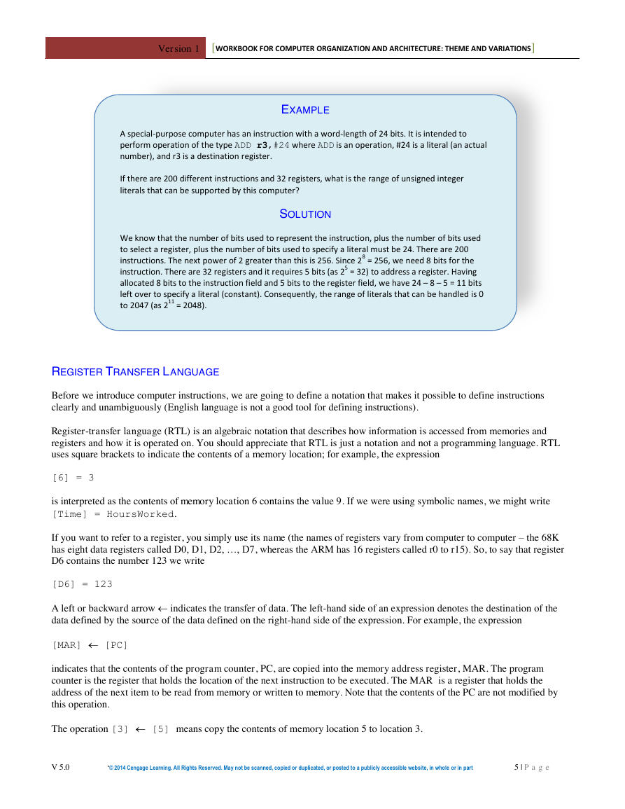
EXAMPLE
A special-purpose computer has an instruction with a word-length of 24 bits. It is intended to
perform operation of the type ADD r3,#24 where ADD is an operation, #24 is a literal (an actual
number), and r3 is a destination register.
If there are 200 different instructions and 32 registers, what is the range of unsigned integer
literals that can be supported by this computer?
SOLUTION
We know that the number of bits used to represent the instruction, plus the number of bits used
to select a register, plus the number of bits used to specify a literal must be 24. There are 200
instructions. The next power of 2 greater than this is 256. Since 28 = 256, we need 8 bits for the
instruction. There are 32 registers and it requires 5 bits (as 25 = 32) to address a register. Having
allocated 8 bits to the instruction field and 5 bits to the register field, we have 24 – 8 – 5 = 11 bits
left over to specify a literal (constant). Consequently, the range of literals that can be handled is 0
to 2047 (as 211 = 2048).
REGISTER TRANSFER LANGUAGE
Before we introduce computer instructions, we are going to define a notation that makes it possible to define instructions
clearly and unambiguously (English language is not a good tool for defining instructions).
Register-transfer language (RTL) is an algebraic notation that describes how information is accessed from memories and
registers and how it is operated on. You should appreciate that RTL is just a notation and not a programming language. RTL
uses square brackets to indicate the contents of a memory location; for example, the expression
[6] = 3
is interpreted as the contents of memory location 6 contains the value 9. If we were using symbolic names, we might write
[Time] = HoursWorked.
If you want to refer to a register, you simply use its name (the names of registers vary from computer to computer – the 68K
has eight data registers called D0, D1, D2, …, D7, whereas the ARM has 16 registers called r0 to r15). So, to say that register
D6 contains the number 123 we write
[D6] = 123
A left or backward arrow indicates the transfer of data. The left-hand side of an expression denotes the destination of the
data defined by the source of the data defined on the right-hand side of the expression. For example, the expression
[MAR] [PC]
indicates that the contents of the program counter, PC, are copied into the memory address register, MAR. The program
counter is the register that holds the location of the next instruction to be executed. The MAR is a register that holds the
address of the next item to be read from memory or written to memory. Note that the contents of the PC are not modified by
this operation.
The operation [3] [5] means copy the contents of memory location 5 to location 3.
V 5.0
“© 2014 Cengage Learning. All Rights Reserved. May not be scanned, copied or duplicated, or posted to a publicly accessible website, in whole or in part
5 | P a g e
�
Version 1
[WORKBOOK FOR COMPUTER ORGANIZATION AND ARCHITECTURE: THEME AND VARIATIONS]
The operation [3] [5] tells us what's happening at the micro level or register-transfer level. In a high-level language this
operation might be written in the rather more familiar form
x = y;
Consider the RTL expression
[PC] [PC] + 4
which indicates that the number in the PC is increased by 4; that is, the contents of the program counter are read, 4 is added,
and the result is copied into the PC.
Suppose the computer executes an operation that stores the contents of the program counter in location 2000 in the memory.
We can represent this action in RTL as
[2000] [PC].
Occasionally, we wish to refer to the individual bits of a register or memory location. We will do this by means of the subscript
notation (p:q) to mean bits p to q inclusive; for example if we wish to indicate that bits 0 to 7 of a 32-bit register are set to
zero, we write
[R6(0:7)] 0.
Numbers are assumed to be decimal, unless indicated otherwise. Computer languages adopt conventions such as 0x12AC or
$12AC to indicate hexadecimal values. In RTL we will use a subscript; that is 12AC16.
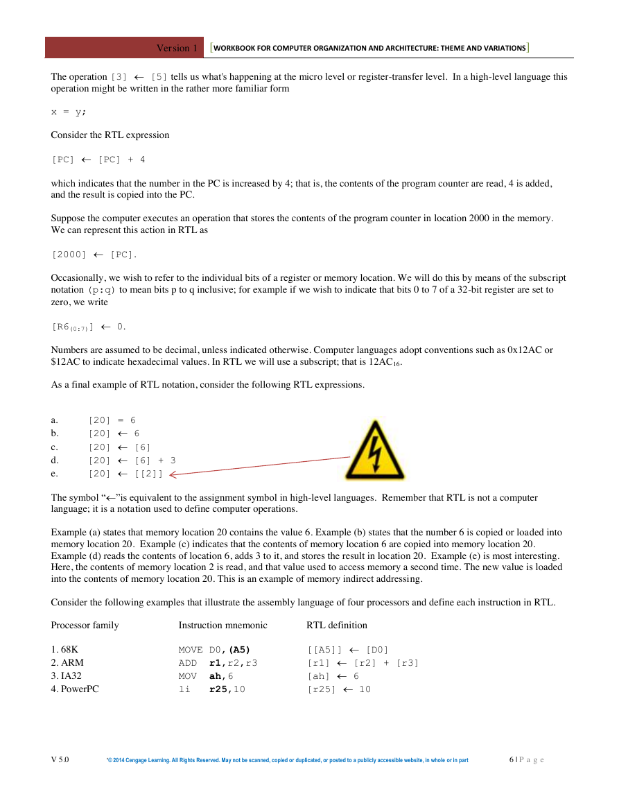
As a final example of RTL notation, consider the following RTL expressions.
a.
b.
c.
d.
e.
The symbol “”is equivalent to the assignment symbol in high-level languages. Remember that RTL is not a computer
language; it is a notation used to define computer operations.
Example (a) states that memory location 20 contains the value 6. Example (b) states that the number 6 is copied or loaded into
memory location 20. Example (c) indicates that the contents of memory location 6 are copied into memory location 20.
Example (d) reads the contents of location 6, adds 3 to it, and stores the result in location 20. Example (e) is most interesting.
Here, the contents of memory location 2 is read, and that value used to access memory a second time. The new value is loaded
into the contents of memory location 20. This is an example of memory indirect addressing.
Consider the following examples that illustrate the assembly language of four processors and define each instruction in RTL.
Processor family
1. 68K
2. ARM
3. IA32
4. PowerPC
[20] = 6
[20] 6
[20] [6]
[20] [6] + 3
[20] [[2]]
[[A5]] [D0]
[r1] [r2] + [r3]
[ah] 6
[r25] 10
Instruction mnemonic
RTL definition
MOVE D0,(A5)
ADD r1,r2,r3
MOV ah,6
li r25,10
V 5.0
“© 2014 Cengage Learning. All Rights Reserved. May not be scanned, copied or duplicated, or posted to a publicly accessible website, in whole or in part
6 | P a g e
�
Version 1
[WORKBOOK FOR COMPUTER ORGANIZATION AND ARCHITECTURE: THEME AND VARIATIONS]
RTL AND ASSEMBLY LANGUAGE
Don’t confuse RTL and assembly language. An assembly language is a human-readable form of a computer’s binary
code. It is designed to be used by programmers and may not always be logical or consistent. Some of you may notice
inconsistencies in the assembly language that we learn in this course.
RTL is a formal notation that can be manipulated like any algebraic expression. It offers a means of precisely defining
operations without using ambiguous English. Consider the RTL example:
Suppose that [4] = 3, [10] = 4, and [[10]] = y.
We can say that y = 3, because we can substitute y = [[10]] = [4] = 3
Similarly, [[4] + [10] + 6] = [3 + 4 + 6] = [13]
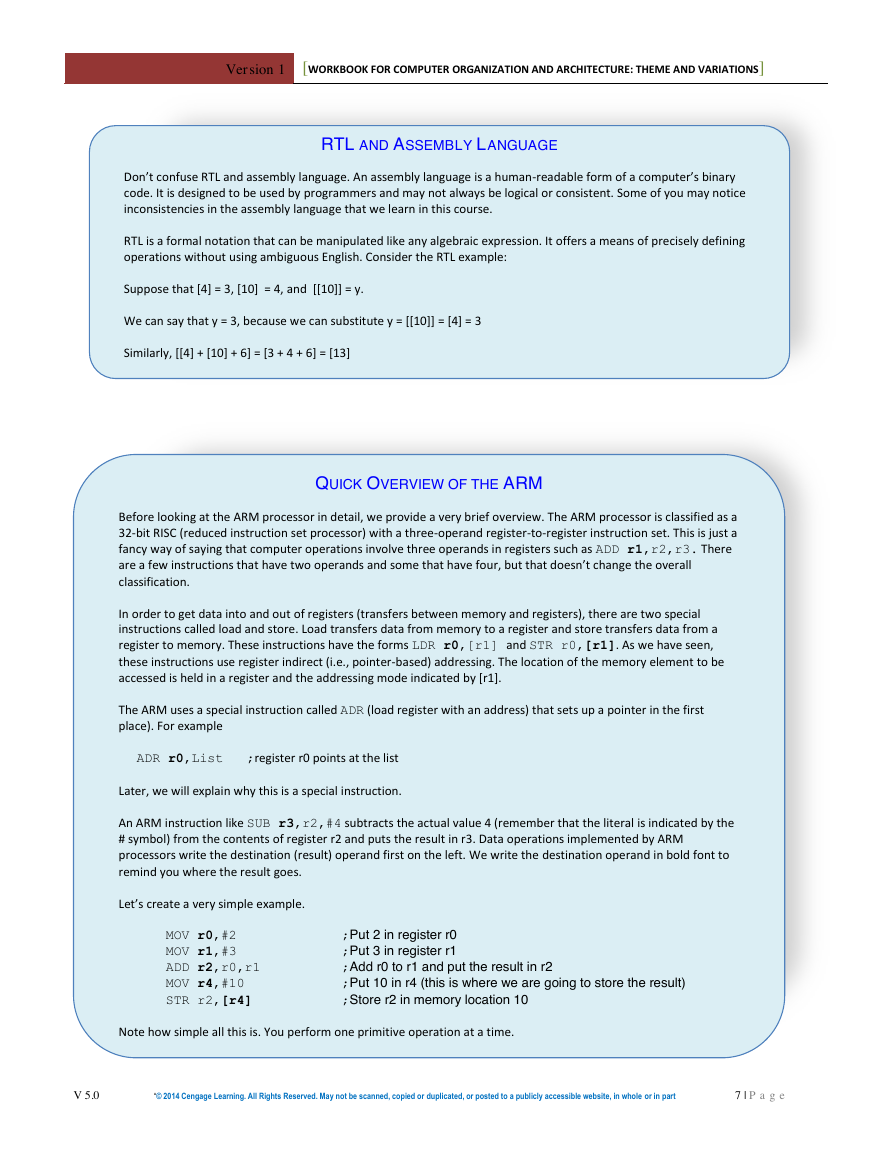
QUICK OVERVIEW OF THE ARM
Before looking at the ARM processor in detail, we provide a very brief overview. The ARM processor is classified as a
32-bit RISC (reduced instruction set processor) with a three-operand register-to-register instruction set. This is just a
fancy way of saying that computer operations involve three operands in registers such as ADD r1,r2,r3. There
are a few instructions that have two operands and some that have four, but that doesn’t change the overall
classification.
In order to get data into and out of registers (transfers between memory and registers), there are two special
instructions called load and store. Load transfers data from memory to a register and store transfers data from a
register to memory. These instructions have the forms LDR r0,[r1] and STR r0,[r1]. As we have seen,
these instructions use register indirect (i.e., pointer-based) addressing. The location of the memory element to be
accessed is held in a register and the addressing mode indicated by [r1].
The ARM uses a special instruction called ADR (load register with an address) that sets up a pointer in the first
place). For example
ADR r0,List ;register r0 points at the list
Later, we will explain why this is a special instruction.
An ARM instruction like SUB r3,r2,#4 subtracts the actual value 4 (remember that the literal is indicated by the
# symbol) from the contents of register r2 and puts the result in r3. Data operations implemented by ARM
processors write the destination (result) operand first on the left. We write the destination operand in bold font to
remind you where the result goes.
Let’s create a very simple example.
MOV r0,#2
MOV r1,#3
ADD r2,r0,r1
MOV r4,#10
STR r2,[r4]
Note how simple all this is. You perform one primitive operation at a time.
;Put 2 in register r0
;Put 3 in register r1
;Add r0 to r1 and put the result in r2
;Put 10 in r4 (this is where we are going to store the result)
;Store r2 in memory location 10
V 5.0
“© 2014 Cengage Learning. All Rights Reserved. May not be scanned, copied or duplicated, or posted to a publicly accessible website, in whole or in part
7 | P a g e
�



 2023年江西萍乡中考道德与法治真题及答案.doc
 2012年重庆南川中考生物真题及答案.doc
 2013年江西师范大学地理学综合及文艺理论基础考研真题.doc
 2020年四川甘孜小升初语文真题及答案I卷.doc
 2020年注册岩土工程师专业基础考试真题及答案.doc
 2023-2024学年福建省厦门市九年级上学期数学月考试题及答案.doc
 2021-2022学年辽宁省沈阳市大东区九年级上学期语文期末试题及答案.doc
 2022-2023学年北京东城区初三第一学期物理期末试卷及答案.doc
 2018上半年江西教师资格初中地理学科知识与教学能力真题及答案.doc
 2012年河北国家公务员申论考试真题及答案-省级.doc
 2020-2021学年江苏省扬州市江都区邵樊片九年级上学期数学第一次质量检测试题及答案.doc
 2022下半年黑龙江教师资格证中学综合素质真题及答案.doc