logo资料库

RTC5_Manual.zh.pdf

第1页 / 共692页
第2页 / 共692页
第3页 / 共692页
第4页 / 共692页
第5页 / 共692页
第6页 / 共692页
第7页 / 共692页
第8页 / 共692页
资料共692页,剩余部分请下载后查看
RTC®5PCIBoard, RTC®5 PCIExpress Board, RTC®5PC/104-Plus Board and RTC®5PCIe/104 Board
Contents
1 Introduction
1.1 Manufacturer
1.2 Labeling
1.3 Unpacking Instructions and Typical Package Contents
1.3.1 Delivered Software
2 Product Overview
2.1 Intended Use
2.2 System Requirements
2.2.1 Hardware
2.2.2 Software
2.3 Optional Functionality
2.4 Jumper Settings and Type Identification
2.4.1 Jumper JP1: Selecting the Output Signal Level at the EXTENSION1 Socket Connector
2.4.2 Jumper JP2–JP8: Configuring Pin15 and Pin17 at the EXTENSION 2 Socket Connector
2.4.3 Type Identification
2.5 Optional Accessories
2.5.1 XY2100 Converter
2.5.2 Data Cables
2.5.3 Laser Adapter
2.5.4 PCISlot Covers
2.5.5 ADC Add-On Board
2.5.6 RTC®5varioSCANFLEX Extension Board
2.6 Supplementary Software
2.7 Notes for RTC®4 Users
2.7.1 Hardware Changes
Scan System Control
Laser Control
EXTENSION1 Socket Connector
EXTENSION2 Socket Connector
MARKINGONTHEFLY Socket Connector
Other Interfaces
2.7.2 Porting RTC®4 Programs to the RTC®5
Changed Initialization
Command Changes
Increased Parameter Resolution
Changed Timing Behavior
2.7.3 New and Changed Functionality
Interface to the PC
Scan System Control
Laser Control
Interfaces for Peripheral Equipment
General Programming
Laser Marking
Special Functions
3 Safety During Installation and Operation
3.1 Steps for Safe Operation
3.2 Laser Safety
4 Layout and Interfaces
4.1 Connectors and Jumper Positions
4.2 Interface to PC
4.2.1 Master/Slave Synchronization
4.3 Interfaces to Scan System
4.3.1 Scan Head Connectors and Transfer Protocol
Primary Scan Head Connector
Secondary Scan Head Connector (Optionally Activated)
4.3.2 XY2100 Converter (Optional)
4.3.3 Data Cable (Optional)
4.4 Interfaces for the Laser and Peripheral Equipment
4.4.1 Laser Connector
Laser Signals
External Control Signals
BUSY Status
Digital Input and Output
Analog Output Ports
I/O Circuits
Laser Adapter (Optional)
4.4.2 EXTENSION1 Socket Connector
Configuring the Output Signal Level
16-Bit Digital Input and Output
Synchronization of Data Transmission
BUSY Status
4.4.3 EXTENSION2 Socket Connector
Jumper Setting
Laser Signals
8-Bit Digital Output Port
4.4.4 MARKINGONTHEFLY Socket Connector
Encoder Inputs
External Control Signals
Analog Output Port
BUSY Status
Slot Cover (Optional)
4.4.5 RS232 Socket Connector
4.4.6 SPI / I2C Socket Connector
Use as McBSP Interface
Use as I·C Interface
Use as SPI Interface
4.4.7 STEPPER MOTOR Socket Connector (Stepper Motor Control)
4.4.8 Analog Inputs (Optional)
5 Installation and Start-Up
5.1 Jumper Settings
5.2 Installing the RTC®5 Board
5.3 Installing the Drivers
5.3.1 Driver Upgrade
5.4 Installing the RTC®5 Software
5.5 Safe Start-up and Shutdown Sequences
5.6 Functionality Test
5.7 User Programs and Demo Software
5.8 Exchanging RTC®5 Boards
6 Developing User Programs
6.1 RTC®5 Software Basics
6.1.1 Controlling Scan Systems and Lasers – An Introductory Example
6.1.2 ListCommands and ControlCommands
6.2 Initialization and Program Start-Up
6.2.1 DLL Call
6.2.2 Importing Commands
Pascal
C
C++
C#
6.2.3 Initializing the DLL and Board Management
6.2.4 Start of Operation
RTC®5 Initialization
RTC®5 Configuration
Scan System Initialization
Laser Control Initialization
Loading and Executing Lists
6.2.5 Example Code
6.3 List Memory
6.3.1 Lists and the Protected Buffer Area
Lists
Protected Buffer Area
6.3.2 Configuring the List Memory
6.4 List Handling
6.4.1 Loading Lists
“Unconditional” Loading
Loading with Protection
Terminating Lists
6.4.2 List Status
6.4.3 List Execution Status
6.4.4 Starting and Stopping Lists
6.4.5 Interrupting Lists for Synchronization of Processing
6.4.6 Automatic List Changing
One-Time List Change
Alternating List Changes
6.5 Structured Programming
6.5.1 Subroutines
Non-Indexed Subroutines
Indexed Subroutines
Calling Subroutines
Subsequent Protection and Conversion of Non-Indexed Subroutines
Deprotecting Subroutines
Index Management and Defragmentation
6.5.2 Character Sets and Text Strings
Defining Indexed Character Sets
Calling Indexed Characters
Defining Indexed Text Strings for Times, Dates and Serial Numbers
Calling Indexed Text Strings
Management of Indexed Characters and Text Strings
6.5.3 Jumps
6.5.4 Circular Queue Mode
6.5.5 Loops
6.6 Using Multiple RTC®5 Boards in One Computer
6.6.1 Multi-Board Programming
6.6.2 Sequential Programming
6.6.3 Master/Slave Operation
Initialization
Clock Phase Synchronization
Matching of Short-Command Counts (as of Version DLL523, OUT524)
Synchronous Starts and Stops
6.7 Usage by Multiple Applications
6.7.1 Board Acquisition by a User Program
6.8 Error Handling
6.8.1 Download Verification
6.8.2 Checking for Overruns
6.8.3 Example Code
6.9 Miscellaneous
6.9.1 Free Variables
7 Basic Functions for Scan Head and Laser Control
7.1 Marking Points, Lines and Arcs
7.1.1 Marking with Vector and Arc Commands
Jump Commands
Mark Commands
Arc Commands
Ellipse Commands
Para Commands
7.1.2 Microsteps
7.1.3 Marking Points
7.1.4 Example Code
7.2 Delay Settings for Synchronizing Scan Head and Laser Control
7.2.1 Laser Delays
LaserOn Delay
LaserOff Delay
7.2.2 Scanner Delays
Jump Delay
Variable Jump Delay
Mark Delay
Polygon Delay
Variable Polygon Delay
Customizing the Variable Polygon Delay
7.2.3 Notes on Optimizing the Delays
Recommended Sequence
Automatic Delay Adjustments
Optimizing the Delays
7.2.4 Sky Writing
Mode1
Mode2
Mode3
Synchronization
7.3 Scan Head Control
7.3.1 Reference System
7.3.2 Image Field Size and Calibration
Typical Image Field
RTC®4 Compatibility Mode
7.3.3 Virtual Image Field
7.3.4 Image Field Correction and Correction Tables
Field Distortion
Field Correction Algorithm
Activating Image Field Correction
2D and 3D Correction Files
Loading Correction Tables
Assigning Loaded Correction Tables
1to1 Correction Tables
Inverse Tables
Correction File Header
Converting Correction Files
7.3.5 Output Values to the Scan System
Calculations
Value Ranges
Precalculation and Diagnosis
Clock Overruns
7.3.6 Status Monitoring and Diagnostics
Status Information Returned from the Scan System
7.4 Laser Control
7.4.1 Enabling, Activating and Switching Laser Control Signals
“LaserActive” Signals
“LaserStandby” Signals
Scan-System-Error-Induced Laser-Signal Auto-Suppression
Galvanometer Position Exceedance-Induced Laser-Signal Auto-Suppression
7.4.2 Configuring the Laser Connector (LASER)
7.4.3 CO2 Mode
7.4.4 YAG Modes
QSwitch Signal
FirstPulseKiller Signal
Differences Between the YAG Modes
Lamp Current (Laser Power)
7.4.5 Softstart Mode
7.4.6 Laser Mode 4
7.4.7 Laser Mode 6
7.4.8 Pulse Picking Laser Mode
7.4.9 Automatic Laser Control
Position-Dependent Laser Control
Speed-Dependent Laser Control
Vector-Defined Laser Control
Encoder-Speed-Dependent Laser Control
7.4.10 Output Synchronization
7.5 Marking Dates, Times and Serial Numbers
7.5.1 Marking the Date and Time
7.5.2 Marking Serial Numbers
8 Advanced Functions for Scan Head and Laser Control
8.1 iDRIVE® Functions
8.1.1 Transfer Protocol
8.1.2 Configuring Status Return Behavior
Selecting Data Signals
Querying Data
8.1.3 Position Monitoring
8.1.4 Configuring Dynamics Settings (Tuning)
8.1.5 Jump Mode
Functional Principle
Requirements and Activation
Jump-Length-Dependent Jump Delays
Experimental Determination of Jump Delay Values
Notes on Loading Determined Jump Delay Values
Automatic Determination of the Jump Delay Table
8.1.6 Configuring the PosAcknowledge Threshold Value
8.1.7 Configuring the Effective Calibration
8.1.8 Configuring the Start Behavior
8.1.9 Fault Diagnosis and Functional Test
8.2 Coordinate Transformations
8.3 Online Positioning
Configuring Online Positioning
8.4 Wobbel Mode
8.4.1 Wobbel Shapes – Important Notes on Choosing Appropriate Parameter Values
“Classic” Wobbel Shapes
“Freely Definable Wobbel Shapes”
8.5 Using Several Different Correction Tables
8.5.1 Configuration with Two 2D Scan Systems
8.5.2 Using Several Correction Tables with a Single Scan System
8.6 Controlling a 3Axis Scan System (Optional)
8.6.1 Intended Use
8.6.2 Connection and Initialization
8.6.3 3D Marking Commands
8.6.4 Adjustment
Checking the Z-Axis Calibration
Test for 3-Axis Scan Systems with FTheta Objective
8.6.5 Enhanced 3D Correction
8.7 Processing-on-the-fly (Optional)
8.7.1 Intended Use and Initialization
Overview
8.7.2 Compensation of Linear Movements
Correction by Encoder Counter(s)
Correction by McBSP/SPI Interface
Correction by McBSP/SPI Interface with Additional McBSP/SPI Input
Correction by McBSP/SPI Interface with Enhanced McBSP/SPI Input
8.7.3 Compensation of Rotary Movements
Correction by Encoder Counter
Correction by McBSP/SPI Interface
Correction by McBSP/SPI Interface with Additional McBSP/SPI Input
8.7.4 Compensation of 2D Motions
2D Encoder Compensation for XY Stages
Coordinate Transformations in the Virtual Image Field
8.7.5 Deactivating Processing-on- the-fly Corrections
8.7.6 Virtual Image Field
8.7.7 Synchronization of Processing- on-the-fly Applications
8.7.8 Encoder Resets
8.7.9 Monitoring Processing-on-the- fly Corrections
Customer-Defined Monitoring Area and Conditional Command Execution (as of Version DLL525, OUT527)
8.7.10 Tracking Error Compensation of Encoder Values for Processing-on-the-fly Applications
8.8 Scanning Raster Images (Bitmaps)
8.8.1 Principle Of Operation
8.8.2 Software Commands
8.8.3 Laser Control
8.8.4 Timing
8.9 Microvector Commands
8.10 Timed Vector and Arc Commands
8.11 Automatic Self-Calibration
8.11.1 Using for Drift Compensation
8.11.2 How it Works
8.11.3 Determining Reference Values
8.11.4 Calibration During the Application
Automatic Self-Calibration
Customer-Specific Calibration
Supplemental Information about Calibration
8.12 Camming
9 Programming Peripheral Interfaces
9.1 Signal Output
9.1.1 16-Bit Digital Output Port
9.1.2 8-Bit Digital Output Port
9.1.3 2Bit Digital Output Port
9.1.4 12-Bit Analog Output Ports
9.1.5 Stepper Motor Control
Output Signals
Reference Movements and Position Initialization
Set-Position Movements
Querying Signals and Status Values
Terminating Infinite Movements
9.1.6 RS232 Interface
9.1.7 McBSP/SPI Interface
9.2 Signal Input
9.2.1 16-Bit Digital Input
9.2.2 2-Bit Digital Input
9.2.3 RS232 Interface
9.2.4 McBSP/SPI Interface
9.3 Control by External Signals
9.3.1 Starting and Stopping Lists by External Control Signals and Master/Slave Synchronization
External List Stop
External List Start
External List Start with Track Delay
Regular (Periodic) External List Starts
9.3.2 Conditional Command Execution
Programming Examples
9.3.3 Synchronization by Encoder Signals
Intended Use
Inputs for External Encoder Signals
Encoder Simulation
9.3.4 Synchronization and Online Positioning by McBSP/SPI Signals
9.4 Periodical I/O Signals
10 Commands and Functions
10.1 Overview
10.1.1 Nomenclature
Multi-Board Commands
Normal, Short and Variable List Commands and List Multi-Commands
Undelayed and Delayed Short List Commands (as of Version OUT515)
List Multi-Commands
10.1.2 Compatibility
10.1.3 Version Information
10.1.4 Optional Functions
10.1.5 Control Commands
10.1.6 List Commands
10.1.7 Data Types
10.2 RTC®5 Command Set
acquire_rtc
activate_fly_2d
activate_fly_xy
apply_mcbsp
apply_mcbsp_list
arc_abs
arc_abs_3d
arc_rel
arc_rel_3d
auto_cal
auto_change
auto_change_pos
bounce_supp
camming
clear_fly_overflow
clear_io_cond_list
config_laser_signals
config_laser_signals_list
config_list
control_command
copy_dst_src
disable_laser
enable_laser
execute_at_pointer
execute_list
execute_list_1
execute_list_2
execute_list_pos
fly_return
fly_return_z
free_rtc5_dll
get_auto_cal
get_char_pointer
get_config_list
get_counts
get_dll_version
get_encoder
get_error
get_fly_2d_offset
get_free_variable
get_galvo_controls
get_head_para
get_head_status
get_hex_version
get_hi_data
get_hi_pos
get_input_pointer
get_io_status
get_jump_table
get_laser_pin_in
get_last_error
get_list_pointer
get_list_serial
get_list_space
get_marking_info
get_master_slave
get_mcbsp
get_mcbsp_list
get_out_pointer
get_overrun
get_rtc_mode
get_rtc_version
get_serial
get_serial_number
get_standby
get_startstop_info
get_status
get_stepper_status
get_sub_pointer
get_sync_status
get_table_para
get_text_table_pointer
get_time
get_transform
get_value
get_values
get_wait_status
get_waveform
get_z_distance
goto_xy
goto_xyz
home_position
home_position_xyz
if_cond
if_fly_x_overflow
if_fly_y_overflow
if_fly_z_overflow
if_not_activated
if_not_cond
if_not_fly_x_overflow
if_not_fly_y_overflow
if_not_fly_z_overflow
if_not_pin_cond
if_pin_cond
init_fly_2d
init_rtc5_dll
jump_abs
jump_abs_3d
jump_rel
jump_rel_3d
laser_on_list
laser_on_pulses_list
laser_signal_off
laser_signal_off_list
laser_signal_on
laser_signal_on_list
list_call
list_call_abs
list_call_abs_cond
list_call_cond
list_continue
list_jump_cond
list_jump_pos
list_jump_pos_cond
list_jump_rel
list_jump_rel_cond
list_nop
list_repeat
list_return
list_until
load_auto_laser_control
load_char
load_correction_file
load_disk
load_fly_2d_table
load_jump_table
load_jump_table_offset
load_list
load_position_control
load_program_file
load_stretch_table
load_sub
load_text_table
load_varpolydelay
load_z_table
long_delay
mark_abs
mark_abs_3d
mark_char
mark_char_abs
mark_date
mark_date_abs
mark_ellipse_abs
mark_ellipse_rel
mark_rel
mark_rel_3d
mark_serial
mark_serial_abs
mark_text
mark_text_abs
mark_time
mark_time_abs
mcbsp_init
mcbsp_init_spi
measurement_status
micro_vector_abs
micro_vector_abs_3d
micro_vector_rel
micro_vector_rel_3d
move_to
para_jump_abs
para_jump_abs_3d
para_jump_rel
para_jump_rel_3d
para_laser_on_pulses_list
para_mark_abs
para_mark_abs_3d
para_mark_rel
para_mark_rel_3d
park_position
park_return
pause_list
periodic_toggle
periodic_toggle_list
quit_loop
range_checking
read_abc_from_file
read_analog_in
read_encoder
read_io_port
read_io_port_buffer
read_io_port_list
read_mcbsp
read_multi_mcbsp
read_status
read_user_data
release_rtc
release_wait
reset_error
restart_list
rs232_config
rs232_read_data
rs232_write_data
rs232_write_text
rs232_write_text_list
rtc5_count_cards
save_and_restart_timer
save_disk
select_char_set
select_cor_table
select_cor_table_list
select_rtc
select_serial_set
select_serial_set_list
send_user_data
set_angle
set_angle_list
set_auto_laser_control
set_auto_laser_params
set_auto_laser_params_list
set_char_pointer
set_char_table
set_control_mode
set_control_mode_list
set_default_pixel
set_default_pixel_list
set_defocus
set_defocus_list
set_delay_mode
set_delay_mode_list
set_dsp_mode
set_ellipse
set_encoder_speed
set_encoder_speed_ctrl
set_end_of_list
set_extstartpos
set_extstartpos_list
set_ext_start_delay
set_ext_start_delay_list
set_firstpulse_killer
set_firstpulse_killer_list
set_fly_2d
set_fly_limits
set_fly_limits_z
set_fly_rot
set_fly_rot_pos
set_fly_tracking_error
set_fly_x
set_fly_x_pos
set_fly_y
set_fly_y_pos
set_free_variable
set_free_variable_list
set_hi
set_input_pointer
set_io_cond_list
set_jump_mode
set_jump_mode_list
set_jump_speed
set_jump_speed_ctrl
set_jump_table
set_laser_control
set_laser_delays
set_laser_mode
set_laser_off_default
set_laser_pin_out
set_laser_pin_out_list
set_laser_pulses
set_laser_pulses_ctrl
set_laser_timing
set_list_jump
set_mark_speed
set_mark_speed_ctrl
set_matrix
set_matrix_list
set_max_counts
set_mcbsp_freq
set_mcbsp_in
set_mcbsp_in_list
set_mcbsp_matrix
set_mcbsp_matrix_list
set_mcbsp_out
set_mcbsp_out_ptr
set_mcbsp_rot
set_mcbsp_rot_list
set_mcbsp_x
set_mcbsp_x_list
set_mcbsp_y
set_mcbsp_y_list
set_multi_mcbsp_in
set_multi_mcbsp_in_list
set_n_pixel
set_offset
set_offset_list
set_offset_xyz
set_offset_xyz_list
set_pixel
set_pixel_line
set_pixel_line_3d
set_port_default
set_pulse_picking
set_pulse_picking_length
set_pulse_picking_list
set_qswitch_delay
set_qswitch_delay_list
set_rot_center
set_rot_center_list
set_rtc4_mode
set_rtc5_mode
set_scale
set_scale_list
set_scanner_delays
set_serial
set_serial_step
set_serial_step_list
set_sky_writing
set_sky_writing_limit
set_sky_writing_limit_list
set_sky_writing_list
set_sky_writing_mode
set_sky_writing_mode_list
set_sky_writing_para
set_sky_writing_para_list
set_softstart_level
set_softstart_level_list
set_softstart_mode
set_softstart_mode_list
set_standby
set_standby_list
set_start_list
set_start_list_1
set_start_list_2
set_start_list_pos
set_sub_pointer
set_text_table_pointer
set_trigger
set_trigger4
set_vector_control
set_verify
set_wait
set_wobbel
set_wobbel_control
set_wobbel_direction
set_wobbel_mode
set_wobbel_offset
set_wobbel_vector
simulate_encoder
simulate_ext_start
simulate_ext_start_ctrl
simulate_ext_stop
start_loop
stepper_abs
stepper_abs_list
stepper_abs_no
stepper_abs_no_list
stepper_control
stepper_control_list
stepper_enable
stepper_enable_list
stepper_init
stepper_rel
stepper_rel_list
stepper_rel_no
stepper_rel_no_list
stepper_wait
stop_execution
stop_list
stop_trigger
store_encoder
sub_call
sub_call_abs
sub_call_abs_cond
sub_call_abs_repeat
sub_call_cond
sub_call_repeat
switch_ioport
sync_slaves
time_fix
time_fix_f
time_fix_f_off
time_update
timed_arc_abs
timed_arc_rel
timed_jump_abs
timed_jump_abs_3d
timed_jump_rel
timed_jump_rel_3d
timed_mark_abs
timed_mark_abs_3d
timed_mark_rel
timed_mark_rel_3d
timed_para_jump_abs
timed_para_jump_abs_3d
timed_para_jump_rel
timed_para_jump_rel_3d
timed_para_mark_abs
timed_para_mark_abs_3d
timed_para_mark_rel
timed_para_mark_rel_3d
transform
upload_transform
verify_checksum
wait_for_encoder
wait_for_encoder_in_range
wait_for_encoder_mode
wait_for_mcbsp
write_8bit_port
write_8bit_port_list
write_abc_to_file
write_da_1
write_da_1_list
write_da_2
write_da_2_list
write_da_x
write_da_x_list
write_hi_pos
write_io_port
write_io_port_list
write_io_port_mask
write_io_port_mask_list
10.3 Unsupported RTC®2/RTC®3/RTC®4 Commands
11 Demo Programs
12 Troubleshooting
13 Customer Service
13.1 Servicing and Repairs
13.2 Warranty
13.3 Contacting SCANLAB
13.4 Product Disposal
14 Technical Specifications of the RTC®5PCIBoard
14.1 Compliance with EC Guidelines for Electromagnetic Compatibility (EMC)
14.2 Compliance with FCC Rules
15 Appendix A: The RTC®5PC/104-Plus Board
15.1 Product Overview
15.1.1 Intended Use – Comparison to the RTC®5PCIBoard
15.1.2 System Requirements
Hardware
Software
15.1.3 Optional Functionality
15.1.4 Labeling
15.1.5 Type Identification
15.1.6 Unpacking Instructions and Typical Package Contents
Delivered Software
15.1.7 Optional Accessories
15.1.8 Supplementary Software
15.2 Layout and Interfaces
15.2.1 Connectors and Jumper Positions
15.2.2 Interface to the CPU board
15.2.3 Master/Slave Synchronization
15.2.4 Interfaces to Scan System
15.2.5 Interfaces for the Laser and Peripheral Equipment
LASER connector
MULTI connector
15.3 Installation and Start-Up
15.3.1 Safety During Installation and Operation
15.3.2 Jumper Settings
Jumper 17+18: Setting the Binary Stack Address
JP19: +5V Power Supply
JP10+12: 10V Output Voltage for ANALOGOUT1 and ANALOGOUT2
Jumper JP1: Selecting the Output Signal Level at the MULTI connector
Jumper JP2-JP8: Configuring PinB40 and PinB42 at the MULTI connector
15.3.3 Installing the RTC®5PC/104- Plus Board
15.3.4 Installing the Drivers and the RTC®5 Software
15.3.5 Functionality Test, User Programs and Demo Software
15.4 Technical Specifications of RTC®5PC/104-Plus Board
16 Appendix B: The RTC®5 PCIExpress Board
16.1 Product Overview
16.1.1 Intended Use – Comparison to the RTC®5PCIBoard
16.1.2 System Requirements
Hardware
Software
16.1.3 Optional Functionality
16.1.4 Labeling
16.1.5 Type Identification
16.1.6 Unpacking Instructions and Typical Package Contents
Delivered Software
16.1.7 Optional Accessories
16.1.8 Supplementary Software
16.2 Layout and Interfaces
16.2.1 Connectors and Jumper Positions
16.2.2 Interface to PC
16.2.3 McBSP/SPI Interface and Analog Inputs
McBSP/SPI Interface
Analog Inputs
16.3 Installation and Start-Up
16.4 Technical Specifications of the RTC®5 PCIExpress Board
16.5 Compliance with EC Guidelines for Electromagnetic Compatibility (EMC)
16.6 Compliance with FCC Rules
17 Appendix C: The RTC®5PCIe/104 Board
17.1 Product Overview
17.1.1 Intended Use – Comparison to the RTC®5PCIBoard
17.1.2 Comparison to the RTC®5PC/104-Plus board
17.1.3 System Requirements
Hardware
Software
17.1.4 Optional Functionality
17.1.5 Optional Connector
17.1.6 Labeling
17.1.7 Type Identification
17.1.8 Unpacking Instructions and Typical Package Contents
Delivered Software
17.1.9 Optional Accessories
17.1.10 Supplementary Software
17.2 Layout and Interfaces
17.2.1 Connectors and Jumper Positions
17.2.2 Interface to the CPU board
17.2.3 Master/Slave Synchronization
17.2.4 Interfaces to Scan System
17.2.5 Interfaces for the Laser and Peripheral Equipment
17.3 Installation and Start-Up
17.4 Technical Specifications of RTC®5PCIe/104 Board
18 Revision History
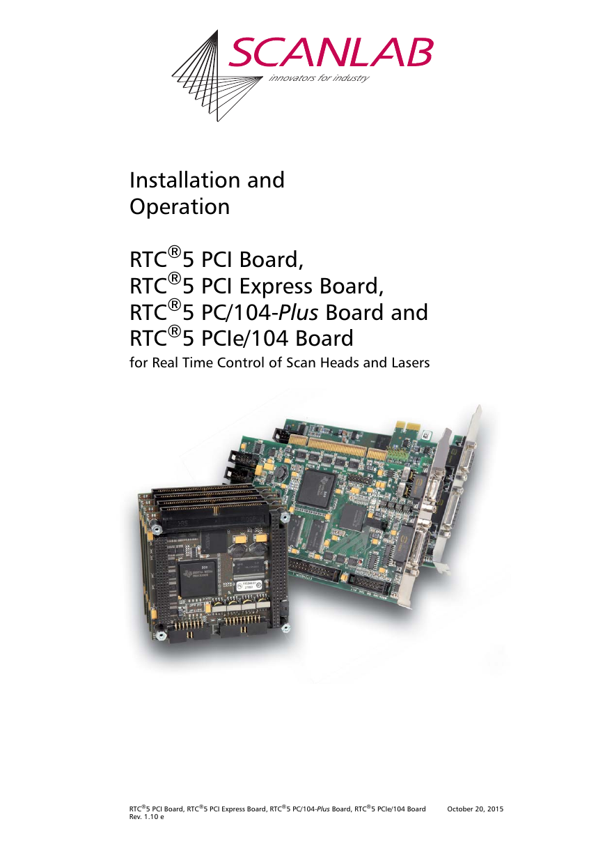
innovators for industry Installation and Operation RTC®5 PCI Board, RTC®5 PCI Express Board, RTC®5 PC/104-Plus Board and RTC®5 PCIe/104 Board for Real Time Control of Scan Heads and Lasers RTC®5 PCI Board, RTC®5 PCI Express Board, RTC®5 PC/104-Plus Board, RTC®5 PCIe/104 Board Rev. 1.10 e October 20, 2015
SCANLAB AG Siemensstr. 2a 82178 Puchheim Germany Tel. +49 (89) 800 746-0 Fax: +49 (89) 800 746-199 info@scanlab.de www.scanlab.de © SCANLAB AG 2015 (Doc. Rev. 1.10 e - October 30, 2015) SCANLAB reserves the right to change the information in this document without notice. No part of this manual may be processed, reproduced or distributed in any form (photocopy, print, microfilm or by any other means), electronic or mechanical, for any purpose without the written permission of SCANLAB. RTC® is a registered trademark of SCANLAB AG. PC/104-Plus and PCIe/104 are a registered trademarks of the “PC/104 Embedded Consortium”. Other mentioned trademarks are hereby acknowledged as properties of their respective owners.
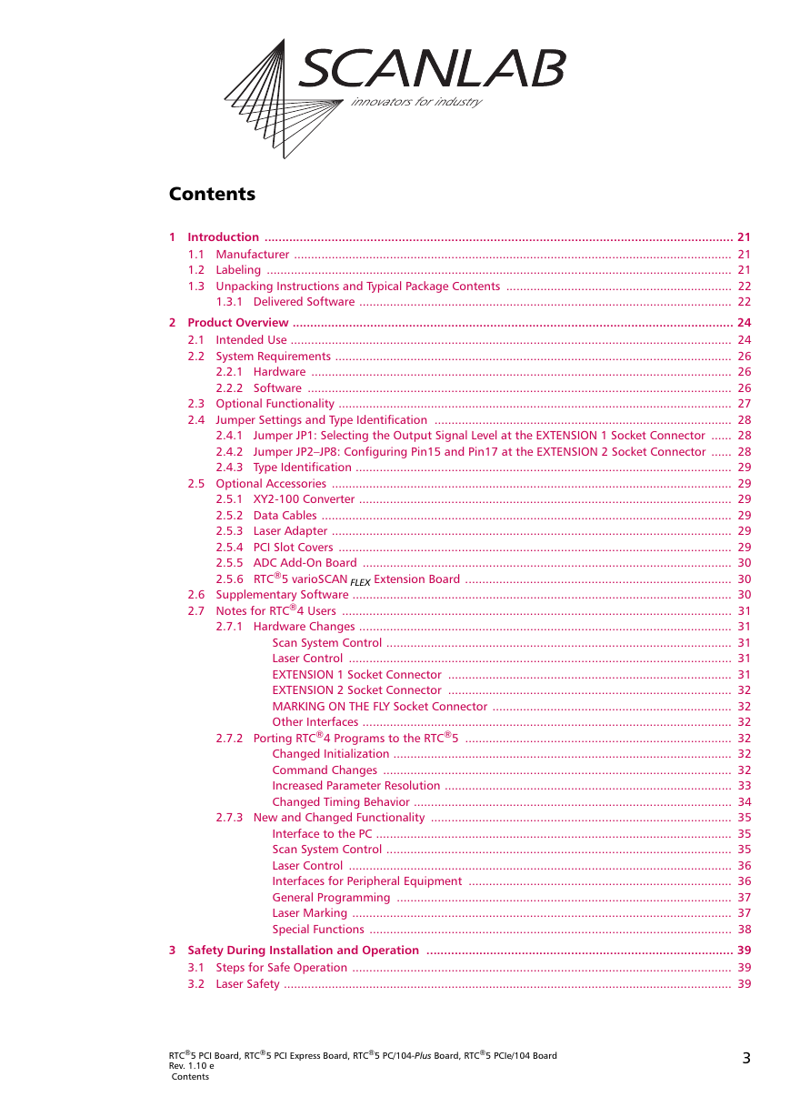
innovators for industry Contents 1 Introduction ..................................................................................................................................... 21 1.1 Manufacturer ................................................................................................................................ 21 1.2 Labeling ........................................................................................................................................ 21 1.3 Unpacking Instructions and Typical Package Contents .................................................................. 22 1.3.1 Delivered Software ............................................................................................................. 22 2 Product Overview ............................................................................................................................. 24 2.1 Intended Use ................................................................................................................................. 24 2.2 System Requirements .................................................................................................................... 26 2.2.1 Hardware ........................................................................................................................... 26 2.2.2 Software ............................................................................................................................ 26 2.3 Optional Functionality ................................................................................................................... 27 2.4 Jumper Settings and Type Identification ....................................................................................... 28 2.4.1 Jumper JP1: Selecting the Output Signal Level at the EXTENSION 1 Socket Connector ...... 28 2.4.2 Jumper JP2–JP8: Configuring Pin15 and Pin17 at the EXTENSION 2 Socket Connector ...... 28 2.4.3 Type Identification .............................................................................................................. 29 2.5 Optional Accessories ..................................................................................................................... 29 2.5.1 XY2-100 Converter ............................................................................................................. 29 2.5.2 Data Cables ........................................................................................................................ 29 2.5.3 Laser Adapter ..................................................................................................................... 29 2.5.4 PCI Slot Covers ................................................................................................................... 29 2.5.5 ADC Add-On Board ............................................................................................................ 30 2.5.6 RTC®5 varioSCAN FLEX Extension Board .............................................................................. 30 2.6 Supplementary Software ............................................................................................................... 30 2.7 Notes for RTC®4 Users .................................................................................................................. 31 2.7.1 Hardware Changes ............................................................................................................. 31 Scan System Control ..................................................................................................... 31 Laser Control ................................................................................................................ 31 EXTENSION 1 Socket Connector ................................................................................... 31 EXTENSION 2 Socket Connector ................................................................................... 32 MARKING ON THE FLY Socket Connector ...................................................................... 32 Other Interfaces ............................................................................................................ 32 2.7.2 Porting RTC®4 Programs to the RTC®5 .............................................................................. 32 Changed Initialization ................................................................................................... 32 Command Changes ...................................................................................................... 32 Increased Parameter Resolution .................................................................................... 33 Changed Timing Behavior ............................................................................................. 34 2.7.3 New and Changed Functionality ........................................................................................ 35 Interface to the PC ........................................................................................................ 35 Scan System Control ..................................................................................................... 35 Laser Control ................................................................................................................ 36 Interfaces for Peripheral Equipment ............................................................................. 36 General Programming .................................................................................................. 37 Laser Marking ............................................................................................................... 37 Special Functions .......................................................................................................... 38 3 Safety During Installation and Operation ....................................................................................... 39 3.1 Steps for Safe Operation ............................................................................................................... 39 3.2 Laser Safety ................................................................................................................................... 39 RTC®5 PCI Board, RTC®5 PCI Express Board, RTC®5 PC/104-Plus Board, RTC®5 PCIe/104 Board Rev. 1.10 e Contents 3
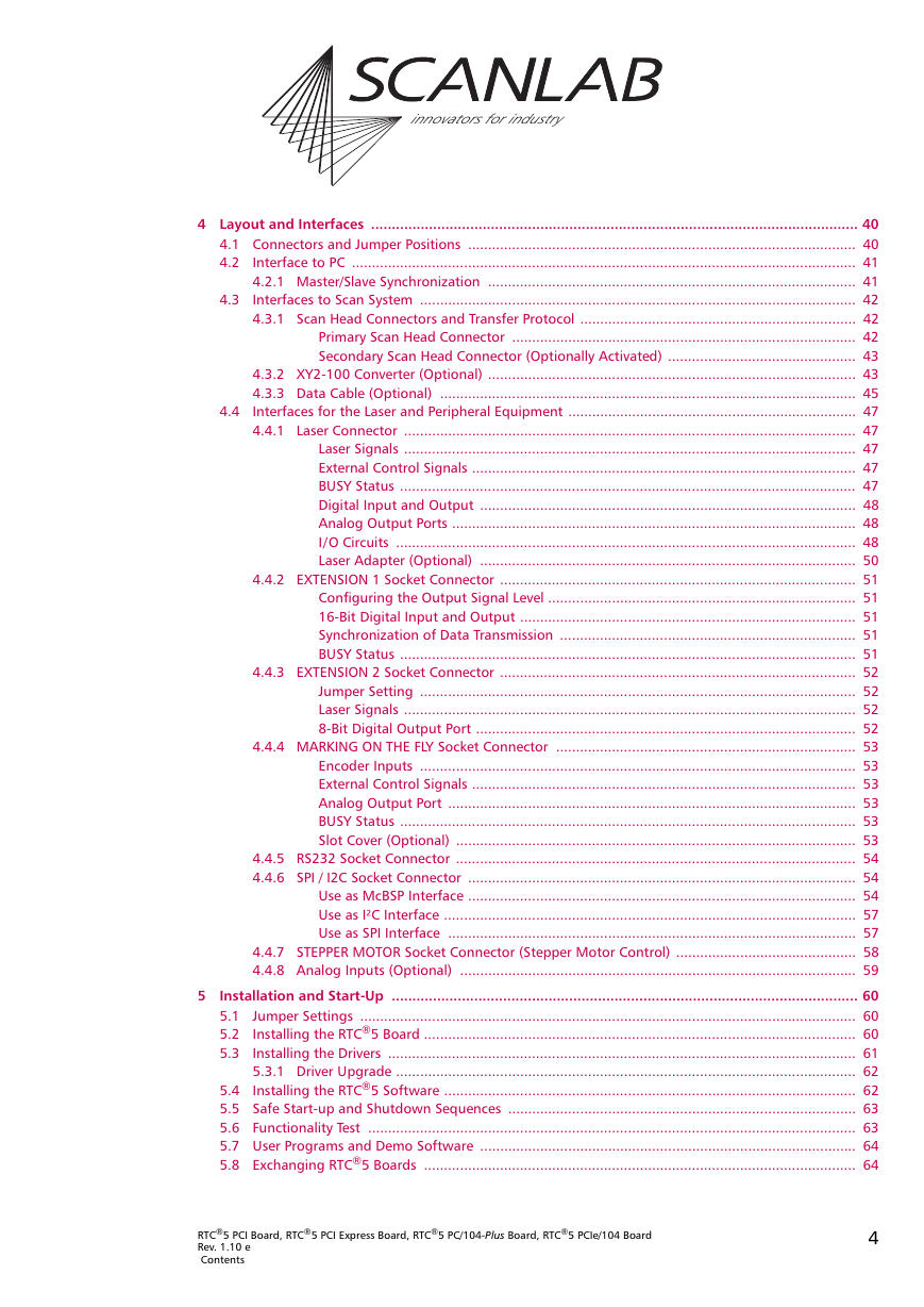
innovators for industry 4 Layout and Interfaces ...................................................................................................................... 40 4.1 Connectors and Jumper Positions ................................................................................................. 40 4.2 Interface to PC .............................................................................................................................. 41 4.2.1 Master/Slave Synchronization ............................................................................................ 41 4.3 Interfaces to Scan System ............................................................................................................. 42 4.3.1 Scan Head Connectors and Transfer Protocol ..................................................................... 42 Primary Scan Head Connector ...................................................................................... 42 Secondary Scan Head Connector (Optionally Activated) ............................................... 43 4.3.2 XY2-100 Converter (Optional) ............................................................................................ 43 4.3.3 Data Cable (Optional) ........................................................................................................ 45 4.4 Interfaces for the Laser and Peripheral Equipment ........................................................................ 47 4.4.1 Laser Connector ................................................................................................................. 47 Laser Signals ................................................................................................................. 47 External Control Signals ................................................................................................ 47 BUSY Status .................................................................................................................. 47 Digital Input and Output .............................................................................................. 48 Analog Output Ports ..................................................................................................... 48 I/O Circuits ................................................................................................................... 48 Laser Adapter (Optional) .............................................................................................. 50 4.4.2 EXTENSION 1 Socket Connector ......................................................................................... 51 Configuring the Output Signal Level ............................................................................. 51 16-Bit Digital Input and Output .................................................................................... 51 Synchronization of Data Transmission .......................................................................... 51 BUSY Status .................................................................................................................. 51 4.4.3 EXTENSION 2 Socket Connector ......................................................................................... 52 Jumper Setting ............................................................................................................. 52 Laser Signals ................................................................................................................. 52 8-Bit Digital Output Port ............................................................................................... 52 4.4.4 MARKING ON THE FLY Socket Connector ........................................................................... 53 Encoder Inputs ............................................................................................................. 53 External Control Signals ................................................................................................ 53 Analog Output Port ...................................................................................................... 53 BUSY Status .................................................................................................................. 53 Slot Cover (Optional) .................................................................................................... 53 4.4.5 RS232 Socket Connector .................................................................................................... 54 4.4.6 SPI / I2C Socket Connector ................................................................................................. 54 Use as McBSP Interface ................................................................................................. 54 Use as I²C Interface ....................................................................................................... 57 Use as SPI Interface ...................................................................................................... 57 4.4.7 STEPPER MOTOR Socket Connector (Stepper Motor Control) ............................................. 58 4.4.8 Analog Inputs (Optional) ................................................................................................... 59 5 Installation and Start-Up ................................................................................................................. 60 5.1 Jumper Settings ............................................................................................................................ 60 5.2 Installing the RTC®5 Board ............................................................................................................ 60 5.3 Installing the Drivers ..................................................................................................................... 61 5.3.1 Driver Upgrade ................................................................................................................... 62 5.4 Installing the RTC®5 Software ....................................................................................................... 62 5.5 Safe Start-up and Shutdown Sequences ....................................................................................... 63 5.6 Functionality Test .......................................................................................................................... 63 5.7 User Programs and Demo Software .............................................................................................. 64 5.8 Exchanging RTC®5 Boards ............................................................................................................ 64 RTC®5 PCI Board, RTC®5 PCI Express Board, RTC®5 PC/104-Plus Board, RTC®5 PCIe/104 Board Rev. 1.10 e Contents 4
innovators for industry 6 Developing User Programs .............................................................................................................. 65 6.1 RTC®5 Software Basics .................................................................................................................. 65 6.1.1 Controlling Scan Systems and Lasers – An Introductory Example ....................................... 65 6.1.2 List Commands and Control Commands ............................................................................ 65 6.2 Initialization and Program Start-Up ............................................................................................... 66 6.2.1 DLL Call .............................................................................................................................. 66 6.2.2 Importing Commands ........................................................................................................ 66 Pascal ........................................................................................................................... 66 C ................................................................................................................................... 67 C++ ............................................................................................................................... 67 C# ................................................................................................................................. 67 6.2.3 Initializing the DLL and Board Management ...................................................................... 68 6.2.4 Start of Operation .............................................................................................................. 69 RTC®5 Initialization ...................................................................................................... 69 RTC®5 Configuration .................................................................................................... 69 Scan System Initialization ............................................................................................. 69 Laser Control Initialization ............................................................................................ 69 Loading and Executing Lists ......................................................................................... 70 6.2.5 Example Code .................................................................................................................... 71 6.3 List Memory .................................................................................................................................. 73 6.3.1 Lists and the Protected Buffer Area .................................................................................... 73 Lists .............................................................................................................................. 73 Protected Buffer Area ................................................................................................... 73 6.3.2 Configuring the List Memory ............................................................................................. 74 6.4 List Handling ................................................................................................................................. 75 6.4.1 Loading Lists ...................................................................................................................... 75 “Unconditional” Loading .............................................................................................. 75 Loading with Protection ............................................................................................... 75 Terminating Lists ........................................................................................................... 76 6.4.2 List Status .......................................................................................................................... 76 6.4.3 List Execution Status .......................................................................................................... 77 6.4.4 Starting and Stopping Lists ................................................................................................ 78 6.4.5 Interrupting Lists for Synchronization of Processing .......................................................... 79 6.4.6 Automatic List Changing .................................................................................................... 79 One-Time List Change ................................................................................................... 79 Alternating List Changes ............................................................................................... 80 6.5 Structured Programming .............................................................................................................. 80 6.5.1 Subroutines ........................................................................................................................ 80 Non-Indexed Subroutines ............................................................................................. 80 Indexed Subroutines ..................................................................................................... 81 Calling Subroutines ...................................................................................................... 82 Subsequent Protection and Conversion of Non-Indexed Subroutines ........................... 83 Deprotecting Subroutines ............................................................................................. 84 Index Management and Defragmentation .................................................................... 84 6.5.2 Character Sets and Text Strings .......................................................................................... 86 Defining Indexed Character Sets ................................................................................... 86 Calling Indexed Characters ........................................................................................... 86 Defining Indexed Text Strings for Times, Dates and Serial Numbers .............................. 87 Calling Indexed Text Strings .......................................................................................... 87 Management of Indexed Characters and Text Strings ................................................... 87 6.5.3 Jumps ................................................................................................................................ 88 6.5.4 Circular Queue Mode ......................................................................................................... 88 RTC®5 PCI Board, RTC®5 PCI Express Board, RTC®5 PC/104-Plus Board, RTC®5 PCIe/104 Board Rev. 1.10 e Contents 5
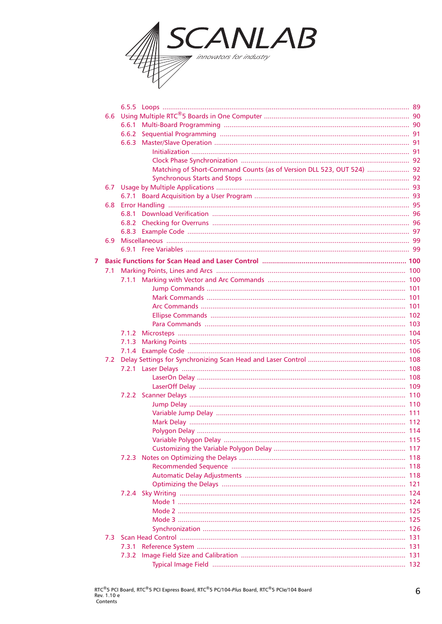
innovators for industry 6.5.5 Loops ................................................................................................................................. 89 6.6 Using Multiple RTC®5 Boards in One Computer ............................................................................ 90 6.6.1 Multi-Board Programming ................................................................................................. 90 6.6.2 Sequential Programming ................................................................................................... 91 6.6.3 Master/Slave Operation ...................................................................................................... 91 Initialization .................................................................................................................. 91 Clock Phase Synchronization ........................................................................................ 92 Matching of Short-Command Counts (as of Version DLL 523, OUT 524) ...................... 92 Synchronous Starts and Stops ...................................................................................... 92 6.7 Usage by Multiple Applications ..................................................................................................... 93 6.7.1 Board Acquisition by a User Program ................................................................................. 93 6.8 Error Handling .............................................................................................................................. 95 6.8.1 Download Verification ....................................................................................................... 96 6.8.2 Checking for Overruns ....................................................................................................... 96 6.8.3 Example Code .................................................................................................................... 97 6.9 Miscellaneous ............................................................................................................................... 99 6.9.1 Free Variables ..................................................................................................................... 99 7 Basic Functions for Scan Head and Laser Control ......................................................................... 100 7.1 Marking Points, Lines and Arcs ................................................................................................... 100 7.1.1 Marking with Vector and Arc Commands ........................................................................ 100 Jump Commands ........................................................................................................ 101 Mark Commands ........................................................................................................ 101 Arc Commands ........................................................................................................... 101 Ellipse Commands ...................................................................................................... 102 Para Commands ......................................................................................................... 103 7.1.2 Microsteps ....................................................................................................................... 104 7.1.3 Marking Points ................................................................................................................. 105 7.1.4 Example Code .................................................................................................................. 106 7.2 Delay Settings for Synchronizing Scan Head and Laser Control ................................................... 108 7.2.1 Laser Delays ..................................................................................................................... 108 LaserOn Delay ............................................................................................................. 108 LaserOff Delay ............................................................................................................ 109 7.2.2 Scanner Delays ................................................................................................................. 110 Jump Delay ................................................................................................................. 110 Variable Jump Delay ................................................................................................... 111 Mark Delay ................................................................................................................. 112 Polygon Delay ............................................................................................................. 114 Variable Polygon Delay ............................................................................................... 115 Customizing the Variable Polygon Delay ..................................................................... 117 7.2.3 Notes on Optimizing the Delays ....................................................................................... 118 Recommended Sequence ........................................................................................... 118 Automatic Delay Adjustments .................................................................................... 118 Optimizing the Delays ................................................................................................ 121 7.2.4 Sky Writing ...................................................................................................................... 124 Mode 1 ....................................................................................................................... 124 Mode 2 ....................................................................................................................... 125 Mode 3 ....................................................................................................................... 125 Synchronization .......................................................................................................... 126 7.3 Scan Head Control ...................................................................................................................... 131 7.3.1 Reference System ............................................................................................................. 131 7.3.2 Image Field Size and Calibration ...................................................................................... 131 Typical Image Field ..................................................................................................... 132 RTC®5 PCI Board, RTC®5 PCI Express Board, RTC®5 PC/104-Plus Board, RTC®5 PCIe/104 Board Rev. 1.10 e Contents 6
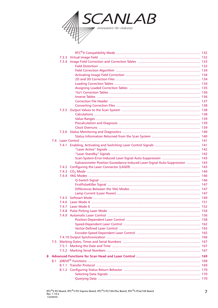
innovators for industry RTC®4 Compatibility Mode ......................................................................................... 132 7.3.3 Virtual Image Field ........................................................................................................... 132 7.3.4 Image Field Correction and Correction Tables .................................................................. 133 Field Distortion ........................................................................................................... 133 Field Correction Algorithm ......................................................................................... 134 Activating Image Field Correction ............................................................................... 134 2D and 3D Correction Files ......................................................................................... 134 Loading Correction Tables ........................................................................................... 134 Assigning Loaded Correction Tables ........................................................................... 135 1to1 Correction Tables ................................................................................................ 136 Inverse Tables ............................................................................................................. 136 Correction File Header ................................................................................................ 137 Converting Correction Files ......................................................................................... 138 7.3.5 Output Values to the Scan System ................................................................................... 138 Calculations ................................................................................................................ 138 Value Ranges .............................................................................................................. 139 Precalculation and Diagnosis ...................................................................................... 139 Clock Overruns ........................................................................................................... 139 7.3.6 Status Monitoring and Diagnostics .................................................................................. 140 Status Information Returned from the Scan System ................................................... 140 7.4 Laser Control ............................................................................................................................... 141 7.4.1 Enabling, Activating and Switching Laser Control Signals ................................................ 141 “Laser Active” Signals ................................................................................................. 142 “Laser Standby” Signals .............................................................................................. 142 Scan-System-Error-Induced Laser-Signal Auto-Suppression ........................................ 143 Galvanometer Position Exceedance-Induced Laser-Signal Auto-Suppression .............. 143 7.4.2 Configuring the Laser Connector (LASER) ........................................................................ 143 7.4.3 CO2 Mode ........................................................................................................................ 144 7.4.4 YAG Modes ...................................................................................................................... 146 Q-Switch Signal .......................................................................................................... 146 FirstPulseKiller Signal .................................................................................................. 147 Differences Between the YAG Modes .......................................................................... 147 Lamp Current (Laser Power) ........................................................................................ 147 7.4.5 Softstart Mode ................................................................................................................. 149 7.4.6 Laser Mode 4 ................................................................................................................... 151 7.4.7 Laser Mode 6 ................................................................................................................... 152 7.4.8 Pulse Picking Laser Mode ................................................................................................. 154 7.4.9 Automatic Laser Control .................................................................................................. 156 Position-Dependent Laser Control .............................................................................. 158 Speed-Dependent Laser Control ................................................................................. 162 Vector-Defined Laser Control ...................................................................................... 163 Encoder-Speed-Dependent Laser Control ................................................................... 165 7.4.10 Output Synchronization ................................................................................................... 166 7.5 Marking Dates, Times and Serial Numbers .................................................................................. 167 7.5.1 Marking the Date and Time ............................................................................................. 167 7.5.2 Marking Serial Numbers ................................................................................................... 167 8 Advanced Functions for Scan Head and Laser Control .................................................................. 169 8.1 iDRIVE® Functions ....................................................................................................................... 169 8.1.1 Transfer Protocol .............................................................................................................. 169 8.1.2 Configuring Status Return Behavior ................................................................................. 170 Selecting Data Signals ................................................................................................ 170 Querying Data ............................................................................................................ 170 RTC®5 PCI Board, RTC®5 PCI Express Board, RTC®5 PC/104-Plus Board, RTC®5 PCIe/104 Board Rev. 1.10 e Contents 7
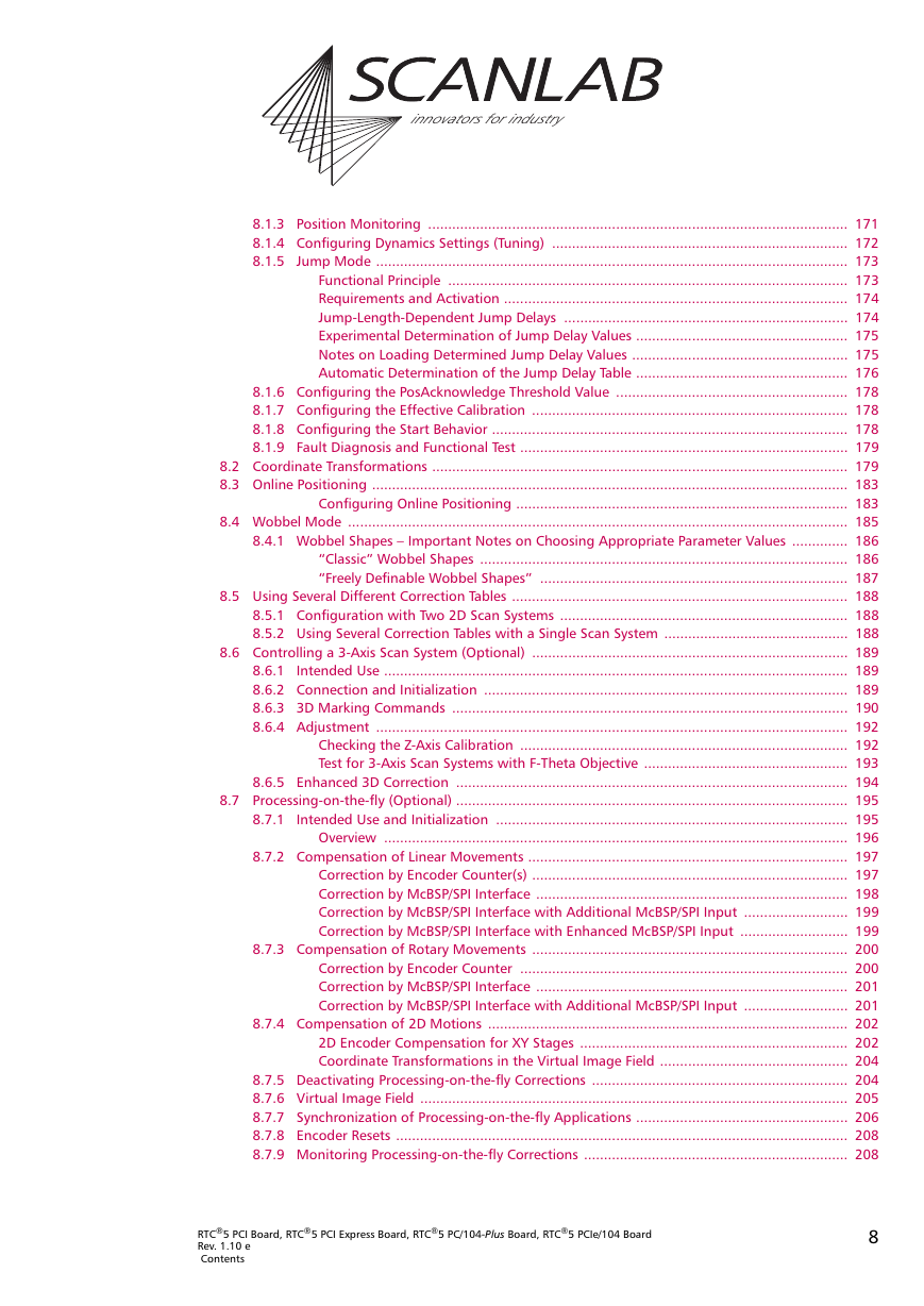
innovators for industry 8.1.3 Position Monitoring ......................................................................................................... 171 8.1.4 Configuring Dynamics Settings (Tuning) .......................................................................... 172 8.1.5 Jump Mode ...................................................................................................................... 173 Functional Principle .................................................................................................... 173 Requirements and Activation ...................................................................................... 174 Jump-Length-Dependent Jump Delays ....................................................................... 174 Experimental Determination of Jump Delay Values ..................................................... 175 Notes on Loading Determined Jump Delay Values ...................................................... 175 Automatic Determination of the Jump Delay Table ..................................................... 176 8.1.6 Configuring the PosAcknowledge Threshold Value .......................................................... 178 8.1.7 Configuring the Effective Calibration ............................................................................... 178 8.1.8 Configuring the Start Behavior ......................................................................................... 178 8.1.9 Fault Diagnosis and Functional Test .................................................................................. 179 8.2 Coordinate Transformations ........................................................................................................ 179 8.3 Online Positioning ....................................................................................................................... 183 Configuring Online Positioning ................................................................................... 183 8.4 Wobbel Mode ............................................................................................................................. 185 8.4.1 Wobbel Shapes – Important Notes on Choosing Appropriate Parameter Values .............. 186 “Classic” Wobbel Shapes ............................................................................................ 186 “Freely Definable Wobbel Shapes” ............................................................................. 187 8.5 Using Several Different Correction Tables .................................................................................... 188 8.5.1 Configuration with Two 2D Scan Systems ........................................................................ 188 8.5.2 Using Several Correction Tables with a Single Scan System .............................................. 188 8.6 Controlling a 3-Axis Scan System (Optional) ............................................................................... 189 8.6.1 Intended Use .................................................................................................................... 189 8.6.2 Connection and Initialization ........................................................................................... 189 8.6.3 3D Marking Commands ................................................................................................... 190 8.6.4 Adjustment ...................................................................................................................... 192 Checking the Z-Axis Calibration .................................................................................. 192 Test for 3-Axis Scan Systems with F-Theta Objective ................................................... 193 8.6.5 Enhanced 3D Correction .................................................................................................. 194 8.7 Processing-on-the-fly (Optional) .................................................................................................. 195 8.7.1 Intended Use and Initialization ........................................................................................ 195 Overview .................................................................................................................... 196 8.7.2 Compensation of Linear Movements ................................................................................ 197 Correction by Encoder Counter(s) ............................................................................... 197 Correction by McBSP/SPI Interface .............................................................................. 198 Correction by McBSP/SPI Interface with Additional McBSP/SPI Input .......................... 199 Correction by McBSP/SPI Interface with Enhanced McBSP/SPI Input ........................... 199 8.7.3 Compensation of Rotary Movements ............................................................................... 200 Correction by Encoder Counter .................................................................................. 200 Correction by McBSP/SPI Interface .............................................................................. 201 Correction by McBSP/SPI Interface with Additional McBSP/SPI Input .......................... 201 8.7.4 Compensation of 2D Motions .......................................................................................... 202 2D Encoder Compensation for XY Stages ................................................................... 202 Coordinate Transformations in the Virtual Image Field ............................................... 204 8.7.5 Deactivating Processing-on-the-fly Corrections ................................................................ 204 8.7.6 Virtual Image Field ........................................................................................................... 205 8.7.7 Synchronization of Processing-on-the-fly Applications ..................................................... 206 8.7.8 Encoder Resets ................................................................................................................. 208 8.7.9 Monitoring Processing-on-the-fly Corrections .................................................................. 208 RTC®5 PCI Board, RTC®5 PCI Express Board, RTC®5 PC/104-Plus Board, RTC®5 PCIe/104 Board Rev. 1.10 e Contents 8
分享到:
收藏