logo资料库

YRC1000MICRO高速以太网.pdf

第1页 / 共292页
第2页 / 共292页
第3页 / 共292页
第4页 / 共292页
第5页 / 共292页
第6页 / 共292页
第7页 / 共292页
第8页 / 共292页
资料共292页,剩余部分请下载后查看
1 Outline
1.1 Outline
1.2 Command Remote Setting for YRC1000
1.2.1 Remote Mode and Local Mode
1.2.2 Switching the Function by Command Remote Setting
1.2.3 Command Remote Setting Method
1.2.4 Command Remote State Displayed Window
1.3 Ethernet Cable Connections
1.4 Notes When Loading the Data
2 LAN Interface Setting and Network Communication Confirmation
2.1 LAN Interface Setting
2.1.1 Setting procedure
2.1.2 LAN Interface Setting Item
2.1.2.1 Host Setting
2.1.2.2 Setting the Domain
2.1.2.3 IP Address (LAN2)
2.1.2.4 IP Address (LAN3)
2.1.2.5 Default Gateway
2.1.2.6 Static Route (LAN2)
2.1.2.7 Static Route (LAN3)
2.1.2.8 DNS Setting
2.1.2.9 SNTP Setting
2.2 Daylight Saving Time Setting
2.3 LAN Interface Setting Confirmation
2.3.1 LAN Interface Setting Confirmation Method
2.3.2 Information Displayed on the Network Service Window
2.3.2.1 Host Setting
2.3.2.2 Domain Setting
2.3.2.3 IP Address (LAN2)
2.3.2.4 IP ADDRESS (LAN3)
2.3.2.5 Default Gateway
2.3.2.6 Static Route (LAN2)
2.3.2.7 Static Route (LAN3)
2.3.2.8 DNS Setting
2.3.2.9 SNTP Setting
2.4 Network Communication Confirmation
2.4.1 Network Communication Confirmation from Windows PC
2.4.2 Network Communication Confirmation from the YRC1000
3 High-Speed Ethernet Server Function
3.1 Outline
3.1.1 System Configuration
3.1.2 Communication Target
3.1.3 Restriction
3.2 Setting
3.2.1 Basic Setting
3.2.2 Batch Data Back-up Function Setting
3.2.3 Command Remote Setting
3.3 Communication Method
3.3.1 Packet Format
3.3.2 Transmission Procedure
3.3.2.1 Robot Control/Status Reading
3.3.2.2 Robot Control/Data Writing to Register
3.3.2.3 File Control (File Saving)
3.3.2.4 File Control (File Loading)
3.3.2.5 File Control (File List)
3.3.2.6 File Control (Deleting of file)
3.3.3 Robot Control Command
3.3.3.1 Alarm Data Reading Command
3.3.3.2 Alarm History Reading Command
3.3.3.3 Status Information Reading Command
3.3.3.4 Executing Job Information Reading Command
3.3.3.5 Axis Configuration Information Reading Command
3.3.3.6 Robot Position Data Reading Command
3.3.3.7 Position Error Reading Command
3.3.3.8 Torque Data Reading Data
3.3.3.9 I/O Data Reading / Writing Command
3.3.3.10 Register Data Reading / Writing Command
3.3.3.11 Byte Variable (B) Reading / Writing Command
3.3.3.12 Integer Type Variable (I) Reading / Writing Command
3.3.3.13 Double Precision Integer Type Variable (D) Reading / Writing Command
3.3.3.14 Real Type Variable (R) Reading / Writing Command
3.3.3.15 16 Byte Character Type Variable (S) Reading Writing Command
3.3.3.16 Robot Position Type Variable (P) Reading / Writing Command
3.3.3.17 Base Position Type Variable (BP) Reading / Writing Command
3.3.3.18 External Axis Type Variable (EX) Reading / Writing Command
3.3.3.19 Alarm Reset / Error Cancel Command
3.3.3.20 Hold / Servo On/off Command
3.3.3.21 Step / Cycle / Auto Switching Command
3.3.3.22 Character String Display Command To The Programming Pendant
3.3.3.23 Start-up (Job Start) Command
3.3.3.24 Job Select Command
3.3.3.25 Management Time Acquiring Command
3.3.3.26 System Information Acquiring Command
3.3.3.27 Plural I/O Data Reading / Writing Command
3.3.3.28 Plural Register Data Reading / Writing Command
3.3.3.29 Plural Byte Type Variable (B) Reading / Writing Command
3.3.3.30 Plural Integer Type Variable (I) Reading / Writing Command
3.3.3.31 Plural Double Precision Integer Type Variable (D) Reading / Writing Command
3.3.3.32 Plural Real Type Variable (R) Reading / Writing Command
3.3.3.33 Plural 16 Byte Character Type Variable (S) Reading / Writing Command
3.3.3.34 Plural Robot Position Type Variable (P) Reading / Writing Command
3.3.3.35 Plural Base Position Type Variable (BP) Reading / Writing Command
3.3.3.36 Plural Station Type Variable (EX) Reading / Writing Command
3.3.3.37 Alarm Data Reading Command (for Applying the Sub Code Character String)
3.3.3.38 Alarm History Reading Command (for Applying the Sub Code Character String)
3.3.3.39 Move instruction command (Type Cartesian Coordinate)
3.3.3.40 Move Instruction Command (Type Pulse)
3.3.3.41 32 Byte Character Type Variable (S) Reading Writing Command
3.3.3.42 Plural 32 Byte Character Type Variable (S) Reading / Writing Command
3.3.4 File Control Command
3.3.4.1 File Deleting Command
3.3.4.2 File Loading Command
3.3.4.3 File Saving Command
3.3.4.4 File List Acquiring Command
3.3.4.5 File Saving Command (Batch Data Backup)
3.4 Response Code
3.4.1 Status Code
3.4.2 Added Status Code
3.5 Troubleshooting
3.5.1 Network Communication Confirmation
3.5.2 Communication Setting Confirmation for Firewall and Security Software
3.5.3 Error Log Confirmation of High-speed Ethernet Server Communication
4 FTP Server Function
4.1 Outline
4.1.1 System Configuration
4.1.2 Communication Target
4.1.3 Function Mode
4.1.4 CMOS Saving Function via FTP
4.1.5 Restriction
4.2 Setting
4.2.1 Enabling Setting for the FTP Function
4.2.2 Enabling the CMOS Saving Function via FTP
4.2.3 Command Remote Setting
4.3 Specification
4.3.1 Account
4.4 Communication Method
4.4.1 Example of Communication Procedure in Normal Operation Mode (When Using the Windows 7 Command Prompt)
4.4.2 Example of Communication Procedure in Expand Mode (When Using FileZilla)
4.4.3 Saving CMOS Data by Using CMOS Saving Function via FTP
4.5 Troubleshooting
4.5.1 Network Communication Confirmation
4.5.2 Confirming the Communication Setting for Firewall and Security Software
4.5.3 Confirming the Function Mode
5 DCI Function
5.1 Outline
5.1.1 System Configuration
5.1.2 Communication Target
5.2 Setting
5.2.1 Communication Target Setting
5.2.2 Command Remote OFF Setting
5.3 Preparation at the YRC1000 Side
5.3.1 Command for Job Transmission
5.3.1.1 LOADJ
5.3.1.2 SAVEJ
5.3.1.3 DELETEJ
5.3.1.4 SWAIT
5.3.2 Command for Variable Transmission
5.3.2.1 LOADV
5.3.2.2 SAVEV
5.3.3 Registering DCI Command
5.3.4 Concurrent Task from Multiple Job
5.3.5 DCI Parallel Execution
5.3.5.1 Parallel Execution Using NWAIT
5.3.5.2 Parallel Execution Using PSTART (Optional)
5.3.6 Axis Data Transmission Format
5.4 Preparation at the PC Side
5.5 Executing the DCI Function
5.6 Alarm Code
5.7 Troubleshooting
5.7.1 Network Communication Confirmation
5.7.2 Communication Setting Confirmation for Firewall and Security Software
5.7.3 Confirming the Operation of the PC-side Application
5.7.4 Confirming That the Remote Setting is OFF
6 FTP Client Function
6.1 Outline
6.1.1 System Configuration
6.1.2 Communication Target
6.1.3 Restriction
6.2 Preparation at the PC Side
6.3 YRC1000-side Setting and Operation
6.3.1 Enabling Setting for the FTP Function
6.3.2 Setting for the FTP Connection Condition
6.3.3 Selecting the FTP Function
6.3.4 Save
6.3.4.1 Saving a Job
6.3.4.2 Saving Files Except for Job
6.3.5 Load
6.3.5.1 Loading a Job
6.3.5.2 Loading File Except for Job
6.3.6 Verification
6.3.6.1 Verifying a Job
6.3.6.2 Verifying File Except for Job
6.3.7 Selecting Job and Data File
6.4 Troubleshooting
6.4.1 Network Communication Confirmation
6.4.2 Communication Setting Confirmation for Firewall and Security Software
6.4.3 Confirming the FTP Server Operation
6.4.4 Confirming That the Remote Setting is OFF
7 Internal Data Browsing Function by Using a Web Browser
7.1 Outline
7.1.1 System Configuration
7.1.2 Communication Target
7.1.3 Restriction
7.2 Setting Method
7.2.1 Function Setting
7.2.2 Command Remote Setting
7.3 Transmission Procedure Example
7.4 Troubleshooting
7.4.1 Network Communication Confirmation
7.4.2 Communication Setting Confirmation for Firewall and Security Software
8 Ethernet Server Function
8.1 Outline
8.1.1 System Configuration
8.1.2 Communication Target
8.1.3 General Information for When Using the Ethernet Server Function
8.1.4 Restriction
8.2 Setting
8.2.1 Function Setting
8.2.2 Command Remote Setting
8.3 Communication Method
8.3.1 Transmission procedure
8.3.1.1 Socket Connection
8.3.1.2 START Request
8.3.1.3 Response to START Request
8.3.1.4 Command
8.3.1.5 Response to Command
8.3.1.6 Command Data
8.3.1.7 Answer
8.3.1.8 Closing of a Socket
8.3.2 Command Detail
8.3.2.1 Status Read Function
8.3.2.2 System Control Function
8.3.2.3 I/O Read/Write Function
8.3.3 Transmission Example
8.3.3.1 Read-Out of Status for Mode, Cycle, etc
8.3.3.2 Read-Out of I/O Signals for the YRC1000
8.3.3.3 Write-In of I/O Signals for the YRC1000
8.3.3.4 Continuous Execution of Multiple Command
8.4 Troubleshooting
8.4.1 Network Communication Confirmation
8.4.2 Communication Setting Confirmation for Firewall and Security Software
8.4.3 Confirming the connection of the Ethernet Server Function
9 Host Control Function
9.1 Outline
9.1.1 System Configuration
9.1.2 Communication Target
9.1.3 General Information When Using the Host Control Function
9.1.4 Restriction
9.2 Setting
9.2.1 Command Remote Setting
9.3 Transmission Procedure
9.3.1 File Data Transmission Function
9.3.2 Manipulator Control Function
9.4 Troubleshooting
9.4.1 Network Communication Confirmation
9.4.2 Communication Setting Confirmation of Firewall and Security Software
10 Standalone Function
10.1 Outline
10.1.1 System Configuration
10.1.2 Communication Target
10.2 Setting
10.2.1 Communication Target Setting
10.2.2 Command Remote to OFF Setting
10.3 Preparation at the PC Side
10.4 Executing the Standalone Function
10.4.1 Selecting the Standalone Function
10.4.2 Save
10.4.2.1 Save Job
10.4.2.2 Save a File Other Than Job
10.4.3 Load
10.4.3.1 Load the Job
10.4.3.2 Load a File Other Than Job
10.4.4 Verification
10.4.4.1 Verifying the Job
10.4.4.2 Verifying the File Other Than the Job
10.4.5 Selection Mode of the Job
10.4.5.1 Single Selection Mode
10.4.5.2 Related Selection Mode
10.4.5.3 Switching the Selection Mode
10.4.6 Selecting a Job or Data File
10.4.6.1 Individual Selection
10.4.6.2 SELECT ALL
10.5 Troubleshooting
10.5.1 Network Communication Confirmation
10.5.2 Communication Setting Confirmation for Firewall and Security Software
10.5.3 Confirming the Operation of the PC-side Application
10.5.4 Confirming That the Remote Setting is OFF
11 Related Information
11.1 General Information About the Host Control System Function
11.1.1 List of Interlock for Command of Host Control Function
11.1.2 Command that Handle Axis Data
11.1.3 Response to MOV-type Command
11.1.4 Command for Multi-control Group and Independent Control Function
11.1.4.1 Command for Multi-control Group
11.1.4.2 Command for Independent Control Function
11.1.5 Interpreter Message
11.1.6 Alarm Code
11.2 Related Parameter
11.3 Communication Specification
11.4 Recommended Cable and Switching Hub
YRC1000 OPTIONS INSTRUCTIONS FOR ETHERNET FUNCTION Upon receipt of the product and prior to initial operation, read these instructions thoroughly, and retain for future reference. MOTOMAN INSTRUCTIONS MOTOMAN- INSTRUCTIONS YRC1000 INSTRUCTIONS YRC1000 OPERATOR’S MANUAL (GENERAL) (SUBJECT SPECIFIC) YRC1000 MAINTENANCE MANUAL YRC1000 ALARM CODES (MAJOR ALARMS) (MINOR ALARMS) The YRC1000 operator’s manual above corresponds to specific usage. Be sure to use the appropriate manual. The YRC1000 operator’s manual above consists of “GENERAL” and “SUBJECT SPECIFIC”. The YRC1000 alarm codes above consists of “MAJOR ALARMS” and “MINOR ALARMS”. 178942-1CD 2 MANUAL NO. HW1483358 2 1/292
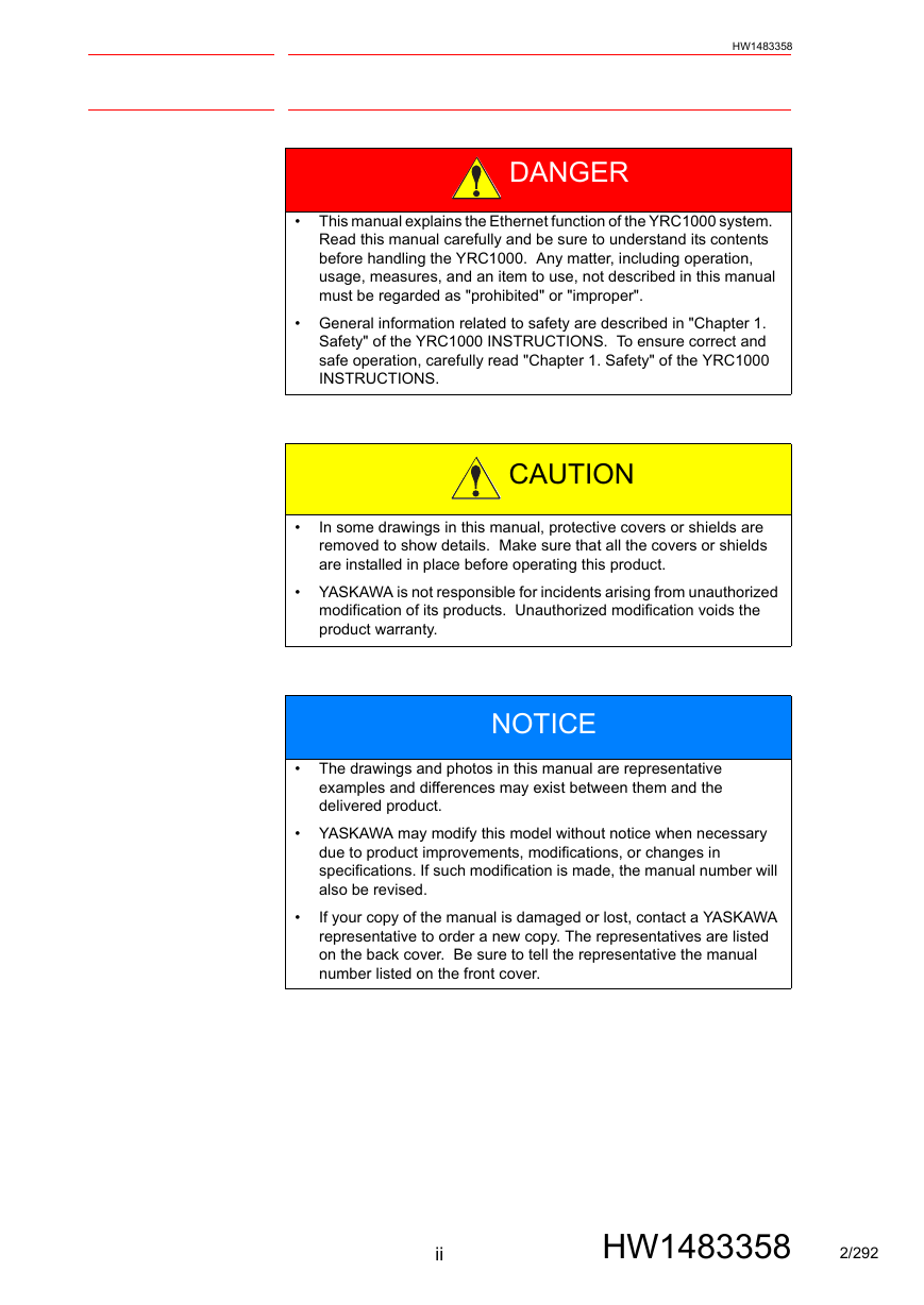
HW1483358 DANGER • This manual explains the Ethernet function of the YRC1000 system. Read this manual carefully and be sure to understand its contents before handling the YRC1000. Any matter, including operation, usage, measures, and an item to use, not described in this manual must be regarded as "prohibited" or "improper". • General information related to safety are described in "Chapter 1. Safety" of the YRC1000 INSTRUCTIONS. To ensure correct and safe operation, carefully read "Chapter 1. Safety" of the YRC1000 INSTRUCTIONS. CAUTION • In some drawings in this manual, protective covers or shields are removed to show details. Make sure that all the covers or shields are installed in place before operating this product. • YASKAWA is not responsible for incidents arising from unauthorized modification of its products. Unauthorized modification voids the product warranty. NOTICE • The drawings and photos in this manual are representative examples and differences may exist between them and the delivered product. • YASKAWA may modify this model without notice when necessary due to product improvements, modifications, or changes in specifications. If such modification is made, the manual number will also be revised. If your copy of the manual is damaged or lost, contact a YASKAWA representative to order a new copy. The representatives are listed on the back cover. Be sure to tell the representative the manual number listed on the front cover. • ii HW1483358 2/292
HW1483358 NOTES FOR SAFE OPERATION Read this manual carefully before installation, operation, maintenance, or inspection of the YRC1000. In this manual, the Notes for Safe Operation are classified as “DANGER”, “WARNING”, “CAUTION”, or “NOTICE”. DANGER WARNING CAUTION NOTICE Indicates an imminently hazardous situation which, if not avoided, will result in death or serious injury. Safety Signs identified by the signal word DANGER should be used sparingly and only for those situations presenting the most serious hazards. Indicates a potentially hazardous situation which, if not avoided, will result in death or serious injury. Hazards identified by the signal word WARNING present a lesser degree of risk of injury or death than those identified by the signal word DANGER. Indicates a hazardous situation, which if not avoided, could result in minor or moderate injury. It may also be used without the safety alert symbol as an alternative to “NOTICE”. NOTICE is the preferred signal word to address practices not related to personal injury. The safety alert symbol should not be used with this signal word. As an alternative to “NOTICE”, the word “CAUTION” without the safety alert symbol may be used to indicate a message not related to personal injury. Even items described as “CAUTION” may result in a serious accident in some situations. At any rate, be sure to follow these important items. NOTE To ensure safe and efficient operation at all times, be sure to follow all instructions, even if not designated as “DAN- GER”, “WARNING” and “CAUTION". iii HW1483358 3/292
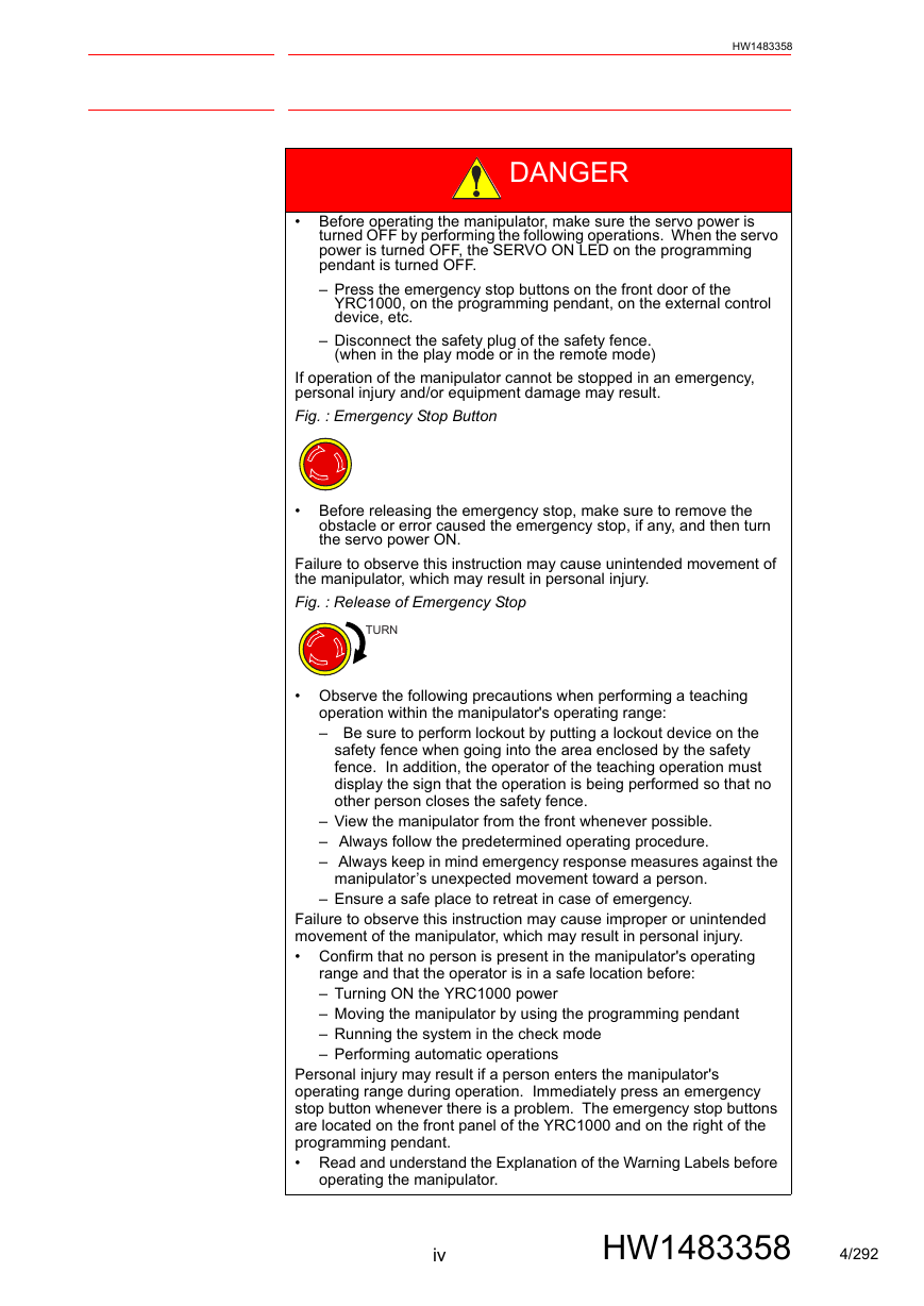
HW1483358 DANGER • Before operating the manipulator, make sure the servo power is turned OFF by performing the following operations. When the servo power is turned OFF, the SERVO ON LED on the programming pendant is turned OFF. – Press the emergency stop buttons on the front door of the YRC1000, on the programming pendant, on the external control device, etc. – Disconnect the safety plug of the safety fence. (when in the play mode or in the remote mode) If operation of the manipulator cannot be stopped in an emergency, personal injury and/or equipment damage may result. Fig. : Emergency Stop Button • Before releasing the emergency stop, make sure to remove the obstacle or error caused the emergency stop, if any, and then turn the servo power ON. Failure to observe this instruction may cause unintended movement of the manipulator, which may result in personal injury. Fig. : Release of Emergency Stop TURN • Observe the following precautions when performing a teaching operation within the manipulator's operating range: – Be sure to perform lockout by putting a lockout device on the safety fence when going into the area enclosed by the safety fence. In addition, the operator of the teaching operation must display the sign that the operation is being performed so that no other person closes the safety fence. – View the manipulator from the front whenever possible. – Always follow the predetermined operating procedure. – Always keep in mind emergency response measures against the manipulator’s unexpected movement toward a person. – Ensure a safe place to retreat in case of emergency. Failure to observe this instruction may cause improper or unintended movement of the manipulator, which may result in personal injury. • Confirm that no person is present in the manipulator's operating range and that the operator is in a safe location before: – Turning ON the YRC1000 power – Moving the manipulator by using the programming pendant – Running the system in the check mode – Performing automatic operations Personal injury may result if a person enters the manipulator's operating range during operation. Immediately press an emergency stop button whenever there is a problem. The emergency stop buttons are located on the front panel of the YRC1000 and on the right of the programming pendant. • Read and understand the Explanation of the Warning Labels before operating the manipulator. iv HW1483358 4/292
HW1483358 WARNING • Perform the following inspection procedures prior to conducting manipulator teaching. If there is any problem, immediately take necessary steps to solve it, such as maintenance and repair. – Check for a problem in manipulator movement. – Check for damage to insulation and sheathing of external wires. • Always return the programming pendant to the hook on the YRC1000 cabinet after use. If the programming pendant is left unattended on the manipulator, on a fixture, or on the floor, etc., the Enable Switch may be activated due to surface irregularities of where it is left, and the servo power may be turned ON. In addition, in case the operation of the manipulator starts, the manipulator or the tool may hit the programming pendant left unattended, which may result in personal injury and/or equipment damage. Definition of Terms Used Often in This Manual The MOTOMAN is the YASKAWA industrial robot product. The MOTOMAN usually consists of the manipulator, the controller, the programming pendant, and supply cables. In this manual, the equipment is designated as follows. Equipment YRC1000 controller YRC1000 programming pendant Cable between the manipulator and the controller Manual Designation YRC1000 Programming pendant Manipulator cable v HW1483358 5/292
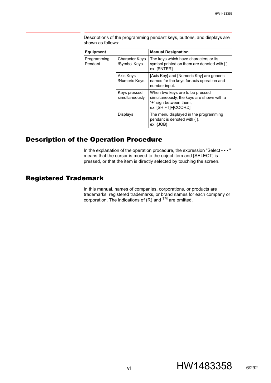
HW1483358 Descriptions of the programming pendant keys, buttons, and displays are shown as follows: Equipment Programming Pendant Character Keys /Symbol Keys Axis Keys /Numeric Keys Keys pressed simultaneously Displays Manual Designation The keys which have characters or its symbol printed on them are denoted with [ ]. ex. [ENTER] [Axis Key] and [Numeric Key] are generic names for the keys for axis operation and number input. When two keys are to be pressed simultaneously, the keys are shown with a “+” sign between them, ex. [SHIFT]+[COORD] The menu displayed in the programming pendant is denoted with { }. ex. {JOB} Description of the Operation Procedure In the explanation of the operation procedure, the expression "Select • • • " means that the cursor is moved to the object item and [SELECT] is pressed, or that the item is directly selected by touching the screen. Registered Trademark In this manual, names of companies, corporations, or products are trademarks, registered trademarks, or brand names for each company or corporation. The indications of (R) and TM are omitted. vi HW1483358 6/292
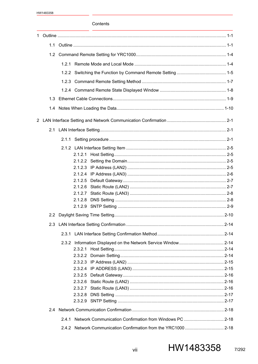
HW1483358 Contents 1 Outline ............................................................................................................................................ 1-1 1.1 Outline ............................................................................................................................... 1-1 1.2 Command Remote Setting for YRC1000........................................................................... 1-4 1.2.1 Remote Mode and Local Mode ............................................................................ 1-4 1.2.2 Switching the Function by Command Remote Setting ......................................... 1-5 1.2.3 Command Remote Setting Method ...................................................................... 1-7 1.2.4 Command Remote State Displayed Window ....................................................... 1-8 1.3 Ethernet Cable Connections.............................................................................................. 1-9 1.4 Notes When Loading the Data......................................................................................... 1-10 2 LAN Interface Setting and Network Communication Confirmation ................................................. 2-1 2.1 LAN Interface Setting......................................................................................................... 2-1 2.1.1 Setting procedure ................................................................................................. 2-1 2.1.2 LAN Interface Setting Item ................................................................................... 2-5 2.1.2.1 Host Setting............................................................................................. 2-5 2.1.2.2 Setting the Domain.................................................................................. 2-5 2.1.2.3 IP Address (LAN2) .................................................................................. 2-5 2.1.2.4 IP Address (LAN3) .................................................................................. 2-6 2.1.2.5 Default Gateway...................................................................................... 2-7 2.1.2.6 Static Route (LAN2) ................................................................................ 2-7 2.1.2.7 Static Route (LAN3) ................................................................................ 2-8 2.1.2.8 DNS Setting ............................................................................................ 2-8 2.1.2.9 SNTP Setting .......................................................................................... 2-9 2.2 Daylight Saving Time Setting........................................................................................... 2-10 2.3 LAN Interface Setting Confirmation ................................................................................. 2-14 2.3.1 LAN Interface Setting Confirmation Method....................................................... 2-14 2.3.2 Information Displayed on the Network Service Window..................................... 2-14 2.3.2.1 Host Setting........................................................................................... 2-14 2.3.2.2 Domain Setting...................................................................................... 2-14 2.3.2.3 IP Address (LAN2) ................................................................................ 2-15 2.3.2.4 IP ADDRESS (LAN3) ............................................................................ 2-15 2.3.2.5 Default Gateway.................................................................................... 2-16 2.3.2.6 Static Route (LAN2) .............................................................................. 2-16 2.3.2.7 Static Route (LAN3) .............................................................................. 2-16 2.3.2.8 DNS Setting .......................................................................................... 2-17 2.3.2.9 SNTP Setting ........................................................................................ 2-17 2.4 Network Communication Confirmation ............................................................................ 2-18 2.4.1 Network Communication Confirmation from Windows PC ................................. 2-18 2.4.2 Network Communication Confirmation from the YRC1000 ................................ 2-18 vii HW1483358 7/292
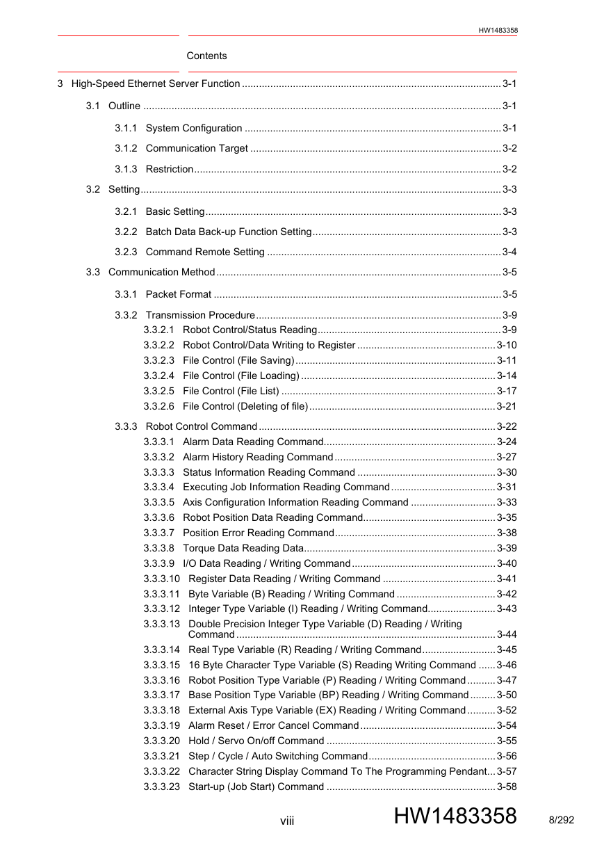
Contents HW1483358 3 High-Speed Ethernet Server Function ............................................................................................3-1 3.1 Outline ...............................................................................................................................3-1 3.1.1 System Configuration ...........................................................................................3-1 3.1.2 Communication Target .........................................................................................3-2 3.1.3 Restriction.............................................................................................................3-2 3.2 Setting................................................................................................................................3-3 3.2.1 Basic Setting.........................................................................................................3-3 3.2.2 Batch Data Back-up Function Setting...................................................................3-3 3.2.3 Command Remote Setting ...................................................................................3-4 3.3 Communication Method.....................................................................................................3-5 3.3.1 Packet Format ......................................................................................................3-5 3.3.2 Transmission Procedure.......................................................................................3-9 3.3.2.1 Robot Control/Status Reading.................................................................3-9 3.3.2.2 Robot Control/Data Writing to Register .................................................3-10 3.3.2.3 File Control (File Saving).......................................................................3-11 3.3.2.4 File Control (File Loading) .....................................................................3-14 3.3.2.5 File Control (File List) ............................................................................3-17 3.3.2.6 File Control (Deleting of file)..................................................................3-21 3.3.3 Robot Control Command....................................................................................3-22 3.3.3.1 Alarm Data Reading Command.............................................................3-24 3.3.3.2 Alarm History Reading Command.........................................................3-27 3.3.3.3 Status Information Reading Command .................................................3-30 3.3.3.4 Executing Job Information Reading Command.....................................3-31 3.3.3.5 Axis Configuration Information Reading Command ..............................3-33 3.3.3.6 Robot Position Data Reading Command...............................................3-35 3.3.3.7 Position Error Reading Command.........................................................3-38 3.3.3.8 Torque Data Reading Data....................................................................3-39 3.3.3.9 I/O Data Reading / Writing Command...................................................3-40 3.3.3.10 Register Data Reading / Writing Command ........................................3-41 3.3.3.11 Byte Variable (B) Reading / Writing Command ...................................3-42 3.3.3.12 Integer Type Variable (I) Reading / Writing Command........................3-43 3.3.3.13 Double Precision Integer Type Variable (D) Reading / Writing Command ............................................................................................3-44 3.3.3.14 Real Type Variable (R) Reading / Writing Command..........................3-45 3.3.3.15 16 Byte Character Type Variable (S) Reading Writing Command ......3-46 3.3.3.16 Robot Position Type Variable (P) Reading / Writing Command..........3-47 3.3.3.17 Base Position Type Variable (BP) Reading / Writing Command.........3-50 3.3.3.18 External Axis Type Variable (EX) Reading / Writing Command..........3-52 3.3.3.19 Alarm Reset / Error Cancel Command................................................3-54 3.3.3.20 Hold / Servo On/off Command ............................................................3-55 3.3.3.21 Step / Cycle / Auto Switching Command.............................................3-56 3.3.3.22 Character String Display Command To The Programming Pendant...3-57 3.3.3.23 Start-up (Job Start) Command ............................................................3-58 viii HW1483358 8/292
分享到:
收藏