1 Introduction
1.1 Product Description
1.1.1 MTi-G – miniature GPS/INS
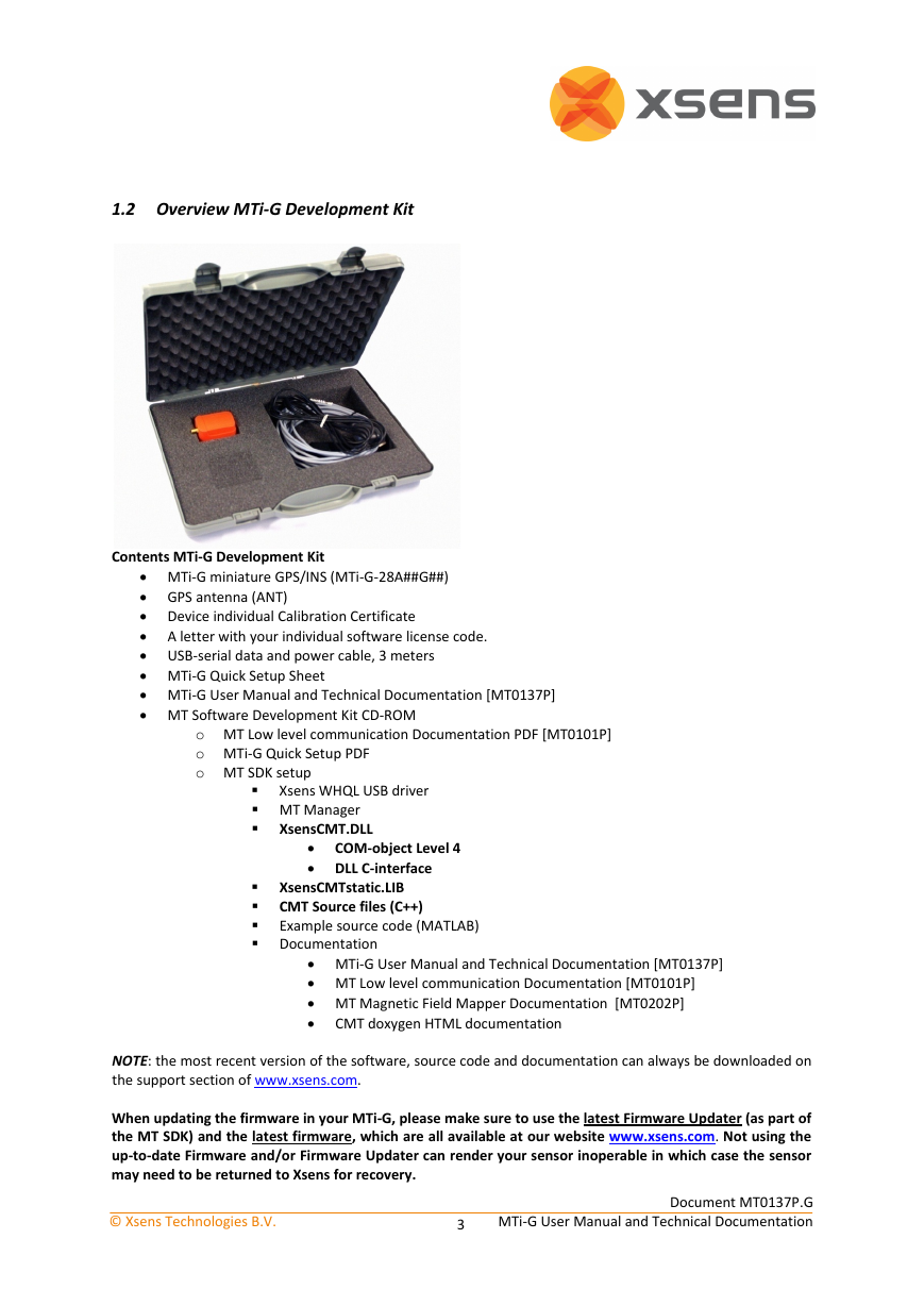
1.2 Overview MTi-G Development Kit
Quick start - Different ways of interfacing to the MTi-G
1.3.1 Getting Started with the MT Manager
1.3.2 Interface through COM-object API
1.3.3 Interface through DLL API
1.3.4 Direct low-level communication with MTi-G
2 MTi-G System Overview
2.1 Architecture Overview
2.2 Xsens Kalman Filter for MTi-G
2.2.1 Dead reckoning using inertial sensors
2.2.2 Position and orientation correction using GPS
2.2.3 Altitude correction using a static pressure sensor
2.2.4 Heading observability
2.2.5 Handling of GPS Outages
2.2.6 XKF Scenarios
2.3 Limitations
3 Installation and Operation
3.1 Installation
3.1.1 Hardware Setup
3.1.2 First use
3.2 Normal operating procedure
3.3 GPS antenna positioning with respect to MTi-G
3.4 Placement considerations
3.4.1 Transient accelerations during GPS outages
3.4.2 Vibrations
3.4.3 Magnetic materials and magnets
3.4.4 Atmospheric pressure
3.5 RF interference and reflections and GPS antenna placement
3.5.1 RF interference
3.5.2 Reflections
4 Output Specification
4.1 Co-ordinate system definitions
4.1.1 Default MTi-G co-ordinate system definitions
4.1.2 Default MTi-G body fixed co-ordinate system
4.1.3 Locally tangent plane Euclidian linearized coordinate system - LTP
4.1.4 Default definition of G and S
4.1.5 True North vs. Magnetic North
4.1.6 North East Down optional MTi-G co-ordinate system definitions
4.1.7 Linearization errors and relation WGS84 and LTP
4.2 Performance specification
4.3 Orientation output modes
4.3.1 Quaternion orientation output mode
4.3.2 Euler angles orientation output mode
4.3.3 Rotation Matrix orientation Output Mode
4.4 Position and Velocity Output Mode
4.5 Status Byte (BIT)
4.6 Calibrated data performance specification
Calibrated data output mode
4.7.1 Physical sensor model
4.7.2 Calibrated inertial and magnetic data output mode
4.8 RAW Data Output Modes
4.8.1 RAW inertial sensor data Output Mode
4.8.2 GPS PVT data Output Mode
4.9 Reset of output or reference co-ordinate systems
4.9.1 Output with respect to non-default coordinate frames
4.9.2 Arbitrary Object alignment
4.9.3 Object reset
4.10 Timestamp output
4.11 MTi-G clock bias estimation to UTC
4.12 Test and Calibration Certificate
5 MT communication protocol
5.1 Introduction
5.2 MT Device States
5.3 MT Messages
5.3.1 Message structure
5.3.2 Message usage
5.3.3 Common messages
5.4 Communication Timing
5.5 Triggering & synchronization
5.5.1 MTi-G triggers external devices
5.6 Internal clock accuracy
5.7 Default Serial Connection Settings
5.7.1 General definitions for binary data
6 Physical Specifications
6.1 Physical sensor overview
6.2 Physical properties overview
6.2.1 MTi-G physical specifications overview
6.3 Power supply
6.4 Physical interface specifications
6.4.1 USB-serial data and power cables overview
6.4.2 Pin and wire color definitions MTi-G-28A##G## (MTi-G RS-232, standard version)
6.4.3 Additional interface specifications
6.5 Housing mechanical specifications
6.5.1 Dimensions MTi-G
6.6 Physical location of Origin of the MTi-G
6.7 GPS antenna electrical and mechanical specifications
6.7.1 Not using the default Wi-sys WS3910 antenna
7 Important notices
7.1 Environmental Operating Conditions
7.2 FCC specific operating instructions
7.3 Safety instructions
Absolute maximum ratings
7.5 Maintenance
7.5.1 Cleaning
7.6 Warranty and liability
7.7 CE Declaration of Conformity for the MT devices
7.8 FCC Declaration of Conformity for the MT devices
7.9 CE Declaration of Conformity for the USB converters
7.10 FCC Declaration of Conformity for the USB converters
7.11 Power supply considerations for conductive HF emission
7.12 Customer Support


 2023年江西萍乡中考道德与法治真题及答案.doc
 2012年重庆南川中考生物真题及答案.doc
 2013年江西师范大学地理学综合及文艺理论基础考研真题.doc
 2020年四川甘孜小升初语文真题及答案I卷.doc
 2020年注册岩土工程师专业基础考试真题及答案.doc
 2023-2024学年福建省厦门市九年级上学期数学月考试题及答案.doc
 2021-2022学年辽宁省沈阳市大东区九年级上学期语文期末试题及答案.doc
 2022-2023学年北京东城区初三第一学期物理期末试卷及答案.doc
 2018上半年江西教师资格初中地理学科知识与教学能力真题及答案.doc
 2012年河北国家公务员申论考试真题及答案-省级.doc
 2020-2021学年江苏省扬州市江都区邵樊片九年级上学期数学第一次质量检测试题及答案.doc
 2022下半年黑龙江教师资格证中学综合素质真题及答案.doc