Transportation Systems
Data Sheet
MVB-Controller ASIC
MVBCS1
Created:
Changed:
Version:
Number of pages:
2001-10-05
-
1.00
150
©
The passing on, as well as the copying, distributiogn and/or adaptation of this document, exploitation gand communication of
its contents without expressed authorization is proghibited. Contravention entails liability for the pagyment of damages. All
rights reserved in the event of a patent, utility mgodel or ornamental design registration.
Copyright © Siemens AG 1999-2001 All Rights Reserve d
�
REVISION HISTORY
Version
1.00
Date
Description
Remark
2001-10-05
Release 1.00
Transportation Systems
DISCLAIMER
Siemens AG makes no warranty of any kind with regardG to this material, including, but not limited to, the
implied warranties of merchantability and fitness foGr a particular purpose. The company named above
assumes no responsibility for any errors that may appGear in this document. No liability is assumed arising
out of application or use of this product described herGein.
The company named above reserves the right to make changesG to this product herein to improve reliability,
functionality or design. The information in this documeGnt and the product described by this document is
subject to change without prior notice.
QUALITY ASSURANCE
The quality system of Siemens bases on the "Principles oGf Siemens Quality Management" and fulfills the
claims of the DIN EN ISO 9001 standard.
The conformity to the standard is examined by an externGal corporation for certification regularly.
Data Sheet
MVBCS1
Siemens AG
TS GT E2
2001-10-05
Page
2
of
150
Copyright (C) Siemens AG 1999-2001 All Rights Reserved
DSS1_100.doc
�
TABLE OF CONTENTS
1
INTRODUCTION ....................................................................................................................................................6
Transportation Systems
1.1
1.2
1.3
1.4
1.5
ABSTRACT...................................................D...................................................D.........................
INTENDED AUDIENCE ...................................................D...................................................D.........................
SCOPE ...................................................D...................................................D.........................
DEFINITIONS AND ABBREVIATIONS...................................................D...................................................D..............6
CONVENTIONS...................................................D...................................................D.........................
..........................6
.........6
................................6
..................10
1.5.1
1.5.2
Bit and Byte Order ...................................................d...................................................d..
Stylistics...................................................d...................................................d..........
.........................10
..................................11
LIST OF ILLUSTRATIONS...................................................D...................................................D.........................
....11
LIST OF TABLES...................................................D...................................................D.........................
................12
DOCUMENT STRUCTURE ...................................................D...................................................D.........................
..13
1.6
1.7
1.8
2 MVBCS1 OVERVIEW..........................................................................................................................................14
INCLUDED CHIP FEATURES...................................................D...................................................D........................14
DEVICE INTERFACE SYMBOL...................................................D...................................................D.....................15
SYSTEMS SUPPORTED...................................................D...................................................D.........................
2.1
2.2
2.3
.......16
2.4 MVBCS1 VERSUS MVBC01 ...................................................D...................................................D...................
.17
2.5
.......17
INPUT / OUTPUT PINS ...................................................D...................................................D.........................
2.5.1
2.5.2
Pinout Diagram...................................................d...................................................d......
Pin Description...................................................d...................................................d.....
..........................17
............................18
2.6
2.7
PHYSICAL LAYER INTERFACE TO THE MVB...................................................D.................................................20
PHYSICAL INTERFACE TO TRAFFIC MEMORY AND CPU ...................................................D...............................22
2.7.1
2.7.2
2.7.3
2.7.4
2.7.5
Physical Interconnection to Traffic Memory...................................................d.......................................22
Physical Interface to Host CPU ...................................................d..........................................................23
Word and Byte Access Restrictions ...................................................d.....................................................23
Byte Order ...................................................d...................................................d..........
..............................23
Class 1 Mode Addressing ...................................................d....................................................................24
.....25
SOFTWARE INTERFACE...................................................D...................................................D.........................
2.8
2.8.1
2.8.2
2.8.3
2.8.4
2.8.5
2.8.6
2.8.7
2.8.8
2.8.9
Traffic Memory Maps ...................................................d...................................................d.
......................26
Port Index Tables (PIT)...................................................d.......................................................................29
Port Control and Status Register (PCS)...................................................d..............................................30
..............................36
Data Areas...................................................d...................................................d..........
Force Table ...................................................d...................................................d.........
.............................36
.............................37
Service Area ...................................................d...................................................d........
Message Queues ...................................................d...................................................d......
.........................42
Master Frame Tables (MF-Tables) ...................................................d.....................................................43
Address Generation Tables ...................................................d.................................................................44
....46
HARDWARE OVERVIEW...................................................D...................................................D.........................
2.9
2.9.1
2.9.2
2.9.3
2.9.4
2.9.5
2.9.6
2.9.7
2.9.8
2.9.9
2.9.10
2.9.11
2.9.12
2.9.13
2.9.14
2.9.15
2.9.16
2.9.17
2.9.18
..........................46
Block Diagram ...................................................d...................................................d.......
Encoder ...................................................d...................................................d.............
...............................48
Transmission Buffer (TXB) ...................................................d..................................................................50
Decoder ...................................................d...................................................d.............
...............................50
Receive Buffer (RXB)...................................................d...................................................d........................56
Telegram Analysis Unit ...................................................d.......................................................................56
Status Control Register (SCR) ...................................................d.............................................................66
Main Control Unit (MCU)...................................................d...................................................................68
Device Address Read & Store Unit ...................................................d.....................................................72
Address Logic ...................................................d...................................................d......
.............................73
Arbitration Controller ...................................................d.........................................................................74
Traffic Memory Controller (TMC) ...................................................d......................................................75
Bus Multiplexer, Data Forcing Network ...................................................d.............................................78
..............................78
Class 1 Logic ...................................................d...................................................d......
.............................82
Interrupt Logic ...................................................d...................................................d....
Universal Timers ...................................................d...................................................d...
...........................88
Sink-Time Supervision Logic...................................................d...............................................................90
Additional Registers and Pins ...................................................d.............................................................92
Data Sheet
MVBCS1
Siemens AG
TS GT E2
2001-10-05
Page
3
of
150
Copyright (C) Siemens AG 1999-2001 All Rights Reserved
DSS1_100.doc
�
Transportation Systems
2.10 CLOCK GENERATOR ...................................................D...................................................D.........................
2.11 TESTING FACILITIES ...................................................D...................................................D.........................
.........94
.........94
2.11.1
2.11.2
2.11.3
2.11.4
2.11.5
Ad-Hoc Test Facilities...................................................d.........................................................................94
JTAG: Boundary Scan...................................................d...................................................d......................95
Internal Scan ...................................................d...................................................d......
..............................97
High-Impedance Mode ...................................................d...................................................d.....................97
RAM Tests on Traffic Memory...................................................d.............................................................98
3
BEHAVIORAL OVERVIEW ...............................................................................................................................99
PRECONDITIONS ...................................................D...................................................D.........................
GENERAL PROCEDURE ...................................................D...................................................D.........................
PROCESS DATA TRANSFERS (F-CODES 0-4) ...................................................D...............................................101
3.1
3.2
3.3
3.4 MASTERSHIP OFFER POLL (F-CODE 8) ...................................................D...................................................D....102
3.5
DEVICE STATUS POLLS (F-CODE 15)...................................................D...................................................D.......102
EVENT ARBITRATION ...................................................D...................................................D.........................
3.6
...............99
.....99
.....103
3.6.1
3.6.2
3.6.3
3.6.4
Start Event Polls (F-Code 9) ...................................................d.............................................................103
Group Event Polls (F-Code 13) ...................................................d........................................................105
Individual Event Polls (F-Code 14) ...................................................d..................................................106
Software Responsibility ...................................................d.....................................................................107
3.7 MESSAGE DATA TRANSFERS (F-CODE 12) ...................................................D.................................................108
3.7.1
Message Queues ...................................................d...................................................d......
.......................110
3.8
3.9
UNSUPPORTED MASTER FRAMES (F-CODES 5-7, 10-11) ...................................................D............................111
SPECIAL FEATURES ...................................................D...................................................D.........................
........112
3.9.1
3.9.2
3.9.3
3.9.4
3.9.5
3.9.6
3.9.7
3.9.8
3.9.9
3.9.10
Forcing Process Data ...................................................d...................................................d....................112
Disabling Ports Temporarily...................................................d.............................................................112
Data Transfer Interrupts ...................................................d...................................................................112
Automatic Comparison Mechanism...................................................d...................................................113
Synchro Port...................................................d...................................................d........
...........................113
Transfers with User-Supplied Check Sequences ...................................................d...............................113
Transferring Non-Numeric Data ...................................................d.......................................................114
Write-Always Option ...................................................d...................................................d.
.....................114
Self Conversation ...................................................d...................................................d...
........................114
...............................114
Test Ports...................................................d...................................................d.........
3.10 MASTER FRAME DISPATCHER ...................................................D...................................................D.................115
3.10.1 Manual Mechanism (SMFM)..................................................d..............................................................115
Automatic Mechanism (SMFA) ...................................................d.........................................................115
3.10.2
Timed Mechanism (SMFT) ...................................................d................................................................116
3.10.3
Empty MF-Tables (SMFE) ...................................................d................................................................116
3.10.4
3.10.5
Advance Requests ...................................................d...................................................d...
........................118
Cancellations...................................................d...................................................d......
3.10.6
............................118
3.10.7
External Synchronization ...................................................d..................................................................118
4 HARDWARE APPLICATION SUGGESTIONS.............................................................................................119
4.1 MVBCS1 WITH 16-BIT TRAFFIC MEMORY...................................................D.................................................119
4.2 MVBCS1 OPERATING IN CLASS 1 MODE...................................................D...................................................D120
4.2.1
Class 1 Mode Operation with "Traffic Memory" ...................................................d..............................122
4.3
4.4
INTERRUPT, TIMER AND STROBE SIGNALS ...................................................D.................................................123
OTHER PINS...................................................D...................................................D.........................
....................123
5
PROGRAMMING GUIDELINES......................................................................................................................124
5.1 MVBCS1 INITIALIZATION...................................................D...................................................D.......................124
TM AND PORT INITIALIZATION...................................................D...................................................D................125
5.2
5.3 MESSAGE QUEUE DATA STRUCTURES...................................................D...................................................D.....125
5.4 MASTER FRAME TABLES...................................................D...................................................D.........................126
6
TECHNICAL DATA............................................................................................................................................128
ENVIRONMENT ...................................................D...................................................D.........................
6.1
6.2 MECHANICAL DATA ...................................................D...................................................D.........................
...............128
.......128
Data Sheet
MVBCS1
Siemens AG
TS GT E2
2001-10-05
Page
4
of
150
Copyright (C) Siemens AG 1999-2001 All Rights Reserved
DSS1_100.doc
�
Transportation Systems
6.3
6.4
6.5
ABSOLUTE MAXIMUM RATINGS ...................................................D...................................................D..............130
RECOMMENDED OPERATING CONDITIONS...................................................D..................................................130
DC ELECTRICAL CHARACTERISTICS...................................................D...................................................D........130
7
TIMINGS ..............................................................................................................................................................131
CPU READ-ACCESS OF TM ...................................................D...................................................D.....................132
7.1
CPU WRITE-ACCESS TO TM ...................................................D...................................................D....................133
7.2
CPU READ-ACCESS OF MVBCS1...................................................D...................................................D............134
7.3
7.4
CPU WRITE-ACCESS TO MVBCS1 ...................................................D...................................................D..........135
7.5 MVBCS1 READ-ACCESS OF TM ...................................................D...................................................D.............136
7.6 MVBCS1 WRITE-ACCESS TO TM...................................................D...................................................D............136
7.7
CPU ACCESS CONTROLLED BY TMRDY\...................................................D...................................................D137
8 OPERATION IN SYSTEM .................................................................................................................................138
8.1 MOUNTED IN SYSTEM...................................................D...................................................D.........................
8.2
8.3
RELIABILITY ...................................................D...................................................D.........................
AVAILABILITY ...................................................D...................................................D.........................
.....138
...................138
................138
9 MISCELLANEOUS .............................................................................................................................................139
9.1
9.2
9.3
9.4
9.5
ORDERING INFORMATION...................................................D...................................................D........................139
NORMAL HANDLING...................................................D...................................................D.........................
.......139
REFLOW SOLDERING CONDITIONS ...................................................D...................................................D...........139
PACKING AND UNPACKING ...................................................D...................................................D......................139
OTHER REQUIREMENTS...................................................D...................................................D.........................
..139
10
11
12
13
14
15
16
17
APPENDIX A: FUNCTION CODE SUMMARY ........................................................................................140
APPENDIX B: PORT PROCESSING...........................................................................................................141
APPENDIX C: REQUIRED PCS SETTINGS FOR ALL PORTS .............................................................142
APPENDIX D: SUMMARY OF INTERNAL REGISTERS .......................................................................143
APPENDIX E: PAD CHARACTERISTICS.................................................................................................145
APPENDIX F: RESET BEHAVIOR .............................................................................................................146
APPENDIX G: BIBLIOGRAPHY.................................................................................................................147
APPENDIX H: INDEX ....................................................................................................................................148
Data Sheet
MVBCS1
Siemens AG
TS GT E2
2001-10-05
Page
5
of
150
Copyright (C) Siemens AG 1999-2001 All Rights Reserved
DSS1_100.doc
�
Transportation Systems
1
1.1
INTRODUCTION
Abstract
The Multifunction Vehicle Bus (MVB) is a standard communicatGion medium to transport and exchange data
among attached devices. These devices, which are physicallGy connected to the bus, may vary in function,
size, performance and at the physical layer level. In oGrder to allow these various devices to communicate
with each other a common communication interface was dGesigned which is independent of the chosen
physical layer and functions associated with each deviGce.
The Multifunction Vehicle Bus Controller type S1 (MVBCS1) is an interface component between the MVB
independent circuits and the actual physical layer of Gthe MVB (excluding physical layer drivers). The
MVBCS1, when configured accordingly, can be used in Class 1,G 2, 3, 4 devices as defined in the IEC TCN
Standard [1]. The MVBCS1 is available in form of a 144-pin GApplication Specific Integrated Circuit (ASIC).
1.2
Intended Audience
Persons who are involved in hardware or software develoGpment projects where the MVBCS1 ASIC is
applied.
1.3
Scope
This document provides detailed information about the MVBGCS1 ASIC. Information that is not directly
related to the MVBCS1, for example MVB protocol specificaGtions, is not part of this document. Further
Information about the MVB can be found in [1].
1.4
Definitions and Abbreviations
All MVB-related terms are defined in [1]. Other terms cGan be referenced in the Index (APPENDIX H:
INDEX).
Not included:
- Common computer science and electrical engineering terGms;
-
names of external I/O pins; see section 2.5.2 instead;
timing parameters; see section chapter 7 instead.
-
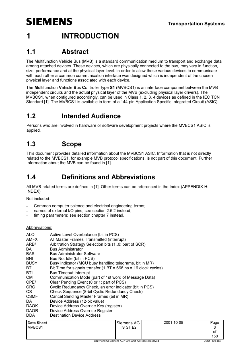
Abbreviations:
ALO
AMFX
ARBi
BA
BAS
BNI
BUSY
BT
BTI
CM
CPEi
CRC
CS
CSMF
DA
DAOK
DAOR
DDA
Active Level Overbalance (bit in PCS)
All Master Frames Transmitted (interrupt)
Arbitration Strategy Selection bits (1..0; part of SCR)
Bus Administrator
Bus Administrator Software
Bus Not Idle (bit in PCS)
Busy Indicator (MCU busy handling telegrams, bit in MR)
Bit Time for signals transfer (1 BT = 666 ns = 16 clock cycles)
Bus Timeout Interrupt
Communication Mode (part of 1st word of Message Data)
Clear Pending Event (0 or 1; part of PCS)
Cyclic Redundancy Check, an error indicator (bit in PCS)
Check Sequence (8-bit Cyclic Redundancy Check)
Cancel Sending Master Frames (bit in MR)
Device Address (12-bit value)
Device Address Override Key (register)
Device Address Override Register
Destination Device Address
Data Sheet
MVBCS1
Siemens AG
TS GT E2
2001-10-05
Page
6
of
150
Copyright (C) Siemens AG 1999-2001 All Rights Reserved
DSS1_100.doc
�
Transportation Systems
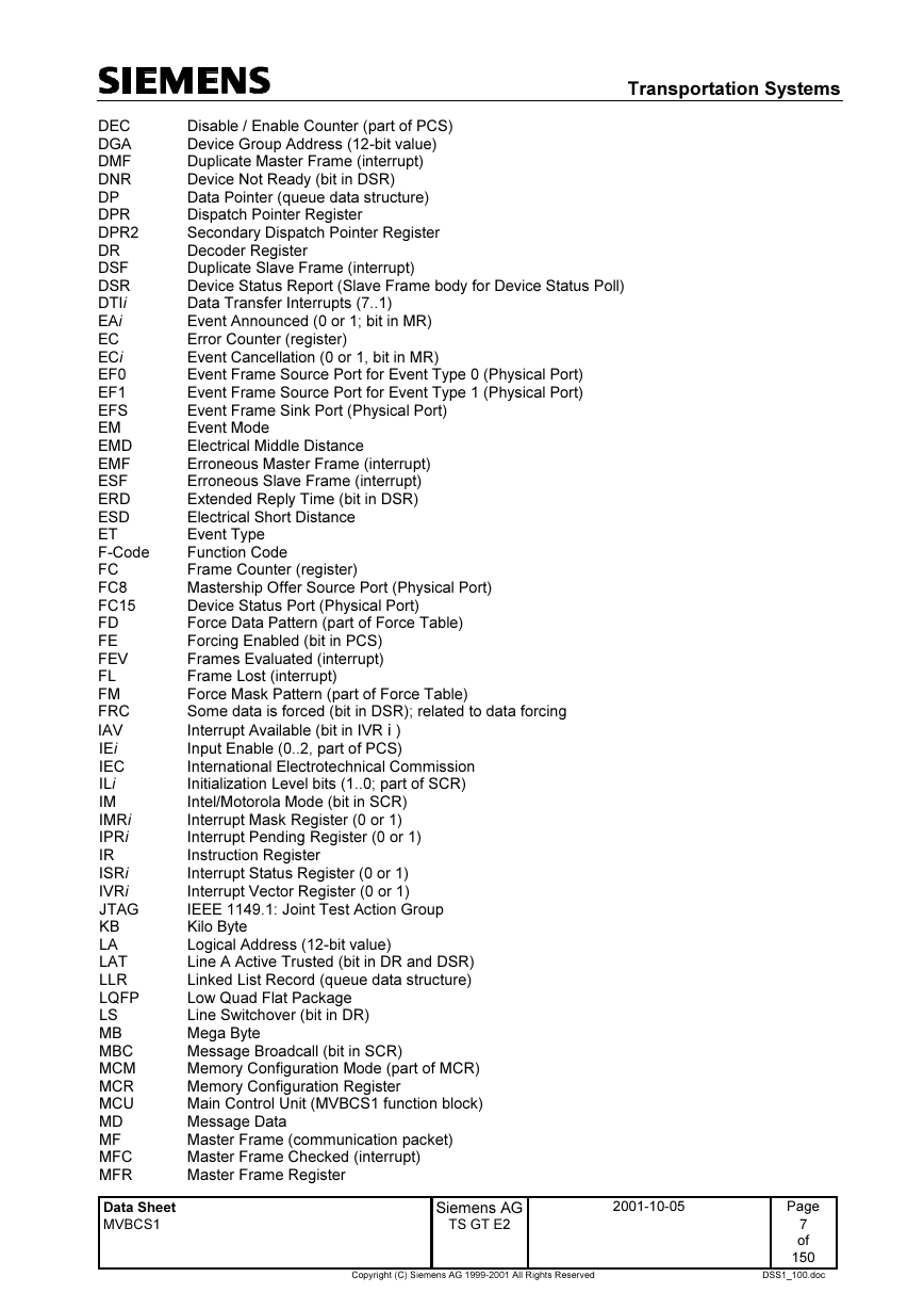
DEC
DGA
DMF
DNR
DP
DPR
DPR2
DR
DSF
DSR
DTIi
EAi
EC
ECi
EF0
EF1
EFS
EM
EMD
EMF
ESF
ERD
ESD
ET
F-Code
FC
FC8
FC15
FD
FE
FEV
FL
FM
FRC
IAV
IEi
IEC
ILi
IM
IMRi
IPRi
IR
ISRi
IVRi
JTAG
KB
LA
LAT
LLR
LQFP
LS
MB
MBC
MCM
MCR
MCU
MD
MF
MFC
MFR
Disable / Enable Counter (part of PCS)
Device Group Address (12-bit value)
Duplicate Master Frame (interrupt)
Device Not Ready (bit in DSR)
Data Pointer (queue data structure)
Dispatch Pointer Register
Secondary Dispatch Pointer Register
Decoder Register
Duplicate Slave Frame (interrupt)
Device Status Report (Slave Frame body for Device Status Poll)
Data Transfer Interrupts (7..1)
Event Announced (0 or 1; bit in MR)
Error Counter (register)
Event Cancellation (0 or 1, bit in MR)
Event Frame Source Port for Event Type 0 (Physical Port)
Event Frame Source Port for Event Type 1 (Physical Port)
Event Frame Sink Port (Physical Port)
Event Mode
Electrical Middle Distance
Erroneous Master Frame (interrupt)
Erroneous Slave Frame (interrupt)
Extended Reply Time (bit in DSR)
Electrical Short Distance
Event Type
Function Code
Frame Counter (register)
Mastership Offer Source Port (Physical Port)
Device Status Port (Physical Port)
Force Data Pattern (part of Force Table)
Forcing Enabled (bit in PCS)
Frames Evaluated (interrupt)
Frame Lost (interrupt)
Force Mask Pattern (part of Force Table)
Some data is forced (bit in DSR); related to data forcing
Interrupt Available (bit in IVR i )
Input Enable (0..2, part of PCS)
International Electrotechnical Commission
Initialization Level bits (1..0; part of SCR)
Intel/Motorola Mode (bit in SCR)
Interrupt Mask Register (0 or 1)
Interrupt Pending Register (0 or 1)
Instruction Register
Interrupt Status Register (0 or 1)
Interrupt Vector Register (0 or 1)
IEEE 1149.1: Joint Test Action Group
Kilo Byte
Logical Address (12-bit value)
Line A Active Trusted (bit in DR and DSR)
Linked List Record (queue data structure)
Low Quad Flat Package
Line Switchover (bit in DR)
Mega Byte
Message Broadcall (bit in SCR)
Memory Configuration Mode (part of MCR)
Memory Configuration Register
Main Control Unit (MVBCS1 function block)
Message Data
Master Frame (communication packet)
Master Frame Checked (interrupt)
Master Frame Register
Data Sheet
MVBCS1
Siemens AG
TS GT E2
2001-10-05
Page
7
of
150
Copyright (C) Siemens AG 1999-2001 All Rights Reserved
DSS1_100.doc
�
Transportation Systems
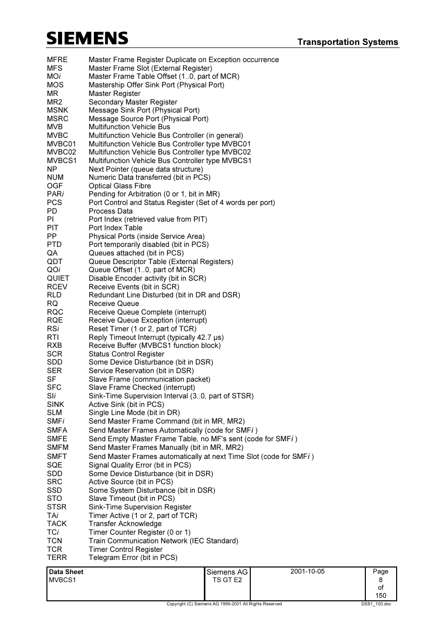
Master Frame Register Duplicate on Exception occurrence
MFRE
Master Frame Slot (External Register)
MFS
MOi
Master Frame Table Offset (1..0, part of MCR)
Mastership Offer Sink Port (Physical Port)
MOS
Master Register
MR
Secondary Master Register
MR2
Message Sink Port (Physical Port)
MSNK
Message Source Port (Physical Port)
MSRC
Multifunction Vehicle Bus
MVB
Multifunction Vehicle Bus Controller (in general)
MVBC
Multifunction Vehicle Bus Controller type MVBC01
MVBC01
MVBC02
Multifunction Vehicle Bus Controller type MVBC02
MVBCS1 Multifunction Vehicle Bus Controller type MVBCS1
NP
NUM
OGF
PARi
PCS
PD
PI
PIT
PP
PTD
QA
QDT
QOi
QUIET
RCEV
RLD
RQ
RQC
RQE
RSi
RTI
RXB
SCR
SDD
SER
SF
SFC
SIi
SINK
SLM
SMFi
SMFA
SMFE
SMFM
SMFT
SQE
SDD
SRC
SSD
STO
STSR
TAi
TACK
TCi
TCN
TCR
TERR
Next Pointer (queue data structure)
Numeric Data transferred (bit in PCS)
Optical Glass Fibre
Pending for Arbitration (0 or 1, bit in MR)
Port Control and Status Register (Set of 4 words per port)
Process Data
Port Index (retrieved value from PIT)
Port Index Table
Physical Ports (inside Service Area)
Port temporarily disabled (bit in PCS)
Queues attached (bit in PCS)
Queue Descriptor Table (External Registers)
Queue Offset (1..0, part of MCR)
Disable Encoder activity (bit in SCR)
Receive Events (bit in SCR)
Redundant Line Disturbed (bit in DR and DSR)
Receive Queue
Receive Queue Complete (interrupt)
Receive Queue Exception (interrupt)
Reset Timer (1 or 2, part of TCR)
Reply Timeout Interrupt (typically 42.7 µs)
Receive Buffer (MVBCS1 function block)
Status Control Register
Some Device Disturbance (bit in DSR)
Service Reservation (bit in DSR)
Slave Frame (communication packet)
Slave Frame Checked (interrupt)
Sink-Time Supervision Interval (3..0, part of STSR)
Active Sink (bit in PCS)
Single Line Mode (bit in DR)
Send Master Frame Command (bit in MR, MR2)
Send Master Frames Automatically (code for SMFi )
Send Empty Master Frame Table, no MF's sent (code for SMFi )
Send Master Frames Manually (bit in MR, MR2)
Send Master Frames automatically at next Time Slot (code for SMFi )
Signal Quality Error (bit in PCS)
Some Device Disturbance (bit in DSR)
Active Source (bit in PCS)
Some System Disturbance (bit in DSR)
Slave Timeout (bit in PCS)
Sink-Time Supervision Register
Timer Active (1 or 2, part of TCR)
Transfer Acknowledge
Timer Counter Register (0 or 1)
Train Communication Network (IEC Standard)
Timer Control Register
Telegram Error (bit in PCS)
Data Sheet
MVBCS1
Siemens AG
TS GT E2
2001-10-05
Page
8
of
150
Copyright (C) Siemens AG 1999-2001 All Rights Reserved
DSS1_100.doc
�



 2023年江西萍乡中考道德与法治真题及答案.doc
 2012年重庆南川中考生物真题及答案.doc
 2013年江西师范大学地理学综合及文艺理论基础考研真题.doc
 2020年四川甘孜小升初语文真题及答案I卷.doc
 2020年注册岩土工程师专业基础考试真题及答案.doc
 2023-2024学年福建省厦门市九年级上学期数学月考试题及答案.doc
 2021-2022学年辽宁省沈阳市大东区九年级上学期语文期末试题及答案.doc
 2022-2023学年北京东城区初三第一学期物理期末试卷及答案.doc
 2018上半年江西教师资格初中地理学科知识与教学能力真题及答案.doc
 2012年河北国家公务员申论考试真题及答案-省级.doc
 2020-2021学年江苏省扬州市江都区邵樊片九年级上学期数学第一次质量检测试题及答案.doc
 2022下半年黑龙江教师资格证中学综合素质真题及答案.doc