IEEE TRANSACTIONS ON HUMAN-MACHINE SYSTEMS, VOL. 46, NO. 5, OCTOBER 2016
761
iLeg—A Lower Limb Rehabilitation Robot: A Proof of Concept
Feng Zhang, Zeng-Guang Hou, Long Cheng, Weiqun Wang, Yixiong Chen, Jin Hu, Liang Peng, and Hongbo Wang
Abstract—In this paper, a robot, namely iLeg, is designed for the pur-
pose of rehabilitation of patients with hemiplegia or paraplegia. The iLeg
is composed of one reclining seat and two leg orthoses, and each leg ortho-
sis has three degrees of freedom, which correspond to the hip, knee, and
ankle. Based on this robotic system, two controllers, i.e., passive training
controller and active training controller, are proposed. The former takes ad-
vantage of the proportional-integral control method to solve the trajectory
tracking problem, and the latter employs the surface electromyography sig-
nals to achieve active training. Two simplified impedance controllers, i.e.,
damping-type velocity controller and spring-type position controller, are
designed for active training. A perceptron neural network detects move-
ment intentions. The performance of the controllers was investigated with
one able-bodied male. The results showed that the leg orthosis tracked the
predefined trajectory based on the passive training controller, with the er-
ror rates of 0.45%, 0.44%, and 0.27%, respectively, for the hip, knee,
and ankle. The active training controller whose loop rate is 6.67 Hz can
move the leg orthosis smoothly, and the average recognition error of the
perceptron neural network is less than 5%.
Index
electromyography
(EMG),
Terms—Active
training,
rehabilitation robot, spinal cord injury (SCI).
I. INTRODUCTION
S TROKE and spinal cord injury (SCI) often lead to long-
term limb dysfunctions, especially hemiplegia and para-
plegia. To improve neurorehabilitation and motor recovery, and
to avoid disuse atrophy of the lower limbs, repetitive and inten-
sive rehabilitation exercises with the disabled limbs are indis-
pensable. Traditional rehabilitation exercises that are conducted
manually with the help of therapists are not only labor intensive,
but also very costly. Rehabilitation bikes are often used in China
to help stroke or SCI patients do treadmill training, which has a
positive role on activities of daily living in convalescent stroke
patients [1]. The lower limb rehabilitation robot (LLRR) could
provide a more flexible alternative to rehabilitation bikes.
Manuscript received December 17, 2014; revised April 25, 2015, October
21, 2015, and January 10, 2016; accepted April 8, 2016. Date of publica-
tion July 7, 2016; date of current version September 14, 2016. This work
was supported in part by the National Natural Science Foundation of China
under Grant 61225017, Grant 61403378, Grant 61422310, Grant 61421004,
and Grant 61533016, and by the Strategic Priority Research Program of the
Chinese Academy of Sciences under Grant XDB02080000. This paper was rec-
ommended by Associate Editor J. L. Contreras-Vidal. (Corresponding author:
Zeng-Guang Hou.)
F. Zhang, Z.-G. Hou, L. Cheng, W. Wang, Y. Chen, J. Hu, and L. Peng are
with the State Key Laboratory of Management and Control for Complex Sys-
tems, Institute of Automation, Chinese Academy of Sciences, Beijing 100190,
China (e-mail: feng.zhang@ia.ac.cn; zengguang.hou@ia.ac.cn; long.cheng@
ia.ac.cn; weiqun.wang@ia.ac.cn; yixiong.chen@ia.ac.cn;
jin.hu@ia.ac.cn;
liang.peng@ia.ac.cn).
H. Wang is with the School of Mechanical Engineering, Yanshan University,
Qinhuangdao 066004, China (e-mail: hongbo_w@ysu.edu.cn).
Color versions of one or more of the figures in this paper are available online
at http://ieeexplore.ieee.org.
Digital Object Identifier 10.1109/THMS.2016.2562510
The LLRRs can be categorized into three types according to
their driving mechanisms and locomotor training styles. The first
one is the sitting/lying type that features a reclining seat and two
leg orthoses, e.g., MotionMaker [2]. It can be used for single-
and multiple-joint rehabilitation. The second one is the stand-
ing/walking type that usually comprises a step-posture control
system and a body weight support system, e.g., Lokomat [3],
LOPES [4], LokoHelp [5], ReoAmbulator [6], Gait Trainer [7],
HapticWalker [8], and WalkTrainer [9]. This type of LLRR as-
sists walking movements of gait-impaired patients and combines
intensive functional locomotion therapy with patient assessment
and feedback tools. The third one is the wearable exoskeleton
type that can be worn by the patient and assists him/her to stand
or walk, e.g., Ekso [10], Rex [11], Robot Suit HAL [12], and
ReWalk [13]. The effectiveness of LLRR is still an open topic
in the current literature. While some studies show their effec-
tiveness [3], [15], [16], other studies suggest that robotics are
not superior to traditional physical therapy [14].
The sitting/lying-type LLRR could provide a useful alterna-
tive to rehabilitation bikes, as it can help patients do not only
passive treadmill training, but also other types of training, such
as active training or functional electrical stimulation (FES). For
example, the MotionMakerTM takes advantage of FES to mimic
natural exercise during the rehabilitation [16].
Voluntary or active motor training has been proven more
beneficial than passive motor training in eliciting performance
improvements and cortical reorganization [17]; thus, an LLRR
that can help patients accomplish not only passive training, but
also active training would be more helpful. Electromyography
(EMG) that contains rich information of muscle activity and
voluntary intention can be used for this purpose. For example,
Leonard et al. developed a novel EMG-driven hand exoskeleton
for bilateral rehabilitation of grasping in stroke, and the EMG
signals from the nonparetic hand were used to estimate the
grasping force and then replicated as robotic assistance for the
paretic hand by means of the hand-exoskeleton [18]. Studies
also suggest that substantial motor control information can be
extracted from paretic muscles of stroke survivors by EMG
signals [19].
In this study, we introduce a novel sitting/lying-type LLRR,
namely iLeg. iLeg is intended for handicapped and hemiplegic
patients, and its main functions are training and rehabilitation
of articular mobility and movement coordination, as well as
muscular strength. The purpose of developing iLeg is to re-
place rehabilitation bikes and provide more rehabilitation train-
ing methods. Two rehabilitation training control methods, i.e.,
passive training and active training, are proposed. Two sim-
plified impedance control methods, i.e., spring-type position
control and damping-type velocity control based on EMG sig-
nals, are implemented to control the robot’s motion. Finally,
2168-2291 © 2016 IEEE. Personal use is permitted, but republication/redistribution requires IEEE permission.
See http://www.ieee.org/publications standards/publications/rights/index.html for more information.
�
762
IEEE TRANSACTIONS ON HUMAN-MACHINE SYSTEMS, VOL. 46, NO. 5, OCTOBER 2016
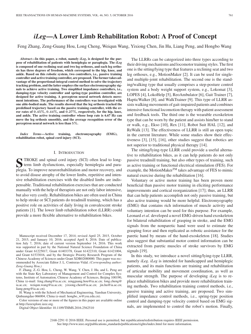
Fig. 1. Mechanism of iLeg. (a) Virtual prototype of iLeg. (b) Interior view of left leg orthosis mechanism. (c) Exterior view of left leg orthosis mechanism.
(d) Crus length adjusting mechanism.
TABLE I
ADJUSTMENT RANGES OF iLeg
JOINT ANGLE RANGES AND SPECIFICATIONS OF THE MOTORS OF iLeg
TABLE II
Item
Width
Thigh link
Crus link
Ankle link
◦
Item Minimal (
◦
) Maximal (
·
) Torque (N
m) Speed (r/min) Power (W) Reduction
Minimum (mm)
Maximum (mm)
400
540
315
395
325
420
90
90
Hip
Knee
Ankle
0
−120
−15
80
0
35
1.333
0.55
0.09
3200
4860
8600
447
280
79.4
120
180
190
the system performance is investigated in a proof-of-concept
evaluation.
II. SYSTEM DESIGN
A. Mechanical System Design
The virtual prototype of iLeg, which consists of one reclining
seat, two leg orthoses, two support mechanisms, one control box,
and a base, is shown in Fig. 1(a). The modular-design supports
assembling, debugging, and maintenance of iLeg. The seat back
◦
and 160
;
can be adjusted to an optional angle between 90
thus, the patient can sit or recline in the seat. Each leg orthosis is
mounted on an associated support mechanism, which can move
bidirectionally on the base; thus, the distance between two leg
orthoses can be adjusted. The distance is defined as the width
of iLeg (see Table I). It is adjusted to be consistent with the hip
width of the patient during training. The maximum adjustment
facilitates getting ON and OFF.
◦
B. Leg Orthosis
The two leg orthoses’ mechanical structures are symmetrical.
The virtual prototype of the left leg orthosis is shown in Fig. 1(b)
and (c). Each leg orthosis has three degrees of freedom, which
correspond to the hip, knee, and ankle. The leg orthosis can
simulate leg movements such as hip flexion/extension, knee
flexion/extension, ankle flexion/extension, and the coordinated
movements of the three joints. By considering the physiological
movement range of each joint of human leg [20], the movement
ranges of iLeg are given in Table II.
Each joint of the orthosis is driven by a DC servo motor,
and drive belts are used for energy transmission. By using the
drive belt, the motors can be located far away from the associ-
ated joints; thus, the mechanical structures of the thigh and crus
links can be smaller. Mechanical interference between the drive
units and robot links is eliminated. The ankle motor (32SYK60
of Saegmotory Co., Ltd., Shanghai, China) is located in the
pedal, and its output power is delivered to the ankle through a
driving belt which is hidden in the ankle link [see Fig. 1(b)]. This
addresses the limited space in the ankle. The hip and knee joints
are also driven this way. The drive unit of the knee is located
behind the hip joint. This novel design not only reduces the size
and complexity of the joint, but also offsets some weight of the
leg orthosis. The knee motor (48SYK91 of Saegmotory Co.,
Ltd., Shanghai, China) speed of the orthosis is reduced through
the harmonic transmission and multistage gear mechanism, in-
creasing output torque. The drive unit of the hip is placed on
the associated support mechanism to simplify the mechanical
structure of the orthosis, as shown in Fig. 1(a). The hip motor
(ID33004 of MCG, Inc., MN, USA) speed is reduced through a
harmonic speed reducer, and then, the power is delivered to the
hip through a driving belt. The specifications of the motors of
iLeg are given in Table II.
C. Adjusting Mechanism
The link length of the leg orthosis should be adjustable to
fit patients of different height (150–190 cm). iLeg can adjust
lengths of the thigh and crus by the associated electric length
�
IEEE TRANSACTIONS ON HUMAN-MACHINE SYSTEMS, VOL. 46, NO. 5, OCTOBER 2016
763
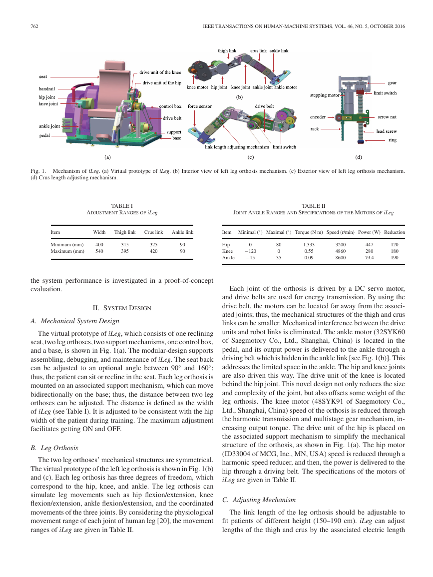
where x and y denote the coordinates of point P , lthigh and lcrus
are the lengths of thigh and crus links, and θhip and θknee are
the joint angles of hip and knee, respectively. According to (1),
we obtain the inverse kinematics of leg orthosis as
θhip = arctan
y
x
θknee = −arccos
l2
thigh
+ arccos
x2 + y2 − l2
thigh
2lthigh lcrus
− l2
crus + x2 + y2
2lthigh
− l2
x2 + y2
crus
.
(2)
Fig. 2. Kinematic model of the leg orthosis.
B. Passive Training Controller
By (2), we can obtain the joint trajectories once the trajectory
of point P is known.
adjusting mechanism; thus, the leg orthosis somewhat matches
the human leg. According to the respective proportion of thigh
and crus lengths to body height [21], the designed adjustment
ranges of each link are given in Table I. The length adjusting
mechanisms are implemented through telescopic mechanisms,
and each link can be controlled in a sliding groove to change
the length. The lead screw that is driven by a stepping motor
and associated screw nut is used to drive the mechanisms. The
prototype of the drive unit of the crus length adjusting mecha-
nism is shown in Fig. 1(d). The encoder in Fig. 1(d) is used to
measure the link length, and it moves together with the screw
nut along the rack. Limit switches are used to detect the limit
positions. One end of the crus length adjusting mechanism is
fixed to the knee joint, and the other end is connected to the crus
link through the screw nut. The thigh length adjusting mecha-
nism uses a similar idea, although it is implemented differently.
By using this driving method, the length adjusting mechanisms
move stably and smoothly. The ankle link shown in Fig. 1(b)
is the segment between the ankle joint and the pedal, and it
corresponds to the patient’s foot height. As there is no adjust-
ing mechanism, layers on the pedal can support patients with
different foot heights.
III. CONTROL METHODS
A. Kinematics
The leg orthosis has three serial links: thigh, crus, and ankle
[see Fig. 1(b)]. The kinematic model of the leg orthosis is shown
◦
when the thigh is parallel to
in Fig. 2. The hip joint angle is 0
the seat plane. Trajectory planning of the leg orthosis in the
Cartesian plane usually refers to the trajectory of point P which
is at the end of the crus link. The movement of the ankle joint is
often planned according to specific applications. For example,
for passive cycling training, the trajectory of point P is a circle
in the Cartesian plane, while the ankle joint can keep still during
the cycling movement. Thus, a simplified two-link model can
be used for the kinematic analysis of the leg orthosis.
We obtain the forward kinematics of leg orthosis as
x = lthigh cos(θhip) + lcrus cos(θhip + θknee)
y = lthigh sin(θhip) + lcrus sin(θhip + θknee)
(1)
The passive training controller solves the trajectory tracking
problem of the leg orthosis. A proportional-integral (PI) con-
troller is designed in the motor driver layer for this purpose. The
PI controller is composed of the current loop, velocity loop, and
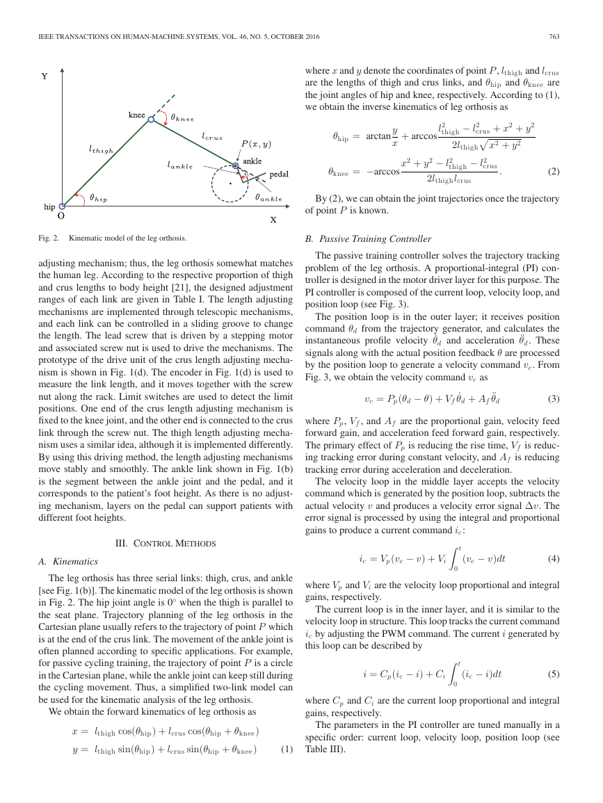
position loop (see Fig. 3).
The position loop is in the outer layer; it receives position
command θd from the trajectory generator, and calculates the
instantaneous profile velocity ˙θd and acceleration ¨θd. These
signals along with the actual position feedback θ are processed
by the position loop to generate a velocity command vc. From
Fig. 3, we obtain the velocity command vc as
˙θd + Af
vc = Pp(θd − θ) + Vf
¨θd
(3)
where Pp, Vf , and Af are the proportional gain, velocity feed
forward gain, and acceleration feed forward gain, respectively.
The primary effect of Pp is reducing the rise time, Vf is reduc-
ing tracking error during constant velocity, and Af is reducing
tracking error during acceleration and deceleration.
The velocity loop in the middle layer accepts the velocity
command which is generated by the position loop, subtracts the
actual velocity v and produces a velocity error signal Δv. The
error signal is processed by using the integral and proportional
gains to produce a current command ic:
ic = Vp(vc − v) + Vi
t
(vc − v)dt
(4)
0
where Vp and Vi are the velocity loop proportional and integral
gains, respectively.
The current loop is in the inner layer, and it is similar to the
velocity loop in structure. This loop tracks the current command
ic by adjusting the PWM command. The current i generated by
this loop can be described by
i = Cp(ic − i) + Ci
0
t
(ic − i)dt
(5)
where Cp and Ci are the current loop proportional and integral
gains, respectively.
The parameters in the PI controller are tuned manually in a
specific order: current loop, velocity loop, position loop (see
Table III).
�
764
IEEE TRANSACTIONS ON HUMAN-MACHINE SYSTEMS, VOL. 46, NO. 5, OCTOBER 2016
Fig. 3.
Structure of the PI controller.
TABLE III
PARAMETERS OF THE PI CONTROLLER
Joint
Hip
Knee
Ankle
P P
V f
A f
1800
1500
1300
6000
5200
4000
16384
15124
12571
V p
400
500
300
V i
10
20
15
C p
C i
68
100
200
138
120
158
C. Active Training Controller
1) Controller Design: For active training, the robot trajec-
tories are controlled by the patient. The robot, iLeg, detects
the patient’s motion intention and assists him/her to achieve it.
Impedance control is a popular method for active control of a
manipulator’s interactive behavior [22], [24]. The basic idea of
impedance control is to establish a mass–damper–spring rela-
tionship between the Cartesian position Δx and the Cartesian
torque/force τ as
τ = MΔ¨x + DΔ ˙x + KΔx
(6)
with the positive-definite matrices M, D, K representing the
virtual inertia, damping, and stiffness of the interactive system,
respectively. These matrices can be chosen by the control system
designer according to the goals to be achieved by the robot; thus,
impedance control does not attempt to track motion and force
trajectories but to regulate the mechanical impedance specified
by a target model [24].
Force/torque signals are important but not essential for
impedance control. Due to the virtuality of M, D, and K,
the Cartesian torque/force τ can also be replaced with other
signals. Surface electromyography (sEMG) is a physiological
signal, which represents the muscle strength directly; thus, it is
a suitable alternative for obtaining the Cartesian torque/force.
The human joint flexion and extension movements are con-
trolled by two muscle groups, i.e., agonist and antagonist, whose
roles are exchanged when the movement changes. Thus, sEMG
signals from the two muscle groups should be acquired simulta-
neously, and the role of each muscle group must be recognized
firstly. In this paper, the normalized amplitudes of sEMG are
directly used as the Cartesian forces. Finally, we obtain the
sEMG-based impedance controller for active training as
CA = MΔ¨θ + DΔ ˙θ + KΔθ
⎡
⎢
⎣
c1 −c2
0
0
0
0
C =
0
0
c3 −c4
0
0
0
0
0
0
c5 −c6
⎤
⎥
⎦
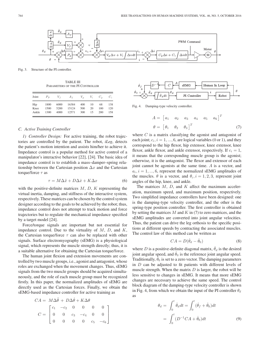
Fig. 4. Damping-type velocity controller.
a1
θ1
A =
θ =
a2
θ2
a3
θ3
T
T
a4
a5
a6
(7)
where C is a matrix classifying the agonist and antagonist of
each joint; ci, i = 1, ..., 6, are logical variables (0 or 1), and they
correspond to the hip flexor, hip extensor, knee extensor, knee
flexor, ankle flexor, and ankle extensor, respectively. If ci = 1,
it means that the corresponding muscle group is the agonist;
otherwise, it is the antagonist. The flexor and extensor of each
joint cannot be agonists at the same time. A is a vector, and
ai, i = 1, ..., 6, represent the normalized sEMG amplitudes of
the muscles. θ is a vector, and θi, i = 1, 2, 3, represent joint
angles of the hip, knee, and ankle.
The matrices M, D, and K affect the maximum acceler-
ation, maximum speed, and maximum position, respectively.
Two simplified impedance controllers have been designed: one
is the damping-type velocity controller, and the other is the
spring-type position controller. The first controller is obtained
by setting the matrices M and K in (7) to zero matrices, and the
sEMG amplitudes are converted into joint angular velocities.
Thus, the patient can drive the leg orthosis to the specific posi-
tions at different speeds by contracting the associated muscles.
The control law of this method can be written as
CA = D( ˙θd − ˙θ0)
(8)
where D is a positive-definite diagonal matrix, ˙θd is the desired
joint angular speed, and ˙θ0 is the reference joint angular speed.
Traditionally, ˙θ0 is set to a zero vector. The damping parameters
in D can be adjusted to fit patients with different levels of
muscle strength. When the matrix D is larger, the robot will be
less sensitive to changes in sEMG. It means that more sEMG
changes are necessary to achieve the same speed. The control
block diagram of the damping-type velocity controller is shown
in Fig. 4, from which we obtain the input of the PI controller θd
as
t
t
θd =
=
0
0
˙θd dt =
0
t
( ˙θf + ˙θ0)dt
−1CA + ˙θ0)dt
(D
(9)
�
IEEE TRANSACTIONS ON HUMAN-MACHINE SYSTEMS, VOL. 46, NO. 5, OCTOBER 2016
765
Fig. 5.
Spring-type position controller.
gi = g(yi) = g
⎝
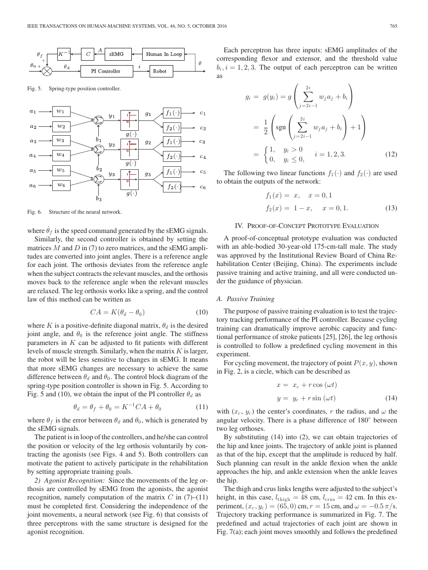
Each perceptron has three inputs: sEMG amplitudes of the
corresponding flexor and extensor, and the threshold value
bi, i = 1, 2, 3. The output of each perceptron can be written
as
⎛
2i
j=2i−1
⎞
wj aj + bi
⎠
⎛
⎝sgn
⎛
⎝
2i
j=2i−1
⎞
⎠ + 1
⎞
⎠
wj aj + bi
=
1
2
1,
0,
yi > 0
yi ≤ 0,
=
(12)
The following two linear functions f1(·) and f2(·) are used
to obtain the outputs of the network:
i = 1, 2, 3.
Fig. 6.
Structure of the neural network.
where ˙θf is the speed command generated by the sEMG signals.
Similarly, the second controller is obtained by setting the
matrices M and D in (7) to zero matrices, and the sEMG ampli-
tudes are converted into joint angles. There is a reference angle
for each joint. The orthosis deviates from the reference angle
when the subject contracts the relevant muscles, and the orthosis
moves back to the reference angle when the relevant muscles
are relaxed. The leg orthosis works like a spring, and the control
law of this method can be written as
CA = K(θd − θ0)
(10)
where K is a positive-definite diagonal matrix, θd is the desired
joint angle, and θ0 is the reference joint angle. The stiffness
parameters in K can be adjusted to fit patients with different
levels of muscle strength. Similarly, when the matrix K is larger,
the robot will be less sensitive to changes in sEMG. It means
that more sEMG changes are necessary to achieve the same
difference between θd and θ0. The control block diagram of the
spring-type position controller is shown in Fig. 5. According to
Fig. 5 and (10), we obtain the input of the PI controller θd as
θd = θf + θ0 = K
−1CA + θ0
(11)
where θf is the error between θd and θ0, which is generated by
the sEMG signals.
The patient is in loop of the controllers, and he/she can control
the position or velocity of the leg orthosis voluntarily by con-
tracting the agonists (see Figs. 4 and 5). Both controllers can
motivate the patient to actively participate in the rehabilitation
by setting appropriate training goals.
2) Agonist Recognition: Since the movements of the leg or-
thosis are controlled by sEMG from the agonists, the agonist
recognition, namely computation of the matrix C in (7)–(11)
must be completed first. Considering the independence of the
joint movements, a neural network (see Fig. 6) that consists of
three perceptrons with the same structure is designed for the
agonist recognition.
f1(x) = x,
f2(x) = 1 − x,
x = 0, 1
x = 0, 1.
(13)
IV. PROOF-OF-CONCEPT PROTOTYPE EVALUATION
A proof-of-conceptual prototype evaluation was conducted
with an able-bodied 30-year-old 175-cm-tall male. The study
was approved by the Institutional Review Board of China Re-
habilitation Center (Beijing, China). The experiments include
passive training and active training, and all were conducted un-
der the guidance of physician.
A. Passive Training
The purpose of passive training evaluation is to test the trajec-
tory tracking performance of the PI controller. Because cycling
training can dramatically improve aerobic capacity and func-
tional performance of stroke patients [25], [26], the leg orthosis
is controlled to follow a predefined cycling movement in this
experiment.
For cycling movement, the trajectory of point P (x, y), shown
in Fig. 2, is a circle, which can be described as
x = xc + r cos (ωt)
y = yc + r sin (ωt)
(14)
with (xc, yc) the center’s coordinates, r the radius, and ω the
◦
between
angular velocity. There is a phase difference of 180
two leg orthoses.
By substituting (14) into (2), we can obtain trajectories of
the hip and knee joints. The trajectory of ankle joint is planned
as that of the hip, except that the amplitude is reduced by half.
Such planning can result in the ankle flexion when the ankle
approaches the hip, and ankle extension when the ankle leaves
the hip.
The thigh and crus links lengths were adjusted to the subject’s
height, in this case, lthigh = 48 cm, lcrus = 42 cm. In this ex-
periment, (xc , yc) = (65, 0) cm, r = 15 cm, and ω = −0.5 π/s.
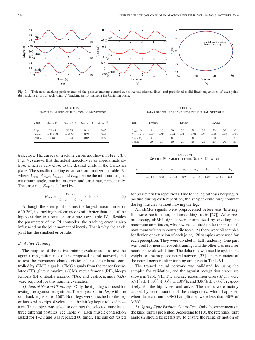
Trajectory tracking performance is summarized in Fig. 7. The
predefined and actual trajectories of each joint are shown in
Fig. 7(a); each joint moves smoothly and follows the predefined
�
766
IEEE TRANSACTIONS ON HUMAN-MACHINE SYSTEMS, VOL. 46, NO. 5, OCTOBER 2016
Fig. 7. Trajectory tracking performance of the passive training controller. (a) Actual (dashed lines) and predefined (solid lines) trajectories of each joint.
(b) Tracking errors of each joint. (c) Tracking performance in the Cartesian plane.
TRACKING ERRORS OF THE CYCLING MOVEMENT
DATA USED TO TRAIN AND TEST THE NEURAL NETWORK
TABLE IV
TABLE V
Joint
Hip
Knee
Ankle
◦
A m i n (
)
◦
A m a x (
)
◦
E m a x (
)
E rate (%)
21.68
−112.89
0.84
58.29
−54.66
19.14
0.16
0.26
0.05
0.45
0.44
0.27
Item
TF/GM
RF/BF
TA/GA
◦
)
θh i p (
◦
θk n e e (
◦
θankle (
Times
)
)
0
−90
0
20
30
−90
0
20
60
−90
0
20
30
−30
0
20
30
−60
0
20
30
−90
0
20
30
−90
−10
20
30
−90
0
20
30
−90
20
20
trajectory. The curves of tracking errors are shown in Fig. 7(b).
Fig. 7(c) shows that the actual trajectory is an approximate el-
lipse which is very close to the desired circle in the Cartesian
plane. The specific tracking errors are summarized in Table IV,
where Amin, Amax, Emax, and Erate denote the minimum angle,
maximum angle, maximum error, and error rate, respectively.
The error rate Erate is defined by
Erate =
Emax
Amax − Amin
× 100%.
(15)
Although the knee joint obtains the largest maximum error
of 0.26◦
, its tracking performance is still better than that of the
hip joint due to a smaller error rate (see Table IV). Besides
the parameters of the PI controller, the tracking error is also
influenced by the joint moment of inertia. That is why, the ankle
joint has the smallest error rate.
B. Active Training
The purpose of the active training evaluation is to test the
agonist recognition rate of the proposed neural network, and
to test the movement characteristics of the leg orthoses con-
trolled by sEMG signals. sEMG signals from the tensor fasciae
latae (TF), gluteus maximus (GM), rectus femoris (RF), biceps
femoris (BF), tibialis anterior (TA), and gastrocnemius (GA)
were acquired for this training evaluation.
1) Neural Network Training: Only the right leg was used for
testing the agonist recognition. The subject sat in iLeg with the
seat back adjusted to 150◦
. Both legs were attached to the leg
orthoses with strips of velcro, and the left leg kept a relaxed pos-
ture. The subject was asked to contract the selected muscles at
three different postures (see Table V). Each muscle contraction
lasted for 1–2 s and was repeated 60 times. The subject rested
SPECIFIC PARAMETERS OF THE NEURAL NETWORK
TABLE VI
w 1
0.15
w 2
−0.11
w 3
0.31
w 4
−0.20
w 5
0.25
w 6
−0.30
b1
0.06
b2
−0.05
b3
0.03
for 30 s every ten repetitions. Due to the leg orthosis keeping its
posture during each repetition, the subject could only contract
the leg muscles without moving the leg.
All sEMG signals were preprocessed before use (filtering,
full-wave rectification, and smoothing, as in [27]). After pre-
processing, sEMG signals were normalized by dividing the
maximum amplitudes, which were acquired under the muscles’
maximum voluntary contractile force. As there were 60 samples
for flexion or extension of each joint, 120 samples were used for
each perceptron. They were divided in half randomly. One part
was used for neural network training, and the other was used for
neural network validation. The delta rule was used to update the
weights of the proposed neural network [23]. The parameters of
the neural network after training are given in Table VI.
The trained neural network was validated by using the
samples for validation, and the agonist recognition errors are
shown in Table VII. The average recognition errors Emean were
5.71% ± 1.30%, 4.05% ± 1.07%, and 3.06% ± 1.05%, respec-
tively, for the hip, knee, and ankle. The errors were mainly
caused by cocontraction of the antagonists, which happened
when the maximum sEMG amplitudes were less than 30% of
MVC.
2) Spring-Type Position Controller: Only the experiment on
the knee joint is presented. According to (10), the reference joint
angle θ0 should be set firstly. To ensure the range of motion of
�
IEEE TRANSACTIONS ON HUMAN-MACHINE SYSTEMS, VOL. 46, NO. 5, OCTOBER 2016
767
TABLE VII
AGONIST RECOGNITION ERROR
Joint
Posture 1 (%)
Posture 2 (%)
Posture 3 (%)
Hip
Knee
Ankle
7.15
5.26
3.52
5.36
3.65
3.80
4.62
3.23
1.85
E mean (%)
5.71 ± 1.30
4.05 ± 1.07
3.06 ± 1.05
Fig. 9. Results of the damping-type velocity controller. (a) sEMG amplitudes
of RF. (b) sEMG amplitudes of BF. (c) Knee joint angles of the leg orthosis.
to the matrix K and sEMG changes. The response time is always
less than 1/fc. If the current movement is not finished in 1/fc,
the controller will stop it and start the next loop.
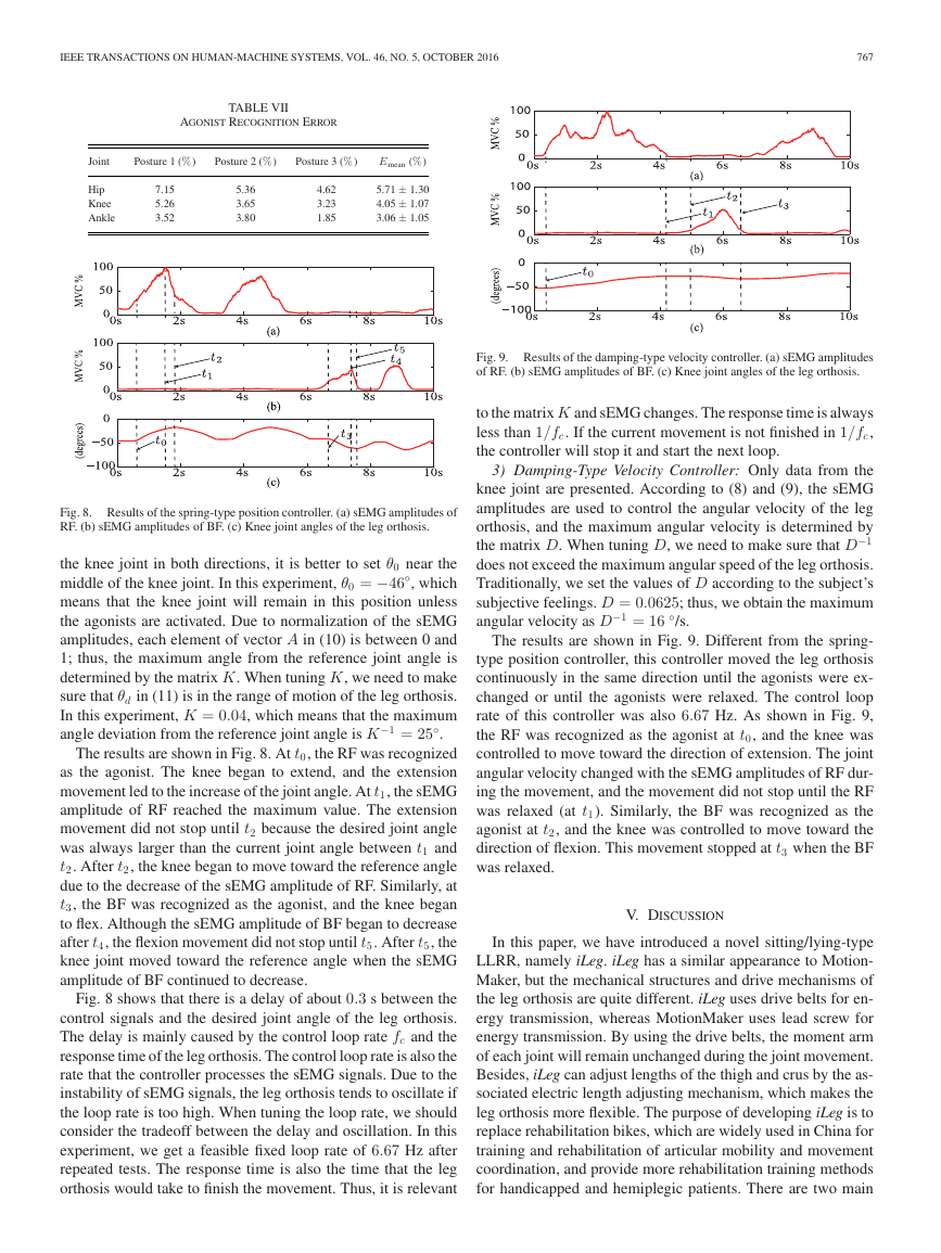
Fig. 8. Results of the spring-type position controller. (a) sEMG amplitudes of
RF. (b) sEMG amplitudes of BF. (c) Knee joint angles of the leg orthosis.
the knee joint in both directions, it is better to set θ0 near the
middle of the knee joint. In this experiment, θ0 = −46◦
, which
means that the knee joint will remain in this position unless
the agonists are activated. Due to normalization of the sEMG
amplitudes, each element of vector A in (10) is between 0 and
1; thus, the maximum angle from the reference joint angle is
determined by the matrix K. When tuning K, we need to make
sure that θd in (11) is in the range of motion of the leg orthosis.
In this experiment, K = 0.04, which means that the maximum
angle deviation from the reference joint angle is K
−1 = 25◦
.
The results are shown in Fig. 8. At t0, the RF was recognized
as the agonist. The knee began to extend, and the extension
movement led to the increase of the joint angle. At t1, the sEMG
amplitude of RF reached the maximum value. The extension
movement did not stop until t2 because the desired joint angle
was always larger than the current joint angle between t1 and
t2. After t2, the knee began to move toward the reference angle
due to the decrease of the sEMG amplitude of RF. Similarly, at
t3, the BF was recognized as the agonist, and the knee began
to flex. Although the sEMG amplitude of BF began to decrease
after t4, the flexion movement did not stop until t5. After t5, the
knee joint moved toward the reference angle when the sEMG
amplitude of BF continued to decrease.
Fig. 8 shows that there is a delay of about 0.3 s between the
control signals and the desired joint angle of the leg orthosis.
The delay is mainly caused by the control loop rate fc and the
response time of the leg orthosis. The control loop rate is also the
rate that the controller processes the sEMG signals. Due to the
instability of sEMG signals, the leg orthosis tends to oscillate if
the loop rate is too high. When tuning the loop rate, we should
consider the tradeoff between the delay and oscillation. In this
experiment, we get a feasible fixed loop rate of 6.67 Hz after
repeated tests. The response time is also the time that the leg
orthosis would take to finish the movement. Thus, it is relevant
3) Damping-Type Velocity Controller: Only data from the
knee joint are presented. According to (8) and (9), the sEMG
amplitudes are used to control the angular velocity of the leg
orthosis, and the maximum angular velocity is determined by
−1
the matrix D. When tuning D, we need to make sure that D
does not exceed the maximum angular speed of the leg orthosis.
Traditionally, we set the values of D according to the subject’s
subjective feelings. D = 0.0625; thus, we obtain the maximum
angular velocity as D
−1 = 16 ◦
/s.
The results are shown in Fig. 9. Different from the spring-
type position controller, this controller moved the leg orthosis
continuously in the same direction until the agonists were ex-
changed or until the agonists were relaxed. The control loop
rate of this controller was also 6.67 Hz. As shown in Fig. 9,
the RF was recognized as the agonist at t0, and the knee was
controlled to move toward the direction of extension. The joint
angular velocity changed with the sEMG amplitudes of RF dur-
ing the movement, and the movement did not stop until the RF
was relaxed (at t1). Similarly, the BF was recognized as the
agonist at t2, and the knee was controlled to move toward the
direction of flexion. This movement stopped at t3 when the BF
was relaxed.
V. DISCUSSION
In this paper, we have introduced a novel sitting/lying-type
LLRR, namely iLeg. iLeg has a similar appearance to Motion-
Maker, but the mechanical structures and drive mechanisms of
the leg orthosis are quite different. iLeg uses drive belts for en-
ergy transmission, whereas MotionMaker uses lead screw for
energy transmission. By using the drive belts, the moment arm
of each joint will remain unchanged during the joint movement.
Besides, iLeg can adjust lengths of the thigh and crus by the as-
sociated electric length adjusting mechanism, which makes the
leg orthosis more flexible. The purpose of developing iLeg is to
replace rehabilitation bikes, which are widely used in China for
training and rehabilitation of articular mobility and movement
coordination, and provide more rehabilitation training methods
for handicapped and hemiplegic patients. There are two main
�
768
IEEE TRANSACTIONS ON HUMAN-MACHINE SYSTEMS, VOL. 46, NO. 5, OCTOBER 2016
differences between iLeg and the current popular LLRRs. One
is the novel mechanism design, and the other is the passive and
active training control methods. Thus, iLeg has not only all the
functions of a rehabilitation bike, but also can provide sEMG-
based active rehabilitation training methods. Because China has
the largest population in the world, iLeg is expected to be widely
used in China.
Compared with the standing/walking-type LLRRs, such as
the Lokomat or LOPES, the training trajectories of iLeg are
more diverse, such as cycling movement. This novel system
may help patients perform uniarticular training, which provides
convenience for targeted joint rehabilitation, such as foot drop.
The sEMG-based impedance controllers detect not only the
subject’s movement intention, but also voluntary participation,
which may encourage a patient to move his/her legs. Compared
to existing techniques, the active training controllers proposed
in this paper do not need the user to remember the relationship
between the muscle contraction and the motion. Moreover, since
the position or velocity of the leg orthosis is determined by the
sEMG amplitudes, the user may try his/her best to contract
the muscles to generate strong sEMG amplitudes during each
rehabilitation session. Such voluntary participation could make
the rehabilitation training more effective.
Muscle spasm should be considered seriously during active
rehabilitation. The sEMG should be treated as abnormal signal
when muscle spasm happens, and the controllers should stop
iLeg immediately to avoid secondary damage to the subject.
Although studies have suggested that substantial motor control
information can be extracted from paretic muscles of stroke
survivors by EMG signals [19], there are still many challenges
when impaired subjects try and use iLeg. People with stroke
and SCI typically are weak and have relatively small EMG
amplitudes and abnormal muscle coordination patterns that may
make it difficult for them to control iLeg. To deal with these
challenges, we should focus on two aspects. One is choosing the
appropriate EMG signals that can describe the motion intention
of patients, and the other is improving the motion intention
recognition algorithm. In our future work, we will focus on the
clinical validation of this system.
ACKNOWLEDGMENT
The authors are grateful to Dr. Y. Hong, J. Zhang, and Z. Lu with the
China Rehabilitation Research Center, Beijing, China, for providing
suggestions.
REFERENCES
[1] G. Yan, H. Shen, X. Zhao, Q. Wei, Y. Kang, Z. Jia, L. Song, and M. Huang,
“Effects of treadmill training on ADL of convalescent stroke patients,”
Chin. J. Rehabil., vol. 22, no. 3, pp. 163–164, 2007.
[2] C. Schmitt, P. M´etrailler, A. Al-Khodairy, R. Brodard, J. Fournier,
M. Bouri, and R. Clavel, “The Motion MakerTM: A rehabilitation system
combining an orthosis with closed-loop electrical muscle stimulation,” in
Proc. 8th Vienna Int. Workshop Funct. Elect. Stimul., Vienna, Austria,
2004, pp. 117–120.
[3] M. A. Maestro, A. E. Ruz, R. M. Casado-Lopez, A. M. Gonzalez,
G. P. Mateos, E. G. Valdizan, and J. L. Martin, “Lokomat robotic-assisted
versus overground training within 3 to 6 months of incomplete spinal
cord lesion: Randomized controlled trial,” Neuralrehabil. Neural Repair,
vol. 26, no. 9, pp. 1058–1063, 2012.
[4] J. F. Veneman, R. Kruidhof, E. E. G. Hekman, R. Ekkelenkamp, E. H.
F. van Asseldonk, and H. van der Kooij, “Design and evaluation of the
LOPES exoskeleton robot for interactive gait rehabilitation,” IEEE Trans.
Neural Syst. Rehabil. Eng., vol. 15, no. 3, pp. 379–386, Sep. 2007.
[5] S. Freivogel, J. Mehrholz, T. Husak-Sotomayor, and D. Schmalohr, “Gait
training with the newly developed ‘LokoHelp’-system is feasible for non-
ambulatory patients after stroke, spinal cord and brain injury: A feasibility
study, Brain Injury, vol. 22, nos. 7/8, pp. 625–632, 2008.
[6] G. R. West, “Powered gait orthosis and method of utilizing same,” Patent
6 689 075, 2004.
[7] S. Hesse, C. Werner, D. Uhlenbrock, S. Frankenberg, A. Bardeleben, and
B. Brandl-Hesse, “An electromechanical gait trainer for restoration of gait
in hemiparetic stroke patients: Preliminary results,” Neurorehabil. Neural
Repair, vol. 15, no. 1, pp. 39–50, 2001.
[8] H. Schmidt, “HapticWalker—A novel haptic device for walking simula-
tion,” in Proc. EuroHaptics, Munich Germany, 2004, pp. 66–70.
[9] Y. Stauffer, Y. Allemand, M. Bouri, J. Fournier, R. Clavel, P. Metrailler,
R. Brodard, and F. Reynard, “The WalkTrainer—A new generation of
walking reeducation device combining orthoses and muscle stimulation,”
IEEE Trans. Neural Syst. Rehabil. Eng., vol. 17, no. 1, pp. 38–45, Feb.
2009.
[10] E. Strickland, “Good-bye, wheelchair,” IEEE Spectr., vol. 49, no. 1,
pp. 30–32, Jan. 2012.
[11] Rex Bionics REX web site, 2014. [Online]. Available: http://www.
rexbionics.com
[12] A. Tsukahara, R. Kawanishi, Y. Hasegawa, and Y. Sankai, “Sit-to-stand
and stand-to-sit transfer support for complete paraplegic patients with
robot suit HAL,” Adv. Robot., vol. 24, no. 11, pp. 1615–1638, 2010.
[13] Argo Medical Technologies ReWalk web site, 2014. [Online]. Available:
http://www.argomedtec.com
[14] B. H. Dobkin and P. W. Duncan, “Should body weight-supported treadmill
training and robotic-assistive steppers for locomotor training trot back to
the starting gate?” Neurorehabil. Neural Repair, vol. 26, no. 4, pp. 308–
317, 2012.
[15] S. Freivoqel, D. Schmalohr, and J. Mehrholz, “Improved walking ability
and reduced therapeutic stress with an electromechanical gait device,” J.
Rehabil. Med., vol. 41, no. 9, pp. 734–739, 2009.
[16] P. Metrailler
et al., “Improvement of rehabilitation possibilities with
the MotionMakerTM,” in Proc. 1st IEEE/RAS-EMBS Int. Conf. Biomed.
Robot. Biomechatron., 2006, pp. 359–364.
[17] M. Lotze, C. Braun, N. Birbaumer, S. Anders, and L. G. Cohen, “Mo-
tor learning elicited by voluntary drive,” Brain, vol. 126, pp. 866–872,
2003.
[18] D. Leonardis et al., “An EMG-controlled robotic hand exoskeleton for
bilateral rehabilitation,” IEEE Trans. Haptics, vol. 8, no. 2, pp. 140–151,
Apr.–Jun. 2015.
[19] X. Zhang and P. Zhou, “High-density myoelectric pattern recogni-
tion toward improved stroke rehabilitation,” IEEE Trans. Biomed. Eng.,
vol. 59, no. 6, pp. 1649–1657, Jun. 2012.
[20] A. Roaas and G. B. J. Andersson, “Normal range of motion of the hip, knee
and ankle joints in male subjects, 30–40 years of age,” Acta Orthopaedica
Scandinavica, vol. 53, pp. 205–208, 1982
[21] Y-C. Lin, M-J. J. Wang, and E. M. Wang, “The comparisons of anthropo-
metric characteristics among four peoples in East Asia,” Appl. Ergonom.,
vol. 35, no. 2, pp. 173–178, 2004.
[22] N. Hogan, “Impedance control: An approach to manipulation: Parts I-III,”
J. Dyn. Syst. Meas. Control, vol. 107, no. 1, pp. 1–24, 1985.
[23] B. Widrow and M. E. Hoff, “Adaptive switching circuits,” in Proc. IRE
WESCON Convention Rec., 1960, pp. 96–104.
[24] C. C. Cheah and D. Wang, “Learning impedance control for robotic ma-
nipulators,” IEEE Trans. Robot. Autom., vol. 14, no. 3, pp. 452–465, Jun.
1998.
[25] K. L. Michal, “The influence of early cycling training on balance in
stroke patients at the subacute stage: Results of a preliminary trial,” Clin.
Rehabil., vol. 20, no. 5, pp. 398–405, 2006.
[26] W. J. Thomas, J. M. Beltman, P. Elich, P. A. Koppe, H. Konijnenbelt,
A. de Haan, and K. H. Gerrits, “Effects of electric stimulation-assisted
cycling training in people with chronic stroke,” Arch. Phys. Med. Rehabil.,
vol. 89, no. 3, pp. 463–469, 2008.
[27] F. Zhang, P. Li, Z.-G. Hou, Z. Lu, Y. Chen, Q. Li, and M. Tan, “sEMG-
based continuous estimation of joint angles of human legs by using
BP neural network,” Neurocomputing, vol. 78, no. 1, pp. 139–148,
2012.
�


 2023年江西萍乡中考道德与法治真题及答案.doc
 2012年重庆南川中考生物真题及答案.doc
 2013年江西师范大学地理学综合及文艺理论基础考研真题.doc
 2020年四川甘孜小升初语文真题及答案I卷.doc
 2020年注册岩土工程师专业基础考试真题及答案.doc
 2023-2024学年福建省厦门市九年级上学期数学月考试题及答案.doc
 2021-2022学年辽宁省沈阳市大东区九年级上学期语文期末试题及答案.doc
 2022-2023学年北京东城区初三第一学期物理期末试卷及答案.doc
 2018上半年江西教师资格初中地理学科知识与教学能力真题及答案.doc
 2012年河北国家公务员申论考试真题及答案-省级.doc
 2020-2021学年江苏省扬州市江都区邵樊片九年级上学期数学第一次质量检测试题及答案.doc
 2022下半年黑龙江教师资格证中学综合素质真题及答案.doc