VC709 Evaluation
Board for the
Virtex-7 FPGA
User Guide
UG887 (v1.4) December 4, 2014
�
The information disclosed to you hereunder (the “Materials”) is provided solely for the selection and use of Xilinx products. To the maximum
extent permitted by applicable law: (1) Materials are made available "AS IS" and with all faults, Xilinx hereby DISCLAIMS ALL
WARRANTIES AND CONDITIONS, EXPRESS, IMPLIED, OR STATUTORY, INCLUDING BUT NOT LIMITED TO WARRANTIES OF
MERCHANTABILITY, NON-INFRINGEMENT, OR FITNESS FOR ANY PARTICULAR PURPOSE; and (2) Xilinx shall not be liable (whether
in contract or tort, including negligence, or under any other theory of liability) for any loss or damage of any kind or nature related to, arising
under, or in connection with, the Materials (including your use of the Materials), including for any direct, indirect, special, incidental, or
consequential loss or damage (including loss of data, profits, goodwill, or any type of loss or damage suffered as a result of any action
brought by a third party) even if such damage or loss was reasonably foreseeable or Xilinx had been advised of the possibility of the same.
Xilinx assumes no obligation to correct any errors contained in the Materials or to notify you of updates to the Materials or to product
specifications. You may not reproduce, modify, distribute, or publicly display the Materials without prior written consent. Certain products are
subject to the terms and conditions of Xilinx’s limited warranty, please refer to Xilinx’s Terms of Sale which can be viewed at
http://www.xilinx.com/legal.htm#tos; IP cores may be subject to warranty and support terms contained in a license issued to you by Xilinx.
Xilinx products are not designed or intended to be fail-safe or for use in any application requiring fail-safe performance; you assume sole risk
and liability for use of Xilinx products in such critical applications, please refer to Xilinx’s Terms of Sale which can be viewed at
http://www.xilinx.com/legal.htm#tos.
© Copyright 2013–2014 Xilinx, Inc. Xilinx, the Xilinx logo, Artix, ISE, Kintex, Spartan, Vivado, Virtex, Zynq, and other designated brands
included herein are trademarks of Xilinx in the United States and other countries. PCI, PCI Express, PCIe, and PCI-X are trademarks of
PCI-SIG. All other trademarks are the property of their respective owners.
Revision History
The following table shows the revision history for this document.
,
Date
Version
02/04/2013
06/04/2013
1.0
1.1
01/07/2014
1.2
03/11/2014
04/30/2014
1.2.1
1.3
Revision
Initial Xilinx release.
Changed XC7VX690T-2FFG1761CES to XC7VX690T-2FFG1761C throughout the
document. Changed SiT9122 to SiT9102. The data rate in Linear BPI Flash Memory,
page 22 changed from 40 MHz to 80 MHz. Added items 28 and 29 to the board
photograph in Figure 1-2. FPGA EMCC clock information was added to Table 1-7,
Table 1-8, Figure 1-13, and FPGA EMCC Clock, page 34. In Table 1-18, the DS1
description for RED changed. Replaced Figure 1-22 Configuration Mode and Upper Linear
Flash Address Switch. Enhanced section Switches, page 52. Updated part ordering
information in FMC_VADJ Voltage, page 62. Updated Figure 1-29 VC709 Board
Configuration Circuit. Replaced Appendix C, Master UCF Listing with Master Constraints
File Listing. Updated References, page 97.
Revised the content of Table 1-16, page 46. Revised Table 1-20 to correct connection of
FMC1_HPC_LA29_N, page 58 to FPGA pin T30 (Was W30). Revised all links and
references in Appendix F, Additional Resources and revised links to web pages and
documents throughout document to conform to latest linking style convention. Added
caution note about power connections to J18 on the VC709 board on page 98. Revised
link under Declaration of Conformity in Appendix G to point directly at the Certificate
PDF instead of XTP251, the list of Certificates of Conformity.
Tech Pubs edit. Technical content not affected.
Revised the data rate for the small outline dual-inline memory modules (SODIMMs)
in VC709 Board Features and Dual DDR3 Memory SODIMMs.
VC709 Evaluation Board
www.xilinx.com
UG887 (v1.4) December 4, 2014
�
Date
Version
12/04/2014
1.4
Revision
Added MT28GU01GAAA1EGC-0SIT part number for the BPI parallel NOR flash
memory component to Table 1-1, Linear BPI Flash Memory, and References. Added a
note to Table 1-1. Updated User SMA Clock (USER_SMA_CLOCK_P and
USER_SMA_CLOCK_N), Jitter-Attenuated Clock, I2C Bus, and Power Management.
Updated part number in Figure 1-4. Updated Figure 1-11 to correct net names. Added
I/O standard information to Table 1-4, Table 1-5, Table 1-6, Table 1-8, Table 1-14,
Table 1-19, and Table 1-20. Added PCIe® edge connector information after Table 1-12.
Updated description for XADC_GPIO_3, 2, 1, 0 in Table 1-25. Updated Table A-3 and
added Figure A-3. Updated VC709 Board XDC Listing. Updated References.
UG887 (v1.4) December 4, 2014
www.xilinx.com
VC709 Evaluation Board
�
VC709 Evaluation Board
www.xilinx.com
UG887 (v1.4) December 4, 2014
�
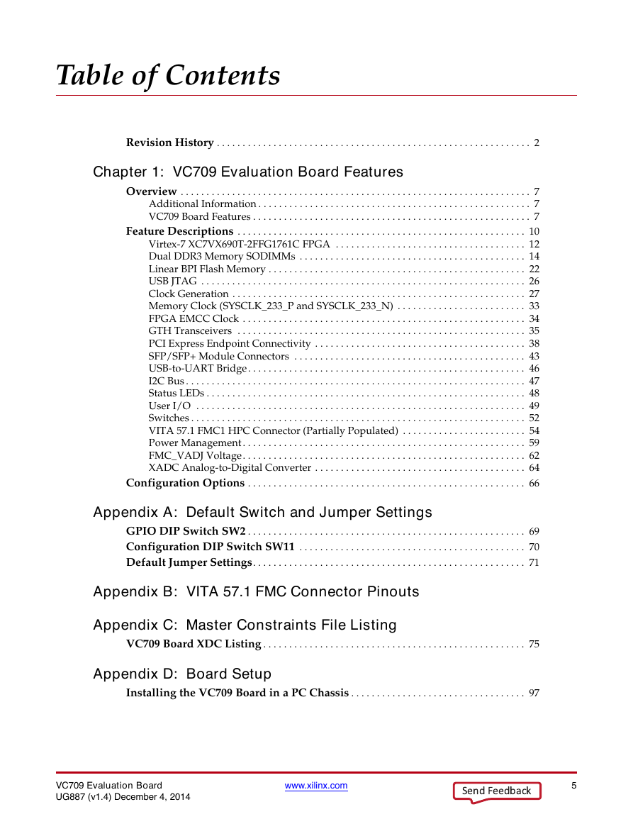
Table of Contents
Revision History . . . . . . . . . . . . . . . . . . . . . . . . . . . . . . . . . . . . . . . . . . . . . . . . . . . . . . . . . . . . . 2
Chapter 1: VC709 Evaluation Board Features
Overview . . . . . . . . . . . . . . . . . . . . . . . . . . . . . . . . . . . . . . . . . . . . . . . . . . . . . . . . . . . . . . . . . . . . 7
Additional Information . . . . . . . . . . . . . . . . . . . . . . . . . . . . . . . . . . . . . . . . . . . . . . . . . . . . . 7
VC709 Board Features . . . . . . . . . . . . . . . . . . . . . . . . . . . . . . . . . . . . . . . . . . . . . . . . . . . . . . 7
Feature Descriptions . . . . . . . . . . . . . . . . . . . . . . . . . . . . . . . . . . . . . . . . . . . . . . . . . . . . . . . . 10
Virtex-7 XC7VX690T-2FFG1761C FPGA . . . . . . . . . . . . . . . . . . . . . . . . . . . . . . . . . . . . . 12
Dual DDR3 Memory SODIMMs . . . . . . . . . . . . . . . . . . . . . . . . . . . . . . . . . . . . . . . . . . . . 14
Linear BPI Flash Memory . . . . . . . . . . . . . . . . . . . . . . . . . . . . . . . . . . . . . . . . . . . . . . . . . . 22
USB JTAG . . . . . . . . . . . . . . . . . . . . . . . . . . . . . . . . . . . . . . . . . . . . . . . . . . . . . . . . . . . . . . . 26
Clock Generation . . . . . . . . . . . . . . . . . . . . . . . . . . . . . . . . . . . . . . . . . . . . . . . . . . . . . . . . . 27
Memory Clock (SYSCLK_233_P and SYSCLK_233_N) . . . . . . . . . . . . . . . . . . . . . . . . . 33
FPGA EMCC Clock . . . . . . . . . . . . . . . . . . . . . . . . . . . . . . . . . . . . . . . . . . . . . . . . . . . . . . . 34
GTH Transceivers . . . . . . . . . . . . . . . . . . . . . . . . . . . . . . . . . . . . . . . . . . . . . . . . . . . . . . . . 35
PCI Express Endpoint Connectivity . . . . . . . . . . . . . . . . . . . . . . . . . . . . . . . . . . . . . . . . . 38
SFP/SFP+ Module Connectors . . . . . . . . . . . . . . . . . . . . . . . . . . . . . . . . . . . . . . . . . . . . . 43
USB-to-UART Bridge. . . . . . . . . . . . . . . . . . . . . . . . . . . . . . . . . . . . . . . . . . . . . . . . . . . . . . 46
I2C Bus . . . . . . . . . . . . . . . . . . . . . . . . . . . . . . . . . . . . . . . . . . . . . . . . . . . . . . . . . . . . . . . . . . 47
Status LEDs . . . . . . . . . . . . . . . . . . . . . . . . . . . . . . . . . . . . . . . . . . . . . . . . . . . . . . . . . . . . . . 48
User I/O . . . . . . . . . . . . . . . . . . . . . . . . . . . . . . . . . . . . . . . . . . . . . . . . . . . . . . . . . . . . . . . . 49
Switches . . . . . . . . . . . . . . . . . . . . . . . . . . . . . . . . . . . . . . . . . . . . . . . . . . . . . . . . . . . . . . . . . 52
VITA 57.1 FMC1 HPC Connector (Partially Populated) . . . . . . . . . . . . . . . . . . . . . . . . 54
Power Management . . . . . . . . . . . . . . . . . . . . . . . . . . . . . . . . . . . . . . . . . . . . . . . . . . . . . . . 59
FMC_VADJ Voltage. . . . . . . . . . . . . . . . . . . . . . . . . . . . . . . . . . . . . . . . . . . . . . . . . . . . . . . 62
XADC Analog-to-Digital Converter . . . . . . . . . . . . . . . . . . . . . . . . . . . . . . . . . . . . . . . . . 64
Configuration Options . . . . . . . . . . . . . . . . . . . . . . . . . . . . . . . . . . . . . . . . . . . . . . . . . . . . . . 66
Appendix A: Default Switch and Jumper Settings
GPIO DIP Switch SW2 . . . . . . . . . . . . . . . . . . . . . . . . . . . . . . . . . . . . . . . . . . . . . . . . . . . . . . 69
Configuration DIP Switch SW11 . . . . . . . . . . . . . . . . . . . . . . . . . . . . . . . . . . . . . . . . . . . . 70
Default Jumper Settings. . . . . . . . . . . . . . . . . . . . . . . . . . . . . . . . . . . . . . . . . . . . . . . . . . . . . 71
Appendix B: VITA 57.1 FMC Connector Pinouts
Appendix C: Master Constraints File Listing
VC709 Board XDC Listing . . . . . . . . . . . . . . . . . . . . . . . . . . . . . . . . . . . . . . . . . . . . . . . . . . . 75
Appendix D: Board Setup
Installing the VC709 Board in a PC Chassis . . . . . . . . . . . . . . . . . . . . . . . . . . . . . . . . . . 97
VC709 Evaluation Board
UG887 (v1.4) December 4, 2014
www.xilinx.com
5
Send Feedback�
Appendix E: Board Specifications
Dimensions . . . . . . . . . . . . . . . . . . . . . . . . . . . . . . . . . . . . . . . . . . . . . . . . . . . . . . . . . . . . . . . . . 99
Environmental . . . . . . . . . . . . . . . . . . . . . . . . . . . . . . . . . . . . . . . . . . . . . . . . . . . . . . . . . . . . . . 99
Temperature . . . . . . . . . . . . . . . . . . . . . . . . . . . . . . . . . . . . . . . . . . . . . . . . . . . . . . . . . . . . . 99
Humidity . . . . . . . . . . . . . . . . . . . . . . . . . . . . . . . . . . . . . . . . . . . . . . . . . . . . . . . . . . . . . . . . 99
Operating Voltage . . . . . . . . . . . . . . . . . . . . . . . . . . . . . . . . . . . . . . . . . . . . . . . . . . . . . . . . 99
Appendix F: Additional Resources
Xilinx Resources . . . . . . . . . . . . . . . . . . . . . . . . . . . . . . . . . . . . . . . . . . . . . . . . . . . . . . . . . . . 101
Solution Centers . . . . . . . . . . . . . . . . . . . . . . . . . . . . . . . . . . . . . . . . . . . . . . . . . . . . . . . . . . . 101
References . . . . . . . . . . . . . . . . . . . . . . . . . . . . . . . . . . . . . . . . . . . . . . . . . . . . . . . . . . . . . . . . . 101
Appendix G: Regulatory and Compliance Information
Declaration of Conformity . . . . . . . . . . . . . . . . . . . . . . . . . . . . . . . . . . . . . . . . . . . . . . . . . 103
Directives . . . . . . . . . . . . . . . . . . . . . . . . . . . . . . . . . . . . . . . . . . . . . . . . . . . . . . . . . . . . . . . . . . 103
Standards . . . . . . . . . . . . . . . . . . . . . . . . . . . . . . . . . . . . . . . . . . . . . . . . . . . . . . . . . . . . . . . . . . 103
Electromagnetic Compatibility . . . . . . . . . . . . . . . . . . . . . . . . . . . . . . . . . . . . . . . . . . . . 103
Safety . . . . . . . . . . . . . . . . . . . . . . . . . . . . . . . . . . . . . . . . . . . . . . . . . . . . . . . . . . . . . . . . . . 104
Markings . . . . . . . . . . . . . . . . . . . . . . . . . . . . . . . . . . . . . . . . . . . . . . . . . . . . . . . . . . . . . . . . . . 104
6
www.xilinx.com
VC709 Evaluation Board
UG887 (v1.4) December 4, 2014
Send Feedback�
Chapter 1
VC709 Evaluation Board Features
Overview
The VC709 evaluation board for the Virtex®-7 FPGA provides a hardware environment for
developing and evaluating designs targeting the Virtex-7 XC7VX690T-2FFG1761C FPGA.
The VC709 board provides features common to many embedded processing systems,
including dual DDR3 small outline dual-inline memory module (SODIMM) memories, an
8-lane PCI Express® interface, general purpose I/O, and a UART interface. Other features
can be added by using mezzanine cards attached to the VITA-57 FPGA mezzanine
connector (FMC) provided on the board. A high pin count (HPC) FMC is provided. See
VC709 Board Features for a complete list of features. The details for each feature are
described in Feature Descriptions, page 10.
Additional Information
See Appendix F, Additional Resources for references to documents, files, and resources
relevant to the VC709 board.
VC709 Board Features
Virtex-7 XC7VX690T-2FFG1761C FPGA
2X 4 GB 1600MTs DDR3 memory SODIMMs
128 MB linear byte-wide peripheral interface (BPI) flash memory
USB JTAG through Digilent module
Clock generation
Fixed 200 MHz LVDS oscillator
Fixed 233.33 MHz LVDS oscillator
I2C programmable LVDS oscillator
SMA connectors
SMA connectors for GTH transceiver clocking
GTH transceivers
FMC HPC connector (eight transceivers)
SMA connectors (one pair for MGT_REFCLK)
PCI Express (eight lanes)
4 X Small form-factor pluggable plus (SFP+) connectors
PCI Express endpoint connectivity
Gen1 8-lane (x8)
VC709 Evaluation Board
UG887 (v1.4) December 4, 2014
www.xilinx.com
7
Send Feedback�
Chapter 1: VC709 Evaluation Board Features
Gen2 8-lane (x8)
Gen3 8-lane (x8)
4 X SFP+ connectors
USB-to-UART bridge
I2C bus
I2C MUX
I2C EEPROM (1 KB)
USER I2C programmable LVDS oscillator
2 X DDR3 SODIMM socket
FMC HPC connector
4 X SFP+ connector
I2C programmable jitter-attenuating precision clock multiplier
Status LEDs
12VDC power on
TI controlled power good
Linear power good
FPGA INIT
FPGA DONE
User I/O
User LEDs (eight GPIO)
User pushbuttons (five directional)
CPU reset pushbutton
User DIP switch (8-pole GPIO)
Switches
Power on/off slide switch
FPGA_PROG_B pushbutton
Configuration mode DIP switch
VITA 57.1 FMC HPC connector
Power management
PMBus voltage and current monitoring through TI power controllers
XADC header
Configuration options
Linear BPI flash memory
USB JTAG (Digilent) configuration port
8
www.xilinx.com
VC709 Evaluation Board
UG887 (v1.4) December 4, 2014
Send Feedback�



 2023年江西萍乡中考道德与法治真题及答案.doc
 2012年重庆南川中考生物真题及答案.doc
 2013年江西师范大学地理学综合及文艺理论基础考研真题.doc
 2020年四川甘孜小升初语文真题及答案I卷.doc
 2020年注册岩土工程师专业基础考试真题及答案.doc
 2023-2024学年福建省厦门市九年级上学期数学月考试题及答案.doc
 2021-2022学年辽宁省沈阳市大东区九年级上学期语文期末试题及答案.doc
 2022-2023学年北京东城区初三第一学期物理期末试卷及答案.doc
 2018上半年江西教师资格初中地理学科知识与教学能力真题及答案.doc
 2012年河北国家公务员申论考试真题及答案-省级.doc
 2020-2021学年江苏省扬州市江都区邵樊片九年级上学期数学第一次质量检测试题及答案.doc
 2022下半年黑龙江教师资格证中学综合素质真题及答案.doc