The Balance Filter
A Simple Solution for Integrating Accelerometer and
Gyroscope Measurements for a Balancing Platform
Shane Colton
Mentor, FRC 97
Rev.1: Submitted as a Chief Delphi white paper - June 25, 2007.
�
Sensors
g
Y
X
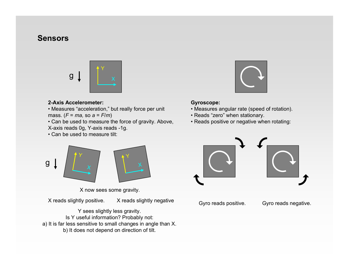
2-Axis Accelerometer:
• Measures “acceleration,” but really force per unit
mass. (F = ma, so a = F/m)
• Can be used to measure the force of gravity. Above,
X-axis reads 0g, Y-axis reads -1g.
• Can be used to measure tilt:
Gyroscope:
• Measures angular rate (speed of rotation).
• Reads “zero” when stationary.
• Reads positive or negative when rotating:
g
Y
X
Y
X
X now sees some gravity.
X reads slightly positive.
X reads slightly negative
Y sees slightly less gravity.
Is Y useful information? Probably not:
a) It is far less sensitive to small changes in angle than X.
b) It does not depend on direction of tilt.
Gyro reads positive.
Gyro reads negative.
�
Reading Values from the Sensors
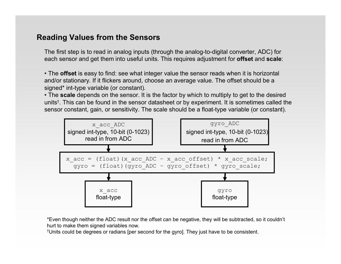
The first step is to read in analog inputs (through the analog-to-digital converter, ADC) for
each sensor and get them into useful units. This requires adjustment for offset and scale:
• The offset is easy to find: see what integer value the sensor reads when it is horizontal
and/or stationary. If it flickers around, choose an average value. The offset should be a
signed* int-type variable (or constant).
• The scale depends on the sensor. It is the factor by which to multiply to get to the desired
units†. This can be found in the sensor datasheet or by experiment. It is sometimes called the
sensor constant, gain, or sensitivity. The scale should be a float-type variable (or constant).
x_acc_ADC
signed int-type, 10-bit (0-1023)
read in from ADC
gyro_ADC
signed int-type, 10-bit (0-1023)
read in from ADC
x_acc = (float)(x_acc_ADC – x_acc_offset) * x_acc_scale;
gyro = (float)(gyro_ADC – gyro_offset) * gyro_scale;
x_acc
float-type
gyro
float-type
*Even though neither the ADC result nor the offset can be negative, they will be subtracted, so it couldn’t
hurt to make them signed variables now.
†Units could be degrees or radians [per second for the gyro]. They just have to be consistent.
�
A bit more about the accelerometer…
If it was necessary to have an estimate of angle for 360º of rotation, having the Y-axis
measurement would be useful, but not necessary. With it, we could use trigonometry to find the
inverse tangent of the two axis readings and calculate the angle. Without it, we can still use sine
or cosine and the X-axis alone to figure out angle, since we know the magnitude of gravity. But
trig kills processor time and is non-linear, so if it can be avoided, it should.
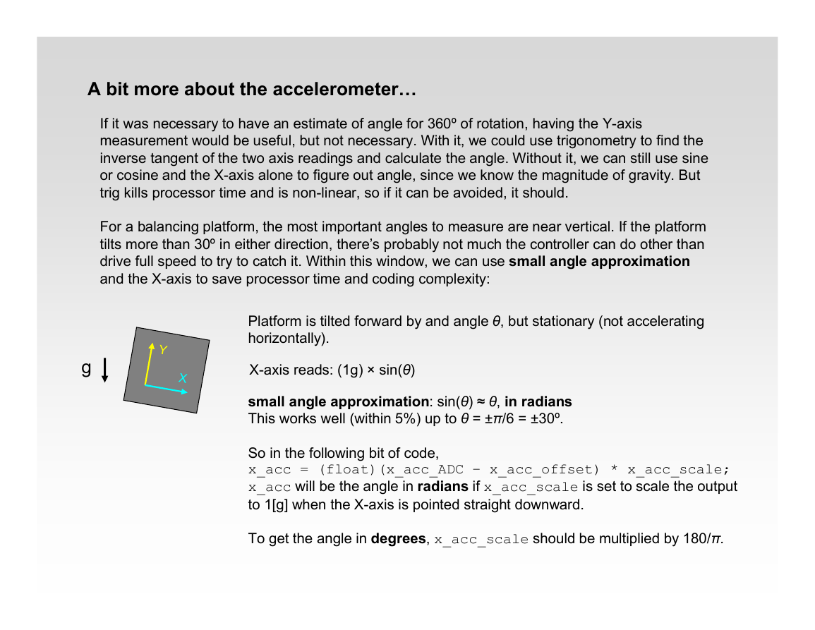
For a balancing platform, the most important angles to measure are near vertical. If the platform
tilts more than 30º in either direction, there’s probably not much the controller can do other than
drive full speed to try to catch it. Within this window, we can use small angle approximation
and the X-axis to save processor time and coding complexity:
g
Y
X
Platform is tilted forward by and angle θ, but stationary (not accelerating
horizontally).
X-axis reads: (1g) × sin(θ)
small angle approximation: sin(θ) ≈ θ, in radians
This works well (within 5%) up to θ = ±π/6 = ±30º.
So in the following bit of code,
x_acc = (float)(x_acc_ADC – x_acc_offset) * x_acc_scale;
x_acc will be the angle in radians if x_acc_scale is set to scale the output
to 1[g] when the X-axis is pointed straight downward.
To get the angle in degrees, x_acc_scale should be multiplied by 180/π.
�
Desired Measurements
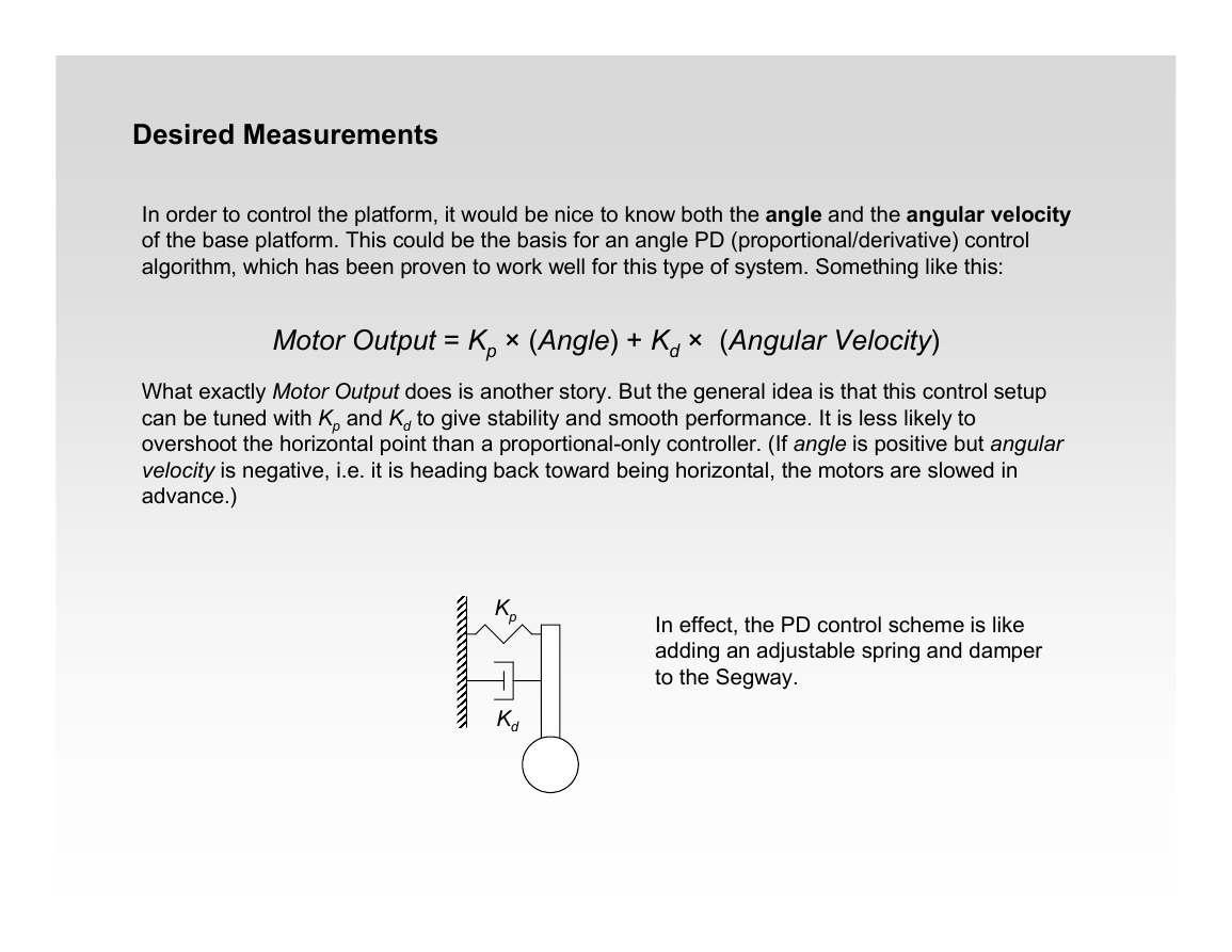
In order to control the platform, it would be nice to know both the angle and the angular velocity
of the base platform. This could be the basis for an angle PD (proportional/derivative) control
algorithm, which has been proven to work well for this type of system. Something like this:
Motor Output = Kp × (Angle) + Kd × (Angular Velocity)
What exactly Motor Output does is another story. But the general idea is that this control setup
can be tuned with Kp and Kd to give stability and smooth performance. It is less likely to
overshoot the horizontal point than a proportional-only controller. (If angle is positive but angular
velocity is negative, i.e. it is heading back toward being horizontal, the motors are slowed in
advance.)
Kp
Kd
In effect, the PD control scheme is like
adding an adjustable spring and damper
to the Segway.
�
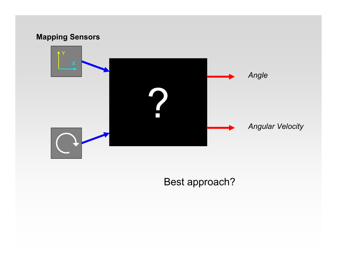
Mapping Sensors
Y
X
Angle
Angular Velocity
Best approach?
�
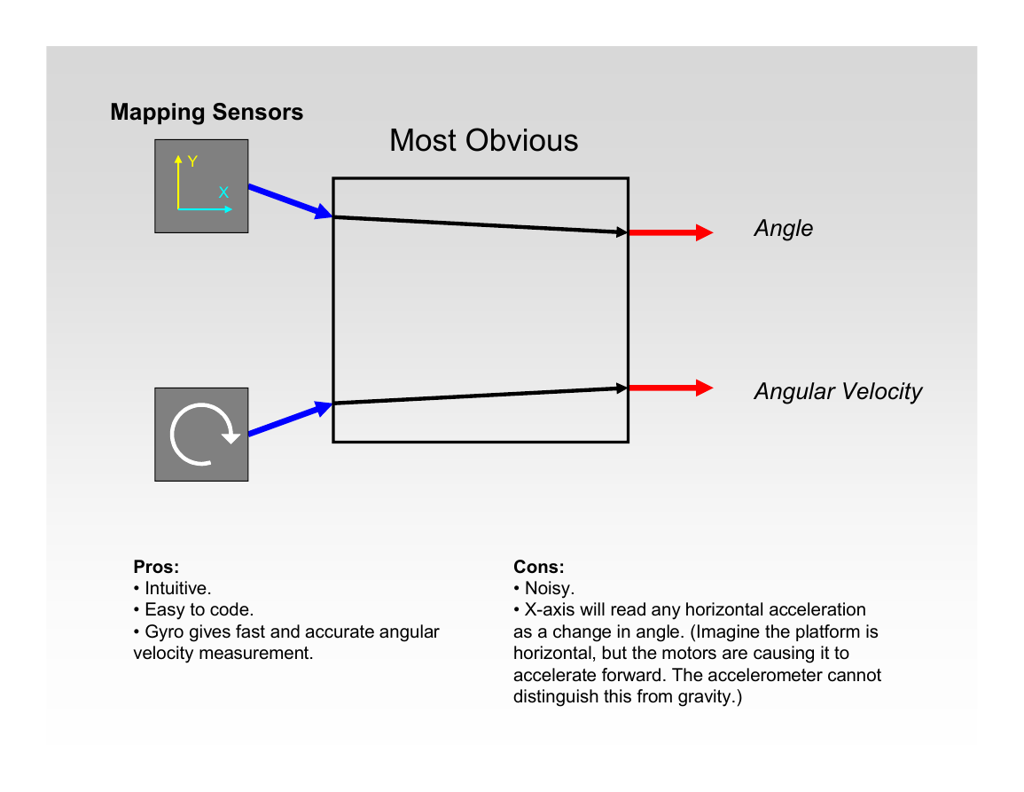
Mapping Sensors
Y
X
Most Obvious
Angle
Angular Velocity
Pros:
• Intuitive.
• Easy to code.
• Gyro gives fast and accurate angular
velocity measurement.
Cons:
• Noisy.
• X-axis will read any horizontal acceleration
as a change in angle. (Imagine the platform is
horizontal, but the motors are causing it to
accelerate forward. The accelerometer cannot
distinguish this from gravity.)
�
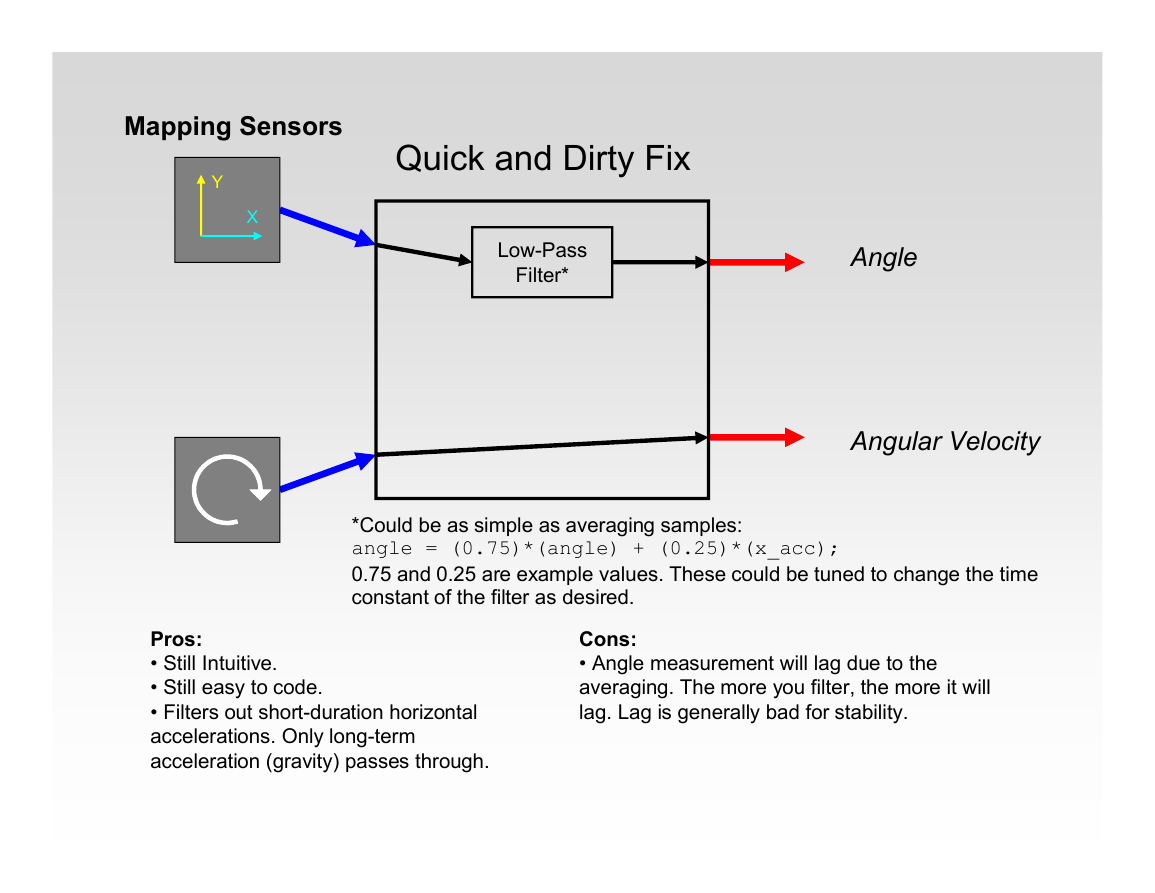
Mapping Sensors
Y
X
Quick and Dirty Fix
Low-Pass
Filter*
Angle
Angular Velocity
*Could be as simple as averaging samples:
angle = (0.75)*(angle) + (0.25)*(x_acc);
0.75 and 0.25 are example values. These could be tuned to change the time
constant of the filter as desired.
Pros:
• Still Intuitive.
• Still easy to code.
• Filters out short-duration horizontal
accelerations. Only long-term
acceleration (gravity) passes through.
Cons:
• Angle measurement will lag due to the
averaging. The more you filter, the more it will
lag. Lag is generally bad for stability.
�

