SPL06-001
Digital pressure sensor
Tel: + 86 536 8525155
Fax: + 86 536 8525000
E- Mail: goertek@goertek.com
Website: http://www.goertekacoustics.com
Address: No.268 Dongfang Road, High-Tech Industry
Development District, Weifang, Shandong, P.R.C
_________________________ ____________________________________________ __
Version 2.0
1 / 31
CONFIDENTIAL�
Restricted
1. Security warning
The information contained in this document is the exclusive property of GoerTek Inc. and should not be
disclosed to any third party without the written consent of GoerTek Inc.
2. Publication history
Version
Date
Description
Author
Approved
1.0
2015.12.18
New design
Wiming
Sammy
2.0
2016.3.14
① Update ○G Marking
② Replace the cover
③ Update peak current
④ Update Marking
instructions
Wiming
Sammy
_________________________ ____________________________________________ __
Version 2.0
2 / 31
CONFIDENTIAL�
Index of Contents
1.
2.
INTRODUCTION ............................................................................................................................................................. 5
TEST CONDITION ........................................................................................................................................................... 6
3. ABSOLUTE MAXIMUM RATINGS .................................................................................................................................... 6
4.
ELECTRICAL CHARACTERISTICS ...................................................................................................................................... 6
5. OPERATION ................................................................................................................................................................... 8
5.1
OPERATING MODES ...................................................................................................................................................... 8
5.2 MEASUREMENT PRECISION AND RATE .......................................................................................................................... 8
5.3
SENSOR INTERFACE ...................................................................................................................................................... 9
INTERRUPT ................................................................................................................................................................... 9
5.4
FIFO OPERATION ......................................................................................................................................................... 9
5.5
5.6
CALIBRATION AND MEASUREMENT COMPENSATION .................................................................................................. 10
How to Calculate Compensated Pressure Values .......................................................................................... 10
How to Calculate Compensated Temperature Values ........................................................................................ 10
Compensation Scale Factors ............................................................................................................................. 10
5.6.1
5.6.2
5.6.3
6. APPLICATIONS ............................................................................................................................................................. 11
6.1 MEASUREMENT SETTINGS AND USE CASE EXAMPLES ................................................................................................ 11
6.2
APPLICATION CIRCUIT EXAMPLE ................................................................................................................................ 12
CALCULATING ABSOLUTE ALTITUDE AND CALCULATING PRESSURE AT SEA LEVEL ...................................................... 13
6.3
7. REGISTER MAP ............................................................................................................................................................ 14
8. REGISTER DESCRIPTION ............................................................................................................................................... 15
8.1
PRESSURE DATA (PRS_BN) ........................................................................................................................................ 15
8.1.1 PRS_B2.................................................................................................................................................................. 15
8.1.2 PRS_B1.................................................................................................................................................................. 15
8.1.3 PRS_B0.................................................................................................................................................................. 15
TEMPERATURE DATA (TMP_TN) ................................................................................................................................ 16
8.2.1 TMP_B2 ................................................................................................................................................................ 16
8.2.2 TMP_B1 ................................................................................................................................................................ 16
8.2.3 TMP_B0 ................................................................................................................................................................ 17
PRESSURE CONFIGURATION (PRS_CFG) .................................................................................................................... 17
TEMPERATURE CONFIGURATION (TMP_CFG) ........................................................................................................... 19
SENSOR OPERATING MODE AND STATUS (MEAS_CFG) ......................................................................................... 20
INTERRUPT AND FIFO CONFIGURATION (CFG_REG) ................................................................................................. 21
INTERRUPT STATUS (INT_STS) .................................................................................................................................. 22
8.2
8.3
8.4
8.5
8.6
8.7
_________________________ ____________________________________________ __
Version 2.0
3 / 31
CONFIDENTIAL�
8.8
FIFO STATUS (FIFO_STS) ......................................................................................................................................... 22
8.9
SOFT RESET AND FIFO FLUSH (RESET)..................................................................................................................... 23
8.10
PRODUCT AND REVISION ID (ID)................................................................................................................................ 23
8.11 CALIBRATION COEFFICIENTS (COEF) ........................................................................................................................ 23
8.12 COEFFICIENT SOURCE ................................................................................................................................................ 24
9. MECHANICAL CHARACTERISTICS ................................................................................................................................. 25
PIN CONFIGURATION ................................................................................................................................................... 25
9.1
OUTLINE DIMENSIONS ................................................................................................................................................ 26
9.2
9.3 MARKING INSTRUCTIONS ............................................................................................................................................... 27
10.
11.
12.
STORAGE AND TRANSPORTATION ........................................................................................................................... 28
SOLDERING RECOMMENDATION ............................................................................................................................. 28
PACKAGE SPECIFICATIONS ....................................................................................................................................... 29
_________________________ ____________________________________________ __
Version 2.0
4 / 31
CONFIDENTIAL�
1. Introduction
The SPL06-001 is a miniaturized Digital Barometric Air Pressure Sensor with a high accuracy and a low current
consumption. The SPL06-001 is both a pressure and a temperature sensor. The pressure sensor element is based on
a capacitive sensing principle which guarantees a high precision during temperature changes. The small package
makes the SPL06-001 ideal for mobile applications and wearable devices.
The SPL06-001‘s internal signal processor converts the output from the pressure and temperature sensor elements
to 24-bit results. Each pressure sensor has been calibrated individually and contains calibration coefficients. The
coefficients are used in the application to convert the measurement results to true pressure and temperature values.
The SPL06-001 has a FIFO that can store the latest 32 measurements. By using the FIFO, the host processor can
remain in a sleep mode for a longer period of time between readouts. This can reduce the overall system power
consumption.
Sensor measurements and calibration coefficients are available through the serial I2C interface.
Key features
Pressure range: 300 ... 1100hPa (+9000m ... -500m relating to sea level)
Temperature Range: -40…+85°C
Supply voltage: 1.7 ... 3.6V (VDD), 1.2 ... 3.6V (VDDIO)
Package: LGA package with metal lid
Small footprint: 2.5mm x 2.0mm; Super-flat: 0.95mm height
Relative accuracy: ±0.06hPa, equiv. to ±0.5 m
Ab solute accuracy: typ. ±1hPa (300 … 1100hPa)
Temperature accuracy: ± 0.5°C.
Pressure temperature sensitivity: < 0.5Pa/K
Measurement time: Typical: 28 ms. Minimum: 3 ms.
Average current consumption: High precision: 60 µA, Low power: 3 µA, Standby: <1 µA.
I2C interface (up to 3.4 MHz), Embedded 24-bit ADC
FIFO: Stores latest 32 pressure or temperature measurements.
Pb-free, halogen-free and RoHS compliant
MSL 1
In- and out-door navigation
Typical applications
Enhancement of GPS navigation (dead-reckoning, slope detection, etc.)
Leisure and sports
Weather forecast
Vertical velocity indication (rise/sink speed)
_________________________ ____________________________________________ __
Version 2.0
5 / 31
CONFIDENTIAL�
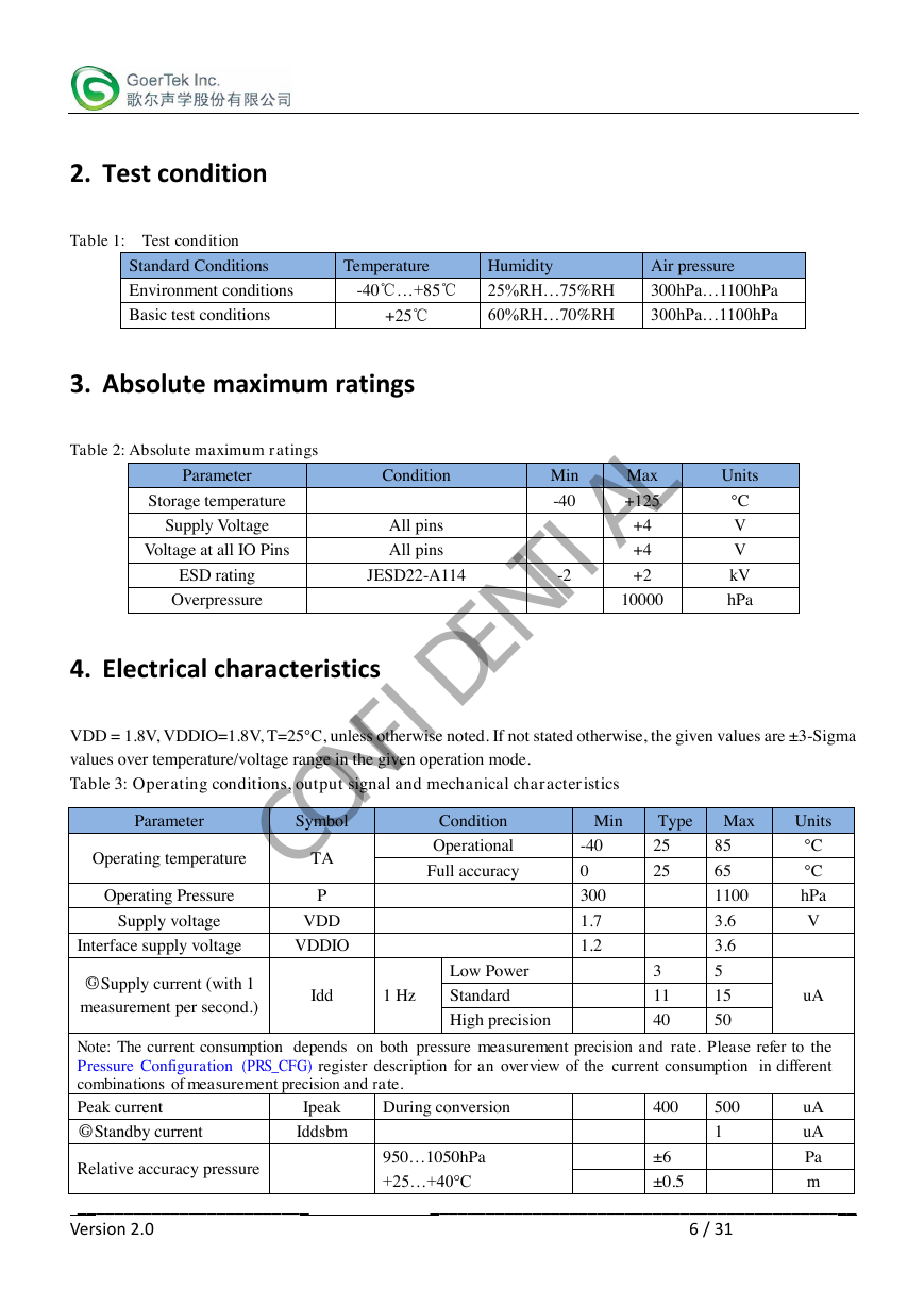
2. Test condition
Table 1: Test condition
Standard Conditions
Temperature
Humidity
Air pressure
Environment conditions
-40℃…+85℃
25%RH…75%RH
300hPa…1100hPa
Basic test conditions
+25℃
60%RH…70%RH
300hPa…1100hPa
3. Absolute maximum ratings
Table 2: Absolute maximum ratings
Parameter
Storage temperature
Supply Voltage
Voltage at all IO Pins
ESD rating
Overpressure
Condition
All pins
All pins
JESD22-A114
Min
-40
-2
Max
+125
+4
+4
+2
10000
Units
°C
V
V
kV
hPa
4. Electrical characteristics
VDD = 1.8V, VDDIO=1.8V, T=25°C, unless otherwise noted. If not stated otherwise, the given values are ±3-Sigma
values over temperature/voltage range in the given operation mode.
Table 3: Operating conditions, output signal and mechanical characteristics
Parameter
Symbol
Operating temperature
Operating Pressure
Supply voltage
TA
P
VDD
Interface supply voltage
VDDIO
Condition
Operational
Full accuracy
○G Supply current (with 1
measurement per second.)
Low Power
Idd
1 Hz
Standard
High precision
Min
Type Max
Units
-40
0
300
1.7
1.2
25
25
3
11
40
85
65
1100
3.6
3.6
5
15
50
°C
°C
hPa
V
uA
Note: The current consumption depends on both pressure measurement precision and rate. Please refer to the
Pressure Configuration (PRS_CFG) register description for an overview of the current consumption in different
combinations of measurement precision and rate.
Peak current
○G Standby current
During conversion
Iddsbm
Ipeak
uA
uA
400
500
1
Relative accuracy pressure
950…1050hPa
+25…+40°C
±6
±0.5
Pa
m
_________________________ ____________________________________________ __
Version 2.0
6 / 31
CONFIDENTIAL�
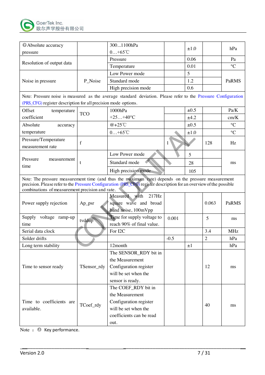
○G Absolute accuracy
pressure
Resolution of output data
300...1100hPa
0…+65℃
Pressure
Temperature
Low Power mode
Noise in pressure
P_Noise
Standard mode
High precision mode
±1.0
0.06
0.01
5
1.2
0.6
hPa
Pa
°C
PaRMS
Note: Pressure noise is measured as the average standard deviation. Please refer to the Pressure Configuration
(PRS_CFG) register description for all precision mode options.
Offset
temperature
coefficient
TCO
Absolute
accuracy
temperature
Pressure/Temperature
measurement rate
Pressure
measurement
time
f
t
1000hPa
+25…+40°C
@+25℃
0…+65℃
Low Power mode
Standard mode
High precision mode
1
±0.5
±4.2
±0.5
±1.0
5
28
105
128
Pa/K
cm/K
°C
°C
Hz
ms
Note: The pressure measurement time (and thus the maximum rate) depends on the pressure measurement
precision. Please refer to the Pressure Configuration (PRS_CFG) register description for an overview of the possible
combinations of measurement precision and rate.
Power supply rejection
Ap_psr
square wave and broad
Measured with 217Hz
±1
0.063
PaRMS
5
3.4
2
ms
MHz
hPa
hPa
12
ms
40
ms
-0.5
Supply voltage ramp-up
time
Serial data clock
Solder drifts
Long term stability
band noise, 100mVpp
tvddup
Time for supply voltage to
0.001
reach 90% of final value.
For I2C
12month
The SENSOR_RDY bit in
the Measurement
Time to sensor ready
TSensor_rdy
Configuration register
will be set when the
sensor is ready.
The COEF_RDY bit in
the Measurement
Configuration register
will be set when the
coefficients can be read
out.
Time to coefficients are
available.
TCoef_rdy
Note :○G Key performance.
_________________________ ____________________________________________ __
Version 2.0
7 / 31
CONFIDENTIAL�
5. Operation
5.1 Operating Modes
The SPL06-001 supports 3 different modes of operation: Standby, Command, and Background mode.
• Standby Mode
- Default mode after power on or reset. No measurements are performed.
- All registers and compensation coefficients are accessible.
• Command Mode
- One temperature or pressure measurement is performed according to the selected precision.
- The sensor will return to Standby Mode when the measurement is finished, and the measurement result
will be available in the data registers.
• Background Mode
- Pressure and/or temperature measurements are performed continuously according to the selected
measurement precision and rate. The temperature measurement is performed immediately after the
pressure measurement.
- The FIFO can be used to store 32 measurement results and minimize the number of times the sensor must
be accessed to read out the results.
Note: Operation mode and measurement type are set in the Sensor Operating Mode and Status (MEAS_CFG) register.
5.2 Measurement Precision and Rate
Different applications require different measurement precision and measurement rates. Some applications, like
weather stations, require lower precision and measurement rates than for instance indoor navigation and sports
applications.
The SPL06-001's measurement precision and rate (in background mode) can be configured to match the
requirements of the application in which it is being used. This reduces current consumption of the sensor and
the system.
In order to achieve a higher precision, the SPL06-001 will read the sensor multiple times (oversampling), and
combine the readings into one result. This increases the current consumption and the measurement time, which
again reduces the maximum measurement rate.
The measurement precision, rate and time is set in the Pressure Configuration (PRS_CFG) and Temperature
Configuration (TMP_CFG) registers. The register descriptions contain information about the current consumption
and the possible combinations of measurement precision, time, and rate.
Please note that the pressure sensor is temperature dependent. Temperature measurements must be made together
with the pressure measurements in order to compensate for the temperature dependency. This reduces the
maximum pressure measurement rate, since: Ratetemperature*Timetemperature + Ratepressure*Timepressure<
1 second. Measurement Settings and Use Case Examples contains a table with examples of combinations of
pressure and temperature precision and rates for different use cases.
_________________________ ____________________________________________ __
Version 2.0
8 / 31
CONFIDENTIAL�
