logo资料库

STM32F1与F4的移植.pdf

第1页 / 共52页
第2页 / 共52页
第3页 / 共52页
第4页 / 共52页
第5页 / 共52页
第6页 / 共52页
第7页 / 共52页
第8页 / 共52页
资料共52页,剩余部分请下载后查看
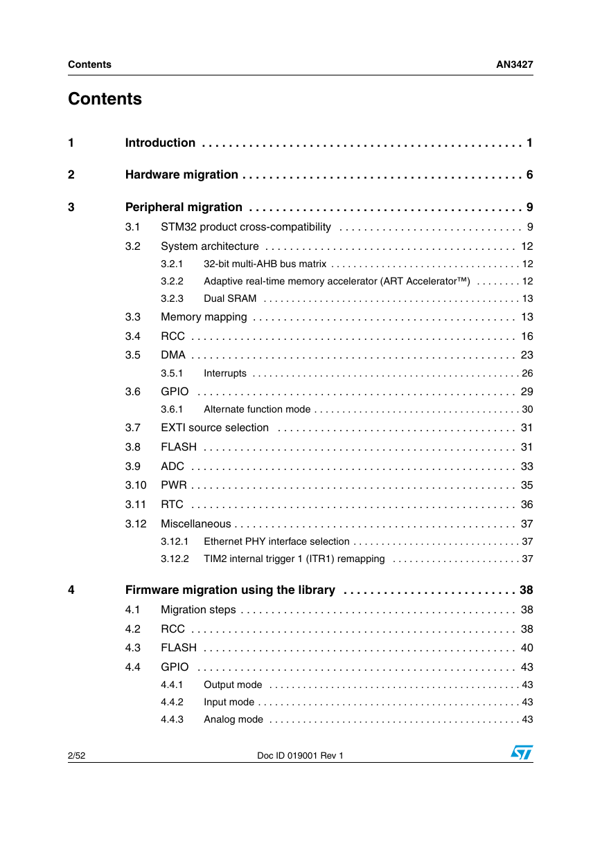
1 Introduction
2 Hardware migration
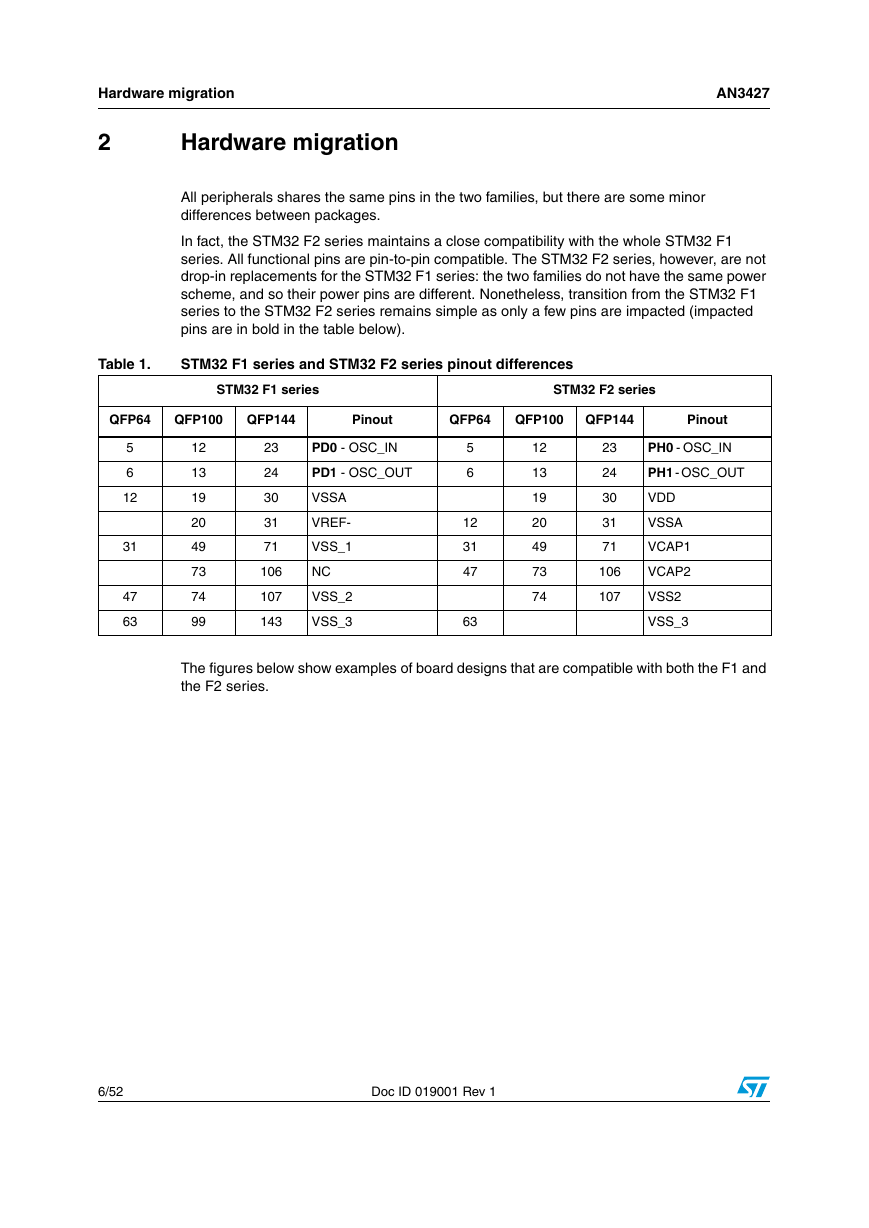
Table 1. STM32 F1 series and STM32 F2 series pinout differences
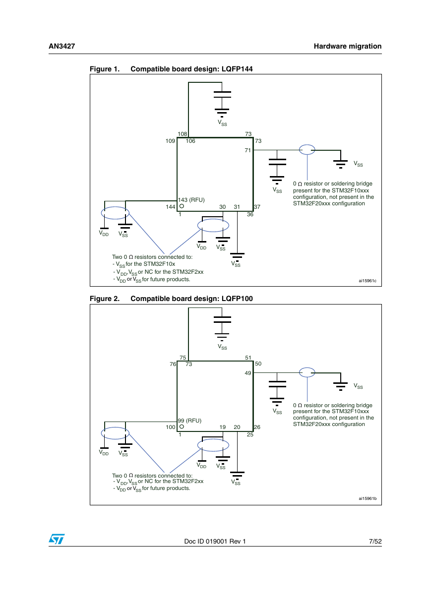
Figure 1. Compatible board design: LQFP144
Figure 2. Compatible board design: LQFP100
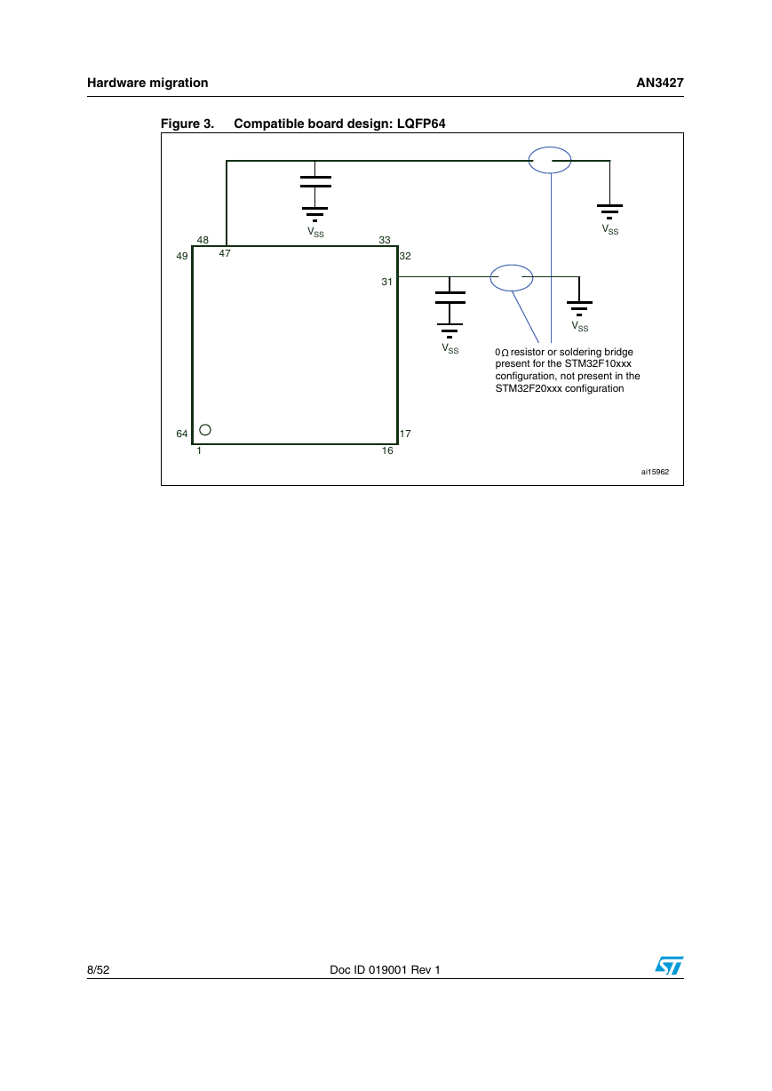
Figure 3. Compatible board design: LQFP64
3 Peripheral migration
3.1 STM32 product cross-compatibility
Table 2. STM32 peripheral compatibility analysis F1 versus F2 series
3.2 System architecture
3.2.1 32-bit multi-AHB bus matrix
Figure 4. STM32 F2 series system architecture
3.2.2 Adaptive real-time memory accelerator (ART Accelerator™)
3.2.3 Dual SRAM
3.3 Memory mapping
Table 3. IP bus mapping differences between STM32 F1 and STM32 F2 series
3.4 RCC
Table 4. RCC differences between STM32 F1 and STM32 F2 series
Table 5. Example of migrating system clock configuration code from F1 to F2 series
Table 6. RCC registers used for peripheral access configuration
3.5 DMA
Table 7. DMA request differences between STM32 F1 series and STM32 F2 series
3.5.1 Interrupts
Table 8. Interrupt vector differences between STM32 F1 series and STM32 F2 series
3.6 GPIO
Table 9. GPIO differences between STM32 F1 series and STM32 F2 series
3.6.1 Alternate function mode
3.7 EXTI source selection
3.8 FLASH
Table 10. FLASH differences between STM32 F1 series and STM32 F2 series
3.9 ADC
Table 11. ADC differences between STM32 F1 series and STM32 F2 series
3.10 PWR
Table 12. PWR differences between STM32 F1 series and STM32 F2 series
3.11 RTC
3.12 Miscellaneous
3.12.1 Ethernet PHY interface selection
3.12.2 TIM2 internal trigger 1 (ITR1) remapping
4 Firmware migration using the library
4.1 Migration steps
4.2 RCC
4.3 FLASH
Table 13. STM32F10x and STM32F2xx FLASH driver API correspondence
4.4 GPIO
4.4.1 Output mode
4.4.2 Input mode
4.4.3 Analog mode
4.4.4 Alternate function mode
4.5 EXTI
4.6 DMA
4.7 ADC
4.8 Backup data registers
4.9 Miscellaneous
4.9.1 Ethernet PHY interface selection
4.9.2 TIM2 internal trigger 1 (ITR1) remapping
5 Revision history
Table 14. Document revision history
AN3427 Application note Migrating a microcontroller application from STM32F1 to STM32F2 series 1 Introduction For designers of STM32 microcontroller applications, it is important to be able to easily replace one microcontroller type by another one in the same product family. Migrating an application to a different microcontroller is often needed, when product requirements grow, putting extra demands on memory size, or increasing the number of I/Os. On the other hand, cost reduction objectives may force you to switch to smaller components and shrink the PCB area. This application note is written to help you and analyze the steps you need to migrate from an existing STM32F1 devices based design to STM32F2 devices. It groups together all the most important information and lists the vital aspects that you need to address. To migrate your application from STM32 F1 series to F2 series, you have to analyze the hardware migration, the peripheral migration and the firmware migration. To benefit fully from the information in this application note, the user should be familiar with the STM32 microcontroller family. Available from www.st.com. ● The STM32F1 family reference manuals (RM0008 and RM0041), the STM32F1 datasheets, and the STM32F1 Flash programming manuals (PM0075, PM0063 and PM0068). The STM32F2 family reference manual (RM0033), the STM32F2 datasheets, and the STM32F2 Flash programming manual (PM0059). ● For an overview of the whole STM32 series and a comparision of the different features of each STM32 product series, please refer to AN3364 'Migration and compatibility guidelines for STM32 microcontroller applications' July 2011 Doc ID 019001 Rev 1 1/52 www.st.com
Contents Contents AN3427 1 2 3 4 Introduction . . . . . . . . . . . . . . . . . . . . . . . . . . . . . . . . . . . . . . . . . . . . . . . . 1 Hardware migration . . . . . . . . . . . . . . . . . . . . . . . . . . . . . . . . . . . . . . . . . . 6 3.3 3.4 3.5 3.6 Peripheral migration . . . . . . . . . . . . . . . . . . . . . . . . . . . . . . . . . . . . . . . . . 9 STM32 product cross-compatibility . . . . . . . . . . . . . . . . . . . . . . . . . . . . . . 9 3.1 System architecture . . . . . . . . . . . . . . . . . . . . . . . . . . . . . . . . . . . . . . . . . 12 3.2 32-bit multi-AHB bus matrix . . . . . . . . . . . . . . . . . . . . . . . . . . . . . . . . . . 12 3.2.1 3.2.2 Adaptive real-time memory accelerator (ART Accelerator™) . . . . . . . . 12 3.2.3 Dual SRAM . . . . . . . . . . . . . . . . . . . . . . . . . . . . . . . . . . . . . . . . . . . . . . 13 Memory mapping . . . . . . . . . . . . . . . . . . . . . . . . . . . . . . . . . . . . . . . . . . . 13 RCC . . . . . . . . . . . . . . . . . . . . . . . . . . . . . . . . . . . . . . . . . . . . . . . . . . . . . 16 DMA . . . . . . . . . . . . . . . . . . . . . . . . . . . . . . . . . . . . . . . . . . . . . . . . . . . . . 23 3.5.1 Interrupts . . . . . . . . . . . . . . . . . . . . . . . . . . . . . . . . . . . . . . . . . . . . . . . . 26 GPIO . . . . . . . . . . . . . . . . . . . . . . . . . . . . . . . . . . . . . . . . . . . . . . . . . . . . 29 3.6.1 Alternate function mode . . . . . . . . . . . . . . . . . . . . . . . . . . . . . . . . . . . . . 30 EXTI source selection . . . . . . . . . . . . . . . . . . . . . . . . . . . . . . . . . . . . . . . 31 3.7 FLASH . . . . . . . . . . . . . . . . . . . . . . . . . . . . . . . . . . . . . . . . . . . . . . . . . . . 31 3.8 3.9 ADC . . . . . . . . . . . . . . . . . . . . . . . . . . . . . . . . . . . . . . . . . . . . . . . . . . . . . 33 3.10 PWR . . . . . . . . . . . . . . . . . . . . . . . . . . . . . . . . . . . . . . . . . . . . . . . . . . . . . 35 3.11 RTC . . . . . . . . . . . . . . . . . . . . . . . . . . . . . . . . . . . . . . . . . . . . . . . . . . . . . 36 3.12 Miscellaneous . . . . . . . . . . . . . . . . . . . . . . . . . . . . . . . . . . . . . . . . . . . . . . 37 Ethernet PHY interface selection . . . . . . . . . . . . . . . . . . . . . . . . . . . . . . 37 TIM2 internal trigger 1 (ITR1) remapping . . . . . . . . . . . . . . . . . . . . . . . 37 3.12.1 3.12.2 Firmware migration using the library . . . . . . . . . . . . . . . . . . . . . . . . . . 38 Migration steps . . . . . . . . . . . . . . . . . . . . . . . . . . . . . . . . . . . . . . . . . . . . . 38 4.1 4.2 RCC . . . . . . . . . . . . . . . . . . . . . . . . . . . . . . . . . . . . . . . . . . . . . . . . . . . . . 38 FLASH . . . . . . . . . . . . . . . . . . . . . . . . . . . . . . . . . . . . . . . . . . . . . . . . . . . 40 4.3 GPIO . . . . . . . . . . . . . . . . . . . . . . . . . . . . . . . . . . . . . . . . . . . . . . . . . . . . 43 4.4 4.4.1 Output mode . . . . . . . . . . . . . . . . . . . . . . . . . . . . . . . . . . . . . . . . . . . . . 43 Input mode . . . . . . . . . . . . . . . . . . . . . . . . . . . . . . . . . . . . . . . . . . . . . . . 43 4.4.2 4.4.3 Analog mode . . . . . . . . . . . . . . . . . . . . . . . . . . . . . . . . . . . . . . . . . . . . . 43 2/52 Doc ID 019001 Rev 1
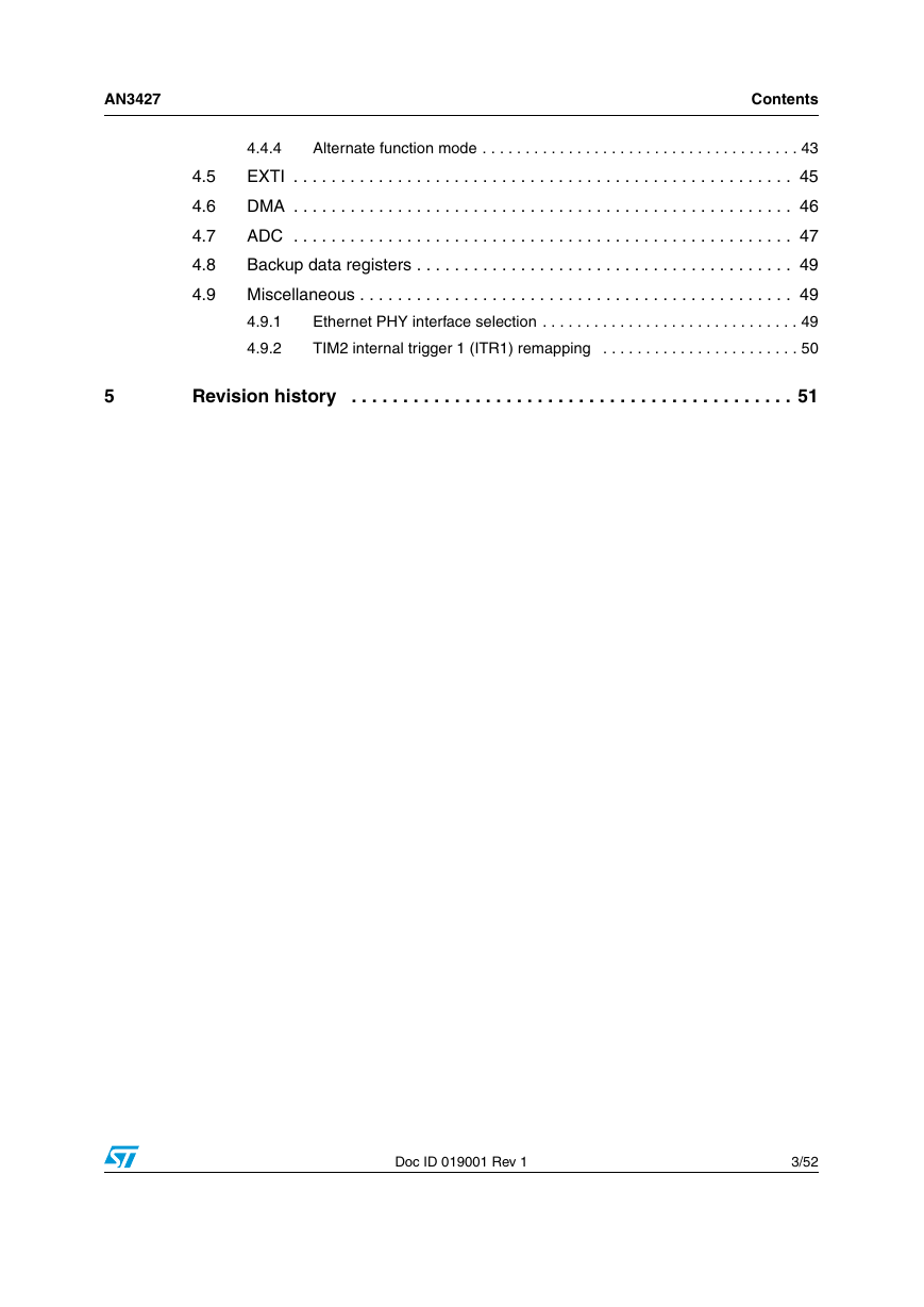
AN3427 Contents 4.5 4.6 4.7 4.8 4.9 4.4.4 Alternate function mode . . . . . . . . . . . . . . . . . . . . . . . . . . . . . . . . . . . . . 43 EXTI . . . . . . . . . . . . . . . . . . . . . . . . . . . . . . . . . . . . . . . . . . . . . . . . . . . . . 45 DMA . . . . . . . . . . . . . . . . . . . . . . . . . . . . . . . . . . . . . . . . . . . . . . . . . . . . . 46 ADC . . . . . . . . . . . . . . . . . . . . . . . . . . . . . . . . . . . . . . . . . . . . . . . . . . . . . 47 Backup data registers . . . . . . . . . . . . . . . . . . . . . . . . . . . . . . . . . . . . . . . . 49 Miscellaneous . . . . . . . . . . . . . . . . . . . . . . . . . . . . . . . . . . . . . . . . . . . . . . 49 Ethernet PHY interface selection . . . . . . . . . . . . . . . . . . . . . . . . . . . . . . 49 4.9.1 4.9.2 TIM2 internal trigger 1 (ITR1) remapping . . . . . . . . . . . . . . . . . . . . . . . 50 5 Revision history . . . . . . . . . . . . . . . . . . . . . . . . . . . . . . . . . . . . . . . . . . . 51 Doc ID 019001 Rev 1 3/52
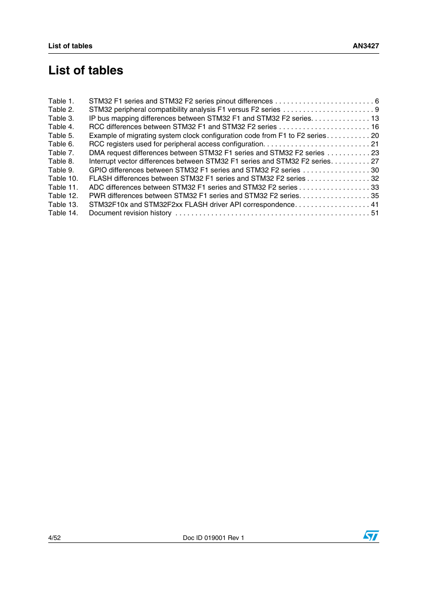
List of tables List of tables AN3427 Table 1. Table 2. Table 3. Table 4. Table 5. Table 6. Table 7. Table 8. Table 9. Table 10. Table 11. Table 12. Table 13. Table 14. STM32 F1 series and STM32 F2 series pinout differences . . . . . . . . . . . . . . . . . . . . . . . . . 6 STM32 peripheral compatibility analysis F1 versus F2 series . . . . . . . . . . . . . . . . . . . . . . . 9 IP bus mapping differences between STM32 F1 and STM32 F2 series. . . . . . . . . . . . . . . 13 RCC differences between STM32 F1 and STM32 F2 series . . . . . . . . . . . . . . . . . . . . . . . 16 Example of migrating system clock configuration code from F1 to F2 series . . . . . . . . . . . 20 RCC registers used for peripheral access configuration. . . . . . . . . . . . . . . . . . . . . . . . . . . 21 DMA request differences between STM32 F1 series and STM32 F2 series . . . . . . . . . . . 23 Interrupt vector differences between STM32 F1 series and STM32 F2 series. . . . . . . . . . 27 GPIO differences between STM32 F1 series and STM32 F2 series . . . . . . . . . . . . . . . . . 30 FLASH differences between STM32 F1 series and STM32 F2 series . . . . . . . . . . . . . . . . 32 ADC differences between STM32 F1 series and STM32 F2 series . . . . . . . . . . . . . . . . . . 33 PWR differences between STM32 F1 series and STM32 F2 series. . . . . . . . . . . . . . . . . . 35 STM32F10x and STM32F2xx FLASH driver API correspondence. . . . . . . . . . . . . . . . . . . 41 Document revision history . . . . . . . . . . . . . . . . . . . . . . . . . . . . . . . . . . . . . . . . . . . . . . . . . 51 4/52 Doc ID 019001 Rev 1
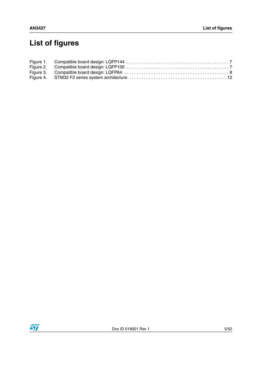
AN3427 List of figures List of figures Figure 1. Figure 2. Figure 3. Figure 4. Compatible board design: LQFP144 . . . . . . . . . . . . . . . . . . . . . . . . . . . . . . . . . . . . . . . . . . 7 Compatible board design: LQFP100 . . . . . . . . . . . . . . . . . . . . . . . . . . . . . . . . . . . . . . . . . . 7 Compatible board design: LQFP64 . . . . . . . . . . . . . . . . . . . . . . . . . . . . . . . . . . . . . . . . . . . 8 STM32 F2 series system architecture . . . . . . . . . . . . . . . . . . . . . . . . . . . . . . . . . . . . . . . . 12 Doc ID 019001 Rev 1 5/52
Hardware migration AN3427 2 Hardware migration All peripherals shares the same pins in the two families, but there are some minor differences between packages. In fact, the STM32 F2 series maintains a close compatibility with the whole STM32 F1 series. All functional pins are pin-to-pin compatible. The STM32 F2 series, however, are not drop-in replacements for the STM32 F1 series: the two families do not have the same power scheme, and so their power pins are different. Nonetheless, transition from the STM32 F1 series to the STM32 F2 series remains simple as only a few pins are impacted (impacted pins are in bold in the table below). Table 1. STM32 F1 series and STM32 F2 series pinout differences STM32 F1 series STM32 F2 series QFP64 QFP100 QFP144 Pinout QFP64 QFP100 QFP144 Pinout 5 6 12 31 47 63 12 13 19 20 49 73 74 99 23 24 30 31 71 106 107 143 PD0 - OSC_IN PD1 - OSC_OUT VSSA VREF- VSS_1 NC VSS_2 VSS_3 5 6 12 31 47 63 12 13 19 20 49 73 74 23 24 30 31 71 106 107 PH0 - OSC_IN PH1 - OSC_OUT VDD VSSA VCAP1 VCAP2 VSS2 VSS_3 The figures below show examples of board designs that are compatible with both the F1 and the F2 series. 6/52 Doc ID 019001 Rev 1
AN3427 Hardware migration Figure 1. Compatible board design: LQFP144 Figure 2. Compatible board design: LQFP100 Doc ID 019001 Rev 1 7/52
Hardware migration AN3427 Figure 3. Compatible board design: LQFP64 8/52 Doc ID 019001 Rev 1
分享到:
收藏