CHAPTER 2
TRANSMISSION FUNDAMENTALS
AAANNNSSSWWWEEERRRSSS TTTOOO QQQUUUEEESSSTTTIIIOOONNNSSS
2.1 A continuous or analog signal is one in which the signal intensity varies in a
smooth fashion over time while a discrete or digital signal is one in which the signal
intensity maintains one of a finite number of constant levels for some period of time
and then changes to another constant level.
2.2 Amplitude, frequency, and phase are three important characteristics of a periodic
signal.
2.3 2π radians.
2.4 The relationship is λf = v, where λ is the wavelength, f is the frequency, and v is the
speed at which the signal is traveling.
2.5 The spectrum of a signal consists of the frequencies it contains; the bandwidth of a
signal is the width of the spectrum.
2.6 Attenuation is the gradual weakening of a signal over distance.
2.7 The rate at which data can be transmitted over a given communication path, or
channel, under given conditions, is referred to as the channel capacity.
2.8 Bandwidth, noise, and error rate affect channel capacity.
2.9 With guided media, the electromagnetic waves are guided along an enclosed
physical path, whereas unguided media provide a means for transmitting
electromagnetic waves through space, air, or water, but do not guide them.
2.10 Point-to-point microwave transmission has a high data rate and less attenuation
than twisted pair or coaxial cable. It is affected by rainfall, however, especially
above 10 GHz. It is also requires line of sight and is subject to interference from
other microwave transmission, which can be intense in some places.
2.11 Direct broadcast transmission is a technique in which satellite video signals are
transmitted directly to the home for continuous operation.
�
2.12 A satellite must use different uplink and downlink frequencies for continuous
operation in order to avoid interference.
2.13 Broadcast is omnidirectional, does not require dish shaped antennas, and the
antennas do not have to be rigidly mounted in precise alignment.
2.14 Multiplexing is cost-effective because the higher the data rate, the more
cost-effective the transmission facility.
2.15 Interference is avoided under frequency division multiplexing by the use of guard
bands, which are unused portions of the frequency spectrum between subchannels.
2.16 A synchronous time division multiplexer interleaves bits from each signal and
takes turns transmitting bits from each of the signals in a round-robin fashion.
AAANNNSSSWWWEEERRRSSS TTTOOO PPPRRROOOBBBLLLEEEMMMSSS
b. sin (2πft) + sin (2πft – π) = 0.
2.1 Period = 1/1000 = 0.001 s = 1 ms.
2.2 a. sin (2πft – π) + sin (2πft + π) = 2 sin (2πft + π) or 2 sin (2πft – π) or - 2 sin (2πft)
2.3
N
F
D
W 1.25
33
33
22
C
264
44
D
297
1.11
44
F
352
0.93
55
G
396
0.83
33
A
440
0.75
E
330
B
495
0.67
1
C
528
0.63
N = note; F = frequency (Hz); D = frequency difference; W = wavelength (m)
2.4 2 sin(4πt + π); A = 2, f = 2, φ = π
2.5 (1 + 0.1 cos 5t) cos 100t = cos 100t + 0.1 cos 5t cos 100t. From the trigonometric
identity cos a cos b = (1/2)(cos(a + b) + cos(a – b)), this equation can be rewritten as
the linear combination of three sinusoids:
cos 100t + 0.05 cos 105t + 0.05 cos 95t
2.6 We have cos2x = cos x cos x = (1/2)(cos(2x) + cos(0)) = (1/2)(cos(2x) + 1). Then:
f(t) = (10 cos t)2 = 100 cos2t = 50 + 50 cos(2t). The period of cos(2t) is π and therefore
the period of f(t) is π.
2.7 If f1(t) is periodic with period X, then f1(t) = f1(t +X) = f1(t +nX) where n is an integer
and X is the smallest value such that f1(t) = f1(t +X). Similarly, f2(t) = f2(t +Y) = f2(t +
-2-
�
mY). We have f(t) = f1(t) + f2(t). If f(t) is periodic with period Z, then f(t) = f(t + Z).
Therefore f1(t) + f2(t) = f1(t + Z) + f2(t + Z). This last equation is satisfied if f1(t) = f1(t
+ Z) and f2(t) = f2(t + Z). This leads to the condition Z = nX = mY for some integers
n and m. We can rewrite this last as (n/m) = (Y/X). We can therefore conclude that
if the ratio (Y/X) is a rational number, then f(t) is periodic.
Therefore, SNR = 100.3
C = 300 log2 (1 + 100.3) = 300 log2 (2.995) = 474 bps
2.8 The signal would be a low-amplitude, rapidly changing waveform.
2.9 Using Shannon's equation: C = B log2 (1 + SNR)
We have W = 300 Hz (SNR)dB = 3
2.10 Using Nyquist's equation: C = 2B log2M
2.11 Nyquist analyzed the theoretical capacity of a noiseless channel; therefore, in that
case, the signaling rate is limited solely by channel bandwidth. Shannon addressed
the question of what signaling rate can be achieved over a channel with a given
bandwidth, a given signal power, and in the presence of noise.
We have C = 9600 bps
a. log2M = 4, because a signal element encodes a 4-bit word
b. 9600 = 2B × 8, and B = 600 Hz
Therefore, C = 9600 = 2B × 4, and
B = 1200 Hz
2.12 a. Using Shannon’s formula: C = 3000 log2 (1+400000) = 56 Kbps
b. Due to the fact there is a distortion level (as well as other potentially
detrimental impacts to the rated capacity, the actual maximum will be
somewhat degraded from the theoretical maximum. A discussion of these
relevant impacts should be included and a qualitative value discussed.
2.13 C = B log2 (1 + SNR)
2.14 From Equation 2.1, we have LdB = 20 log (4πd/λ) = 20 log (4πdf/v), where λf = v
20 × 106 = 3 × 10⁶ × log2(1 + SNR)
log2(1 + SNR) = 6.67
1 + SNR = 102
SNR = 101
(see Question 2.4). If we double either d or f, we add a term 20 log(2), which is
approximately 6 dB.
2.15
-3-
�
8
0.16
6.3
9
0.125
8.0
10
0.1
10
Decibels
Losses
Gains
1
0.8
1.25
2
0.63
1.6
3
0.5
2
4
0.4
2.5
5
0.32
3.2
6
0.25
4.0
7
0.2
5.0
2.16 For a voltage ratio, we have
2.17 Power (dBW) = 10 log (Power/1W) = 10 log20 = 13 dBW
NdB = 30 = 20 log(V2/V1)
V2/V1 = 1030/20 = 101.5 = 31.6
CHAPTER 5
ANTENNAS AND PROPAGATION
AAANNNSSSWWWEEERRRSSS TTTOOO QQQUUUEEESSSTTTIIIOOONNNSSS
5.1 The two functions of an antenna are: (1) For transmission of a signal, radio-
frequency electrical energy from the transmitter is converted into electromagnetic
energy by the antenna and radiated into the surrounding environment (atmosphere,
space, water); (2) for reception of a signal, electromagnetic energy impinging on the
antenna is converted into radio-frequency electrical energy and fed into the receiver.
5.2 An isotropic antenna is a point in space that radiates power in all directions
equally.
5.3 A radiation pattern is a graphical representation of the radiation properties of an
antenna as a function of space coordinates.
5.4 A parabolic antenna creates, in theory, a parallel beam without dispersion. In
practice, there will be some beam spread. Nevertheless, it produces a highly
focused, directional beam.
5.5 Effective area and wavelength.
5.6 Free space loss.
5.7 Thermal noise is due to thermal agitation of electrons. Intermodulation noise
produces signals at a frequency that is the sum or difference of the two original
frequencies or multiples of those frequencies. Crosstalk is the unwanted coupling
between signal paths. Impulse noise is noncontinuous, consisting of irregular
pulses or noise spikes of short duration and of relatively high amplitude.
-4-
�
5.8 Refraction is the bending of a radio beam caused by changes in the speed of
propagation at a point of change in the medium.
5.9 The term fading refers to the time variation of received signal power caused by
changes in the transmission medium or path(s).
5.10 Diffraction occurs at the edge of an impenetrable body that is large compared to
the wavelength of the radio wave. The edge in effect become a source and waves
radiate in different directions from the edge, allowing a beam to bend around an
obstacle. If the size of an obstacle is on the order of the wavelength of the signal or
less, scattering occurs. An incoming signal is scattered into several weaker
outgoing signals in unpredictable directions.
5.11 Fast fading refers to changes in signal strength between a transmitter and receiver
as the distance between the two changes by a small distance of about one-half a
wavelength. Slow fading refers to changes in signal strength between a
transmitter and receiver as the distance between the two changes by a larger
distance, well in excess of a wavelength.
5.12 Flat fading, or nonselective fading, is that type of fading in which all frequency
components of the received signal fluctuate in the same proportions
simultaneously. Selective fading affects unequally the different spectral
components of a radio signal.
5.13 Space diversity involves the physical transmission path and typical refers to the
use of multiple transmitting or receiving antennas. With frequency diversity, the
signal is spread out over a larger frequency bandwidth or carried on multiple
frequency carriers. Time diversity techniques aim to spread the data out over time
so that a noise burst affects fewer bits.
AAANNNSSSWWWEEERRRSSS TTTOOO PPPRRROOOBBBLLLEEEMMMSSS
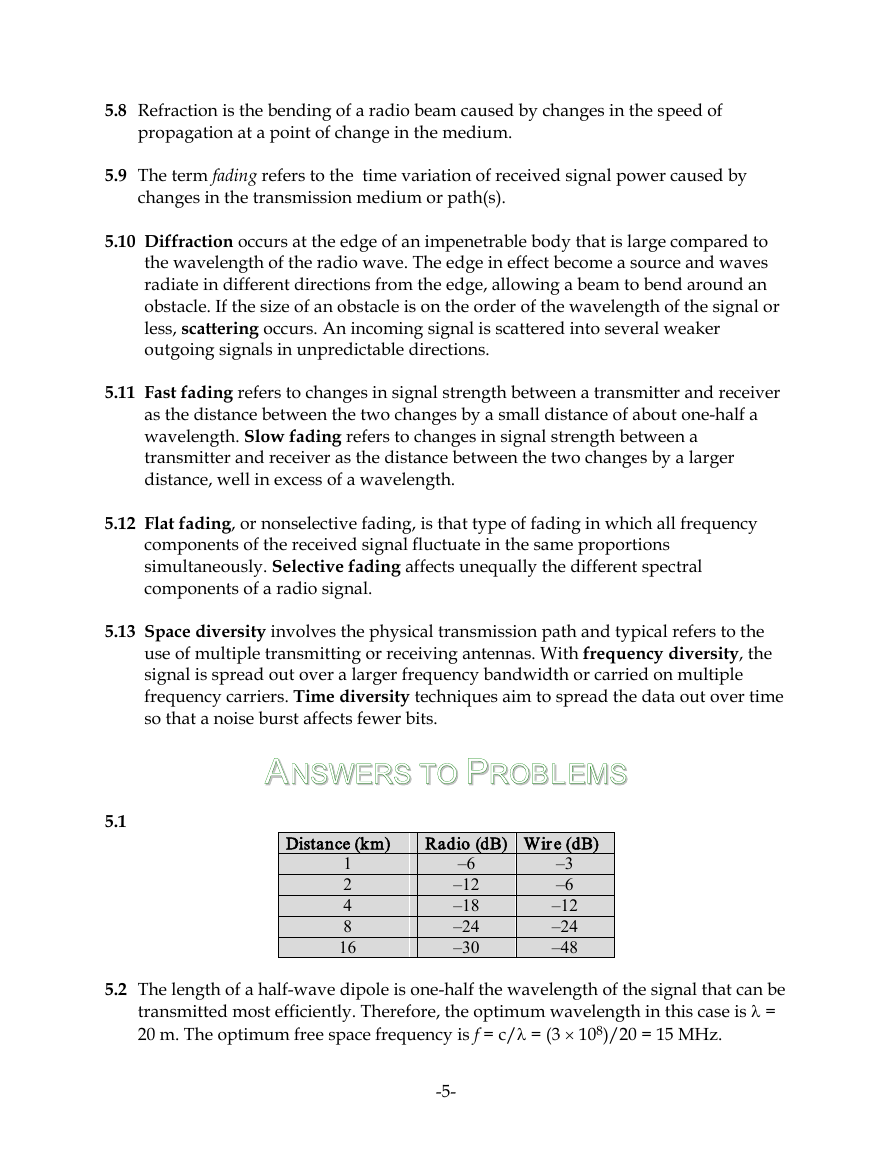
Distance (km)
Radio (dB) Wire (dB)
1
2
4
8
16
–6
–12
–18
–24
–30
–3
–6
–12
–24
–48
5.1
5.2 The length of a half-wave dipole is one-half the wavelength of the signal that can be
transmitted most efficiently. Therefore, the optimum wavelength in this case is λ =
20 m. The optimum free space frequency is f = c/λ = (3 × 10⁸)/20 = 15 MHz.
-5-
�
5.3 We have λf = c; in this case λ × 30 = 3 × 10⁸ m/sec, which yields a wavelength of
10,000 km. Half of that is 5,000 km which is comparable to the east-to-west
dimension of the continental U.S. While an antenna this size is impractical, the U.S.
Defense Department has considered using large parts of Wisconsin and Michigan
to make an antenna many kilometers in diameter.
f = c/λ = (3 × 10⁸ m/sec)/(2 m) = 150 MHz.
λ/2 = 500 km.
b. The carrier frequency corresponding to λ/2 = 1 m is given by:
5.4 a. Using λf = c, we have λ = (3 × 10⁸ m/sec)/(300 Hz) = 1,000 km, so that
5.5 λ = 2 × 2.5 × 10–3 m = 5 × 10⁻³ m
5.6 a. First, take the derivative of both sides of the equation y2 = 2px:
f = c/λ = (3 × 10⁸ m/sec)/( 5 × 10⁻³ m) = 6 × 10¹⁰ Hz = 60 GHz
dy
dx
y2 = dy
dx
2px(
); 2ydy
dx
= 2p; dy
dx
= p
y
Therefore tan β = (p/y1).
b. The slope of PF is (y1 – 0)/(x1 – (p/2)). Therefore:
tanα=
− p
y1
x1 − p
y1
2
p
1 + y1
x1 − p
y1
2
=
2 − px1 + 1
y1
2
x1y1 − 1
2
py1 + py1
p2
Because y1
2 = 2px1, this simplifies to tan α = (p/y1).
5.7
Antenna
Isotropic
Infinitesimal
dipole or loop
Half-wave
dipole
Horn
Parabolic
Turnstile
λ = 30 cm
Effective area (m2)
0.007
0.011
0.012
2.54
1.76
0.008
Gain
1
1.5
1.64
349
244
1.15
-6-
λ = 3 mm
Effective area (m2)
7.2 × 10⁻⁷
1.1 × 10⁻⁶
1.2 × 10⁻⁶
2.54
1.76
8.2 × 10⁻⁷
Gain
1
1.5
1.64
3.5 × 10⁶
2.4 × 10⁶
1.15
�
= 20 log(fMHz) +20 log (dkm) + 32.44
PowerdBm = 10 log (PowermW) = 10 log (50,000) = 47 dBm
Source: [THUR00]
= [(1) (2) (2) (3 × 10⁸)2]/[(16) (π)2 (3 × 10⁸)2 (104)2] = 0.76 × 10⁻⁹ W
LdB = 20 log(900 × 106) +20 log (100) – 147.56 = 120 + 59.08 +40 – 147.56 = 71.52
Therefore, received power in dBm = 47 – 71.52 = –24.52 dBm
b. Using Equation (5.2),
c LdB = 120 + 59.08 +80 – 147.56 =111.52; Pr,dBm = 47 – 111.52 = –64.52 dBm
d The antenna gain results in an increase of 3 dB, so that Pr,dBm = –61.52 dBm
Source: [RAPP02]
5.8 LdB = 20 log(fMHz) + 120 +20 log (dkm) + 60 – 147.56
5.9 We have Pr = [(Pt) (Gt) (Gr) (c)2]/(4πfd)2
5.10 a. From Appendix 2A, PowerdBW = 10 log (PowerW) = 10 log (50) = 17 dBW
5.11 a. From Table 5.2, G = 7A/λ2 = 7Af2/c2 = (7×π×(0.6)2×(2×109)2]/(3×108)2 = 351.85
5.12 From Equation 2.2, the ratio of transmitted power to received power is
GdB = 25.46 dB
b. 0.1 W x 351.85 = 35.185 W
c. Use LdB = 20 log (4π) + 20 log (d) + 20 log (f) – 20 log (c) – 10 log(Gr) – 10 log (Gt)
LdB = 21.98 + 87.6 + 186.02 – 169.54 – 25.46 – 25.46 = 75.14 dB
The transmitter power, in dBm is 10 log (100) = 20.
The available received signal power is 20 – 75.14 = –55.14 dBm
Pt/Pr = (4πd/λ)2
If we double the frequency, we halve λ, or if we double the distance, we double d,
so the new ratio for either of these events is:
Pt/Pr2 = (8πd/λ)2
Therefore:
10 log (Pr/Pr2) = 10 log (22) = 6 dB
5.13
-7-
�
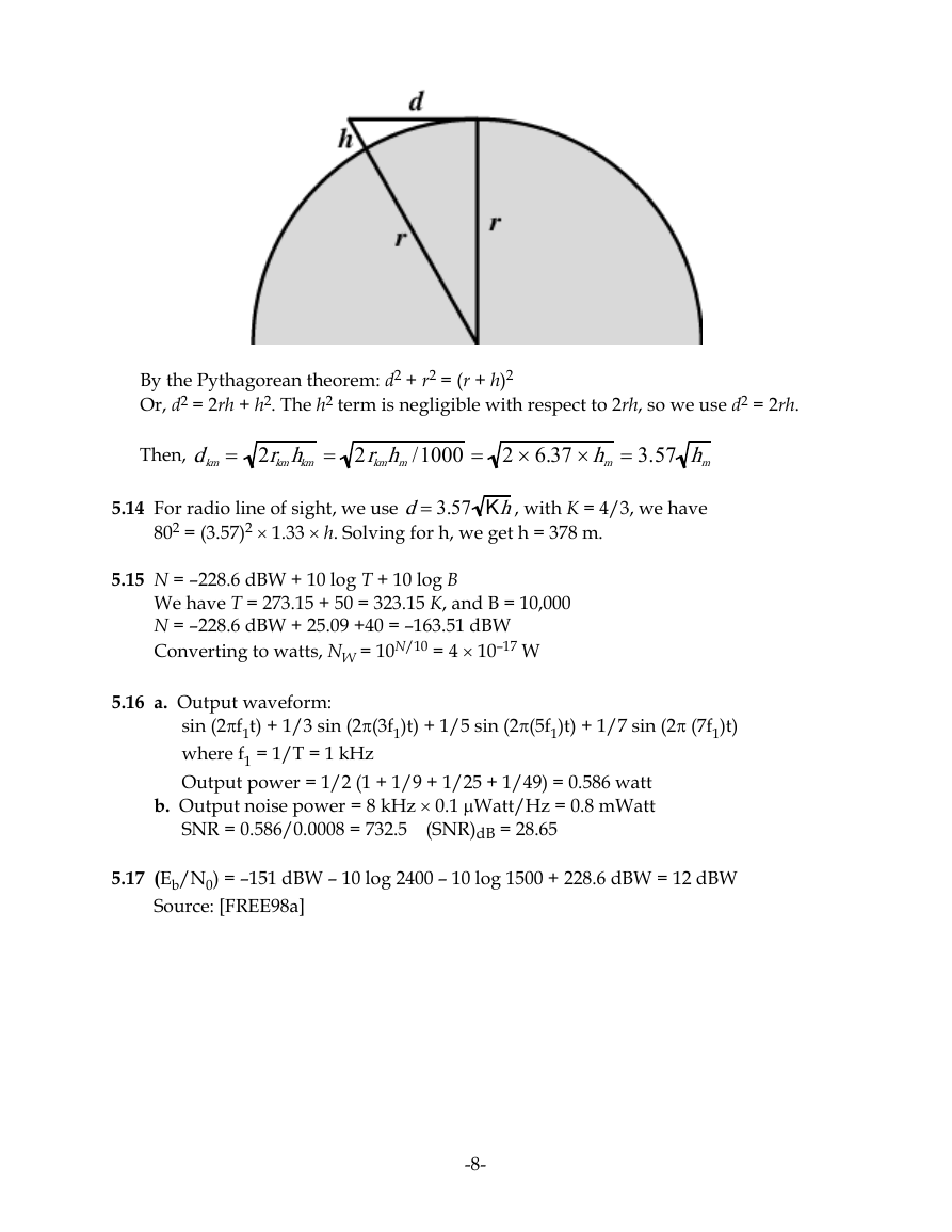
Then, dkm = 2rkmhkm = 2rkmhm/1000 = 2 × 6.37 ×hm = 3.57 hm
802 = (3.57)2 × 1.33 × h. Solving for h, we get h = 378 m.
sin (2πf1t) + 1/3 sin (2π(3f1)t) + 1/5 sin (2π(5f1)t) + 1/7 sin (2π (7f1)t)
By the Pythagorean theorem: d2 + r2 = (r + h)2
We have T = 273.15 + 50 = 323.15 K, and B = 10,000
N = –228.6 dBW + 25.09 +40 = –163.51 dBW
Converting to watts, NW = 10N/10 = 4 × 10–17 W
Or, d2 = 2rh + h2. The h2 term is negligible with respect to 2rh, so we use d2 = 2rh.
5.14 For radio line of sight, we use d= 3.57 Kh, with K = 4/3, we have
5.15 N = –228.6 dBW + 10 log T + 10 log B
5.16 a. Output waveform:
5.17 (Eb/N0) = –151 dBW – 10 log 2400 – 10 log 1500 + 228.6 dBW = 12 dBW
where f1 = 1/T = 1 kHz
Output power = 1/2 (1 + 1/9 + 1/25 + 1/49) = 0.586 watt
b. Output noise power = 8 kHz × 0.1 µWatt/Hz = 0.8 mWatt
SNR = 0.586/0.0008 = 732.5 (SNR)dB = 28.65
Source: [FREE98a]
-8-
�


 2023年江西萍乡中考道德与法治真题及答案.doc
 2012年重庆南川中考生物真题及答案.doc
 2013年江西师范大学地理学综合及文艺理论基础考研真题.doc
 2020年四川甘孜小升初语文真题及答案I卷.doc
 2020年注册岩土工程师专业基础考试真题及答案.doc
 2023-2024学年福建省厦门市九年级上学期数学月考试题及答案.doc
 2021-2022学年辽宁省沈阳市大东区九年级上学期语文期末试题及答案.doc
 2022-2023学年北京东城区初三第一学期物理期末试卷及答案.doc
 2018上半年江西教师资格初中地理学科知识与教学能力真题及答案.doc
 2012年河北国家公务员申论考试真题及答案-省级.doc
 2020-2021学年江苏省扬州市江都区邵樊片九年级上学期数学第一次质量检测试题及答案.doc
 2022下半年黑龙江教师资格证中学综合素质真题及答案.doc