Understanding And Using
PMBus™ Data Formats
Robert V. White
bob.white@ieee.org
Daniel Durant
dan.durant@artesyn.com
Artesyn Technologies
1401 West 122nd Avenue, Suite 180
Westminster, Colorado 80234, USA
and
supply
Abstract—The Power Management Bus (PMBus™) in an open
standard protocol for power system management that was
introduced in 2005. The reception has been enthusiastic with
adoption by both power
semiconductor
manufacturers. A key part of the specification, which took more
than 250 person-hours to define, is the formats for sending and
receiving data to and from a PMBus device. One format, called
the Literal Format, exchanges data in user friendly units like
volts and amperes. This format uses a floating-point like format
with an eleven bit signed mantissa and a five bit signed exponent.
The Literal Format minimizes the burden on the host or master
device at the expense of greater complexity in the PMBus device.
The Direct Format provides an alternative that minimizes or
eliminates the computation in the PMBus device at the expense of
more bus communication and being more computation intensive
for the host or master device. This paper explores both formats,
showing examples of how data is exchanged with PMBus devices.
Particular attention is paid to the Direct Format, including a
rigorous derivation of the equations needed to define the
coefficients of the equation used by the host to encode and decode
information exchanged with PMBus devices.
I.
INTRODUCTION
for
language
configuring,
The PMBus™ is an open standard protocol for power
system management. It defines both the transport (how to get
the bits and bytes to and from a PMBus device) and a
command
controlling and
monitoring PMBus devices [1][2]. The PMBus can be used to
configure, control and monitor a wide variety of power
converters and other devices. One of the goals of the PMBus
Specification Working Group was to create a standard that
could be used with isolated dc-dc converters, point-of-load
converters, microprocessor powering VRMs and offline ac-dc
power supplies.
The wide range of voltages, current and temperatures in
these devices was a major problem for the Working Group. It
was important to find the fewest possible data formats that
could represent values over six orders of magnitude and with
resolution requirements for some applications as tight as
0.025%.
II. CONVENTIONS
Before proceeding with the discussion, it will be helpful to
establish the conventions used in this paper, which are the
same as those used in the PMBus specifications.
First, all PMBus commands are in all capital letters. An
example: VOUT_COMMAND.
MSB always means “most significant bit” and LSB always
means “least significant bit.” In any diagram of a byte or
bytes, the LSB will always be on the right and the MSB will
always be to the left.
Numbers are generally presumed decimal unless otherwise
indicated or obvious from context. For example, the string
1101001101 is assumed to be binary. Binary numbers are
indicted by a suffix of the letter “b” (Example: 11000b).
Explicitly decimal numbers have a suffix of “d” (Example:
100d for the decimal value one hundred.).
III. PMBUS COMMANDS
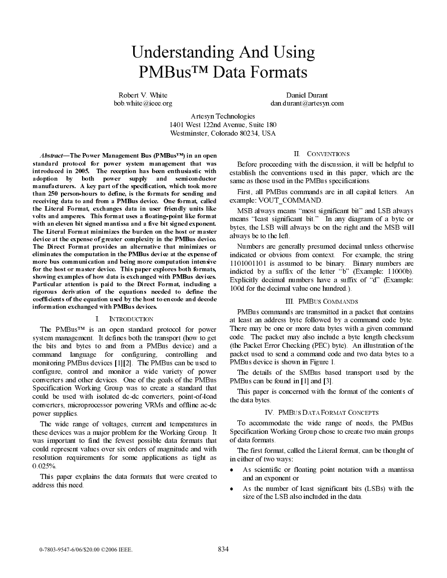
PMBus commands are transmitted in a packet that contains
at least an address byte followed by a command code byte.
There may be one or more data bytes with a given command
code. The packet may also include a byte length checksum
(the Packet Error Checking (PEC) byte). An illustration of the
packet used to send a command code and two data bytes to a
PMBus device is shown in Figure 1.
The details of the SMBus based transport used by the
PMBus can be found in [1] and [3].
This paper is concerned with the format of the contents of
the data bytes.
IV. PMBUS DATA FORMAT CONCEPTS
To accommodate the wide range of needs, the PMBus
Specification Working Group chose to create two main groups
of data formats.
The first format, called the Literal format, can be thought of
in either of two ways:
•
As scientific or floating point notation with a mantissa
This paper explains the data formats that were created to
and an exponent or
address this need.
•
As the number of least significant bits (LSBs) with the
size of the LSB also included in the data.
0-7803-9547-6/06/$20.00 ©2006 IEEE.
834
�
Address Byte
Command Code
S 7 6 5 4 3 2 1
W
r
A 7 6 5 4 3 2 1 0 A
Data Byte Low
Data Byte High
7 6 5 4 3 2 1 0 A 7 6 5 4 3 2 1 0 A
Optional PEC Byte
7 6 5 4 3 2 1 0
A
P
S
A
START Condition
From Host To Device
Acknowledge (ACK)
From Device To Host
W
r
P
Read/Write Bit
Set For Write (0)
STOP Condition
From Host To Device
Figure 1. PMBus Packet Construction
The Literal format allows the host to send values that are
independent of the PMBus device implementation, such as 3.3
to command an output voltage.
The other format is the Direct format. Direct format data
can be thought of as “raw” and in the native format of the
PMBus device. For example, the output voltage is not
commanded by sending a value such as 3.3 but a binary value
corresponding to a value between the minimum and maximum
rated output voltages.
The Literal and Direct formats are explained in depth
below.
The Working Group also created variations of each format
depending on whether or not the data was related to setting the
output voltage (or a related parameter such as the output
overvoltage fault limit) or not. The data formats for the output
voltage related commands were given the ability to command
a much smaller resolution. In addition, there is a mode for
output voltage related commands that sends the manufacturer
specified VID code for specified microprocessors.
This gives a total of five different ways that data can be
formatted for a PMBus device. The Working Group struggled
with this more than any other topic and decided this was the
minimum possible to cover all the desired applications and the
needs of those applications.
V. SETTING THE OUTPUT VOLTAGE
The output voltage of a PMBus device is set in two steps.
The first step uses the VOUT_MODE command to tell the
device the format of the output voltage related commands that
will be used to send commands to the device. This is usually
only done once or as needed. PMBus devices may also be
manufactured so that they accept output voltage and output
voltage related commands in one or a fixed subset of the
possible VOUT_MODE values.
The second command, VOUT_COMMAND, sends the
actual value. The data bytes for VOUT_COMMAND are a
sixteen bit unsigned binary integer. The output voltage
command instructs the device to set the voltage between the
positive and negative output terminals. Whether these
terminals are connected to ground to make a positive voltage
output, connected to make a negative voltage output, or left
flowing do not matter when commanding the output voltage.
More information on setting the output voltage and output
voltage related parameters can be found in Part II of the
PMBus Specification [2][4].
VI. GENERAL PURPOSE LITERAL FORMAT
The general purpose Literal format [2][4], as mentioned
above, can be thought of as a floating point number. The
mantissa, Y, is an eleven bit two’s complement binary integer.
The exponent, N, is a five bit two’s complement binary
integer. The value to be transmitted over the bus, X is
represented as:
X = Y · 2N
(1)
The combination of an eleven bit signed mantissa and a five
bit signed exponent allows for a wide range of values with
excellent resolution. The range of the values that can be
represented using the PMBus general purpose Literal format is
shown in Table I.
TABLE I. Range of values for Literal format data
Maximum Positive
Minimum Value
Maximum Negative
33.52 × 10⁶
(1023 × 215)
±15.26 × 10⁻⁶
(±1 × 2-16)
–33.55 × 10⁶
(–1024 × 215)
Another way of thinking of the Literal format is as a
combination of the number of LSBs (Y) and the size of the
LSB (2N). For example, if N = –10, 2N = 977 × 10–6, or about
1 mV/bit. The value of 3.3 could then be thought of as 3,379
LSBs, where each LSB = 2–10.
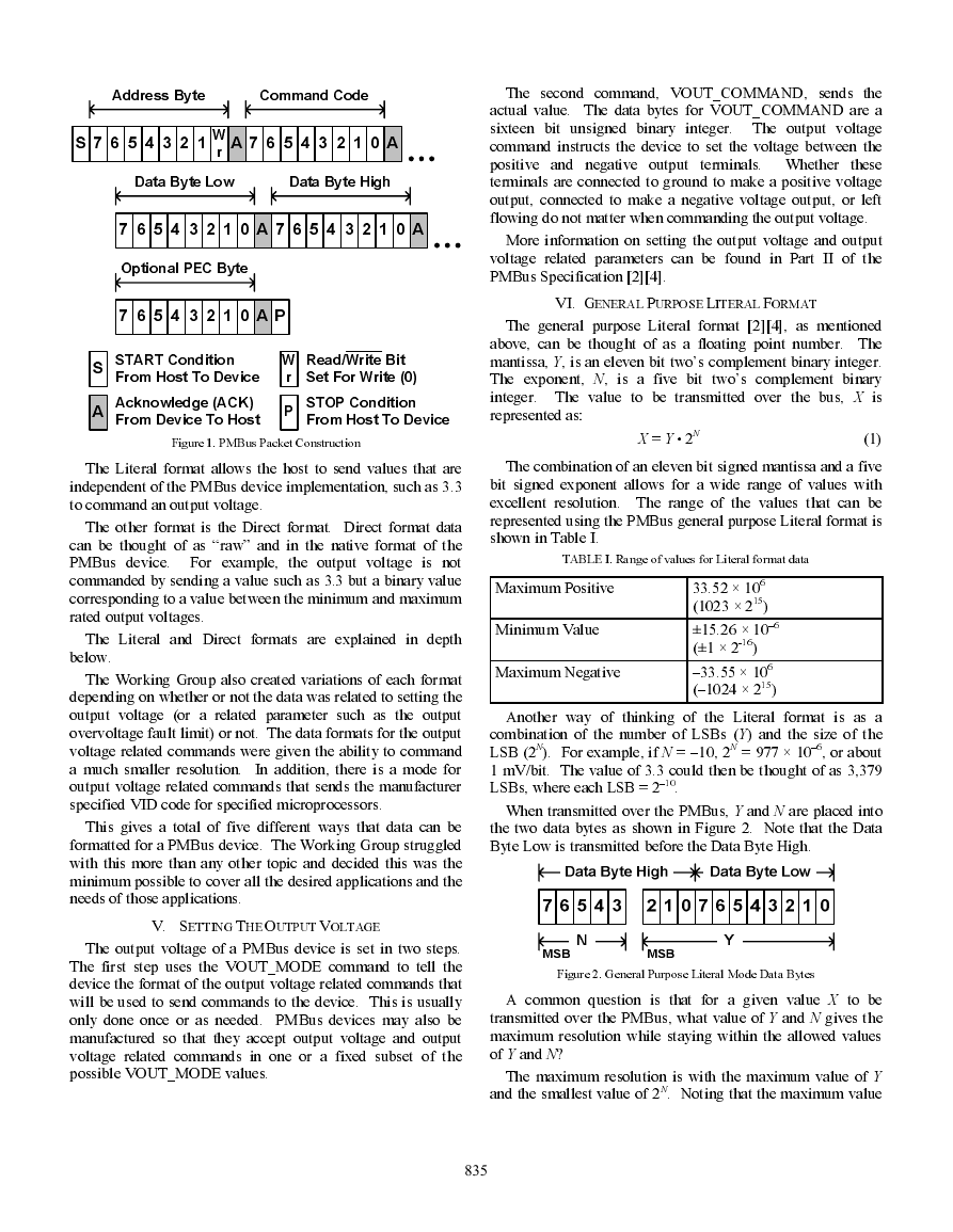
When transmitted over the PMBus, Y and N are placed into
the two data bytes as shown in Figure 2. Note that the Data
Byte Low is transmitted before the Data Byte High.
Figure 2. General Purpose Literal Mode Data Bytes
A common question is that for a given value X to be
transmitted over the PMBus, what value of Y and N gives the
maximum resolution while staying within the allowed values
of Y and N?
The maximum resolution is with the maximum value of Y
and the smallest value of 2N. Noting that the maximum value
835
�
of Y, YMAX =1023, it is possible to solve directly for N in terms
of X and YMAX as shown in (2) (where int(x) is the function that
returns the integer portion of x).
1. Separate the 16 bit value (1100001101001101) into Y
(01101001101) and N (11000).
2. Decode N to a decimal value (–8) and compute 2N
N
=
int
=
int
⎛
⎜
⎝
⎛
⎜
⎜
⎜
⎜
⎜
⎝
log
2
⎛
⎜
⎝
X
Y
MAX
⎞
⎟
⎠
⎞
⎟
⎠
ln
X
⎛
⎜
⎝
ln 2
Y
MAX
⎞
⎟
⎠
⎞
⎟
⎟
⎟
⎟
⎟
⎠
(2)
So for the example value of 3.3, then for maximum
resolution N = –8. Y is calculated as follows:
(1/256).
3. Decode Y to a decimal value (845).
4. Multiply Y (845) by 2N (1/256) to get 3.30078.
Note the introduction of the 780 µV error due to rounding
and quantization errors. Also, it is important that the
multiplication by 2N not be done in the binary domain by right
shifting the value of Y by 8 bits. If so, the result is simply 11b
or 3.0 in decimal!
VII. LINEAR FORMAT FOR OUTPUT VOLTAGE COMMANDS
Y
=
X −
2
i
N
=
3.3 2
i
− −
( 8)
=
844.8
⇒
845
However, for most of the embedded microprocessors used
for system maintenance and control, the calculation in (2) is
overly complex. To find Y and N for a given X in a simpler,
but somewhat longer calculation, start by dividing YMAX by X.
Assuming X = 3.3:
Then find the largest value of 2–N that is less than or equal
to that result:
max(2 ) 310.0
<
−
N
⇒
256
⇒ = − =
N
8 11000b
To find Y, multiply X by 2–N:
3.3 2
×
N−
8
3.3 2
×
=
=
3.3 256
×
=
844.8
⇒
845
⇒
01101001101b
(5)
(6)
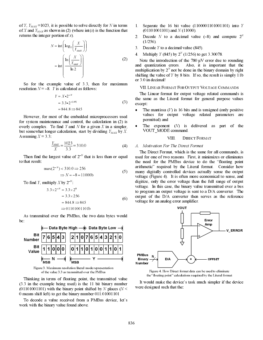
As transmitted over the PMBus, the two data bytes would
be:
Y
MAX
=
1023
X
3.3
=
310.0
(4)
A. Motivation For The Direct Format
The Linear format for output voltage related commands is
the same as the Literal format for general purpose values
except:
(3)
•
The mantissa (V) is 16 bits and is unsigned (only positive
related parameters are
for output voltage
values
permitted) and
•
The exponent
(N)
is delivered as part of
the
VOUT_MODE command.
VIII. DIRECT FORMAT
The Direct Format, which is the same for all commands, is
used for one of two reasons. First, it minimizes or eliminates
the need for the PMBus device to do the “floating point
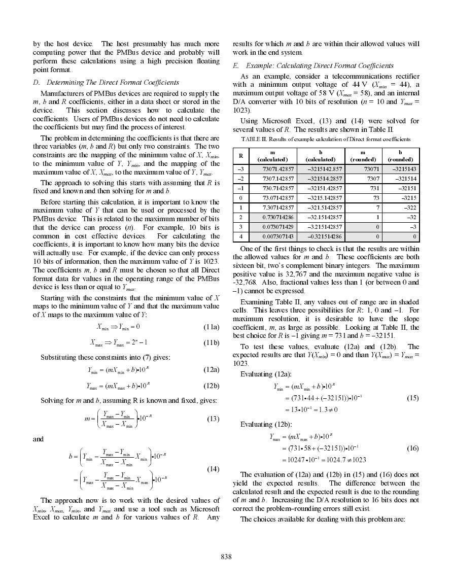
arithmetic” required by the Literal format. Consider how
many digitally controlled devices actually sense the output
voltage (Figure 4). It is often more economical to sense, and
digitize, only the error voltage than the full range of output
voltage. In this case, the binary value transmitted over a bus
to program an output voltage is sent to a D/A converter. The
output of the D/A converter then serves as the reference
voltage for an analog error amplifier.
VOUT
Error
Amp
V_ERROR
PMBus
Binary
Number
N
D/A
+
OFFSET
Figure 3. Maximum resolution literal mode representation
of the value 3.3 as transmitted over the PMBus
Thinking in terms of floating point, the transmitted value
(3.3 in the example being used) is the 11 bit binary number
(01101001101) with the binary point shifted by N places (N <
0 means shift left) to get the binary number 011.01001101
To decode a value received from a PMBus device, let’s
work with the binary value found above.
Figure 4. How Direct format data can be used to eliminate
the “floating point” calculations required by the Literal format
It would make the device’s task much simpler if the device
were designed such that the:
836
�
•
Minimum value transmitted over the bus (Ymin) set the
C. Using Direct Format Data
device output to its minimum rated output value, and the
•
Maximum value transmitted over the bus (Ymax) set the
device output to its maximum rated output value.
interest
is when
Another case of
the range being
commanded, such as a device’s output voltage, has a
substantial offset from zero. For example, rectifiers used in
telecommunications applications
typically have output
voltages that can be varied from about 44 Vdc to 58 Vdc.
Another requirement is that the output voltage be controlled
with a resolution in the range of 10-20 mV. And often, to
minimize cost, the D/A converters used for controlling the
output voltage have a resolution of only 10 bits.
However, to control the output voltage from 0 V to 58 V
with a resolution of even 20 mV requires at least 12 bits of
resolution (and 10 mV requires at least 13 bits). However, the
range from 44 V to 58 V can be controlled with a 10 bit D/A
with a resolution of 13.4 mV–which is good enough for most
applications.
This is made possible by the Direct format. In the Direct
format, the host sends a value of 0 over the bus to command
the output to 44 V and the maximum binary value the device
can use (such as 1023 for a device that has a 10 bit D/A) to
command the output to 58 V.
B.
Direct Format Equations
The Direct Mode actually uses an equation to define the
encoding of information sent to a PMBus device [2][4]. This
equation based encoding was inspired by the format used in
the Intelligent Peripheral Management Interface specification
[5].
The equation used to encode data being sent across the
PMBus is:
Where:
Y mX b+ i
=(
) 10 R
(7)
•
•
•
•
•
X
is the value to be encoded,
m, the slope coefficient, is a 16 bit two’s complement
integer,
b, the offset coefficient, is a 16 bit two’s complement
integer,
R, the scaling coefficient is an 8 bit two’s complement
integer, and
Y, the value transmitted over the bus, is a 16 bit two’s
complement integer.
To decode values received from a PMBus transmission, the
inverse of (7) is used:
X
=
1
m
R
−
(10
−i
Y b
)
(8)
The coefficients of the equation, m, b and R, are supplied by
the PMBus device manufacturer. They can be made available
from a data sheet or retrieved from the device itself with the
COEFFICIENTS command [2][4].
837
Before a host or master can send or retrieve Direct format
data from a PMBus device, it must have the m, b and R
coefficients used in (7) and (8). These values may either be
programmed into the host from values supplied in a data sheet
or they may be retrieved from the PMBus device using the
COEFFICIENTS command.
The details of using the
COEFFICIENTS command are given in [2] and [4].
Two examples will illustrate the use of Direct format data
for sending and receiving data from a PMBus device. In the
first example, the host is to send a command to a PMBus
device to set the output voltage to 3.30 V. In the second
example, the host will read back the actual output voltage
from the same device.
The cycle to send the command for the output voltage starts
with requesting the m, b and R coefficients for
the
VOUT_COMMAND command from the PMBus device.
Suppose the device returns the values m = 3615, b = –2892
and R = –1. The host uses (7) to calculate the value to be sent
over the bus (Y) using the desired output voltage of 3.3 for X.
Y mX b
+
=(
R
) 10
i
=
(3615 3.3 ( 2892)) 10
+ −
i
i
=
903.75
⇒
904
−
1
(9)
The decimal value of 904 is converted to a 16 bit unsigned
binary integer and sent over the bus to the PMBus device.
Now suppose that the host wants to know the actual output
voltage of the device whose output it just commanded to
3.3 V. The VOUT_COMMAND commands the nominal
output voltage setpoint of the PMBus device. However, there
are many factors that cause the actual output voltage to be
different from the VOUT_COMAND values. These factors
include tolerances within the PMBus, the effect of commands
that adjust the output voltage (such as VOUT_TRIM), and the
effect of current sharing circuits.
The PMBus specification provides the READ_VOUT
command that instructs the PMBus device to return the actual,
measured value of the output voltage. When using Direct
format data, the host starts the process of requesting the actual
output voltage by requesting from the PMBus device the m, b
and R coefficients for the READ_VOUT command. Suppose
the device returns the values m = 10240, b = 0 and R = –1.
The host then sends the PMBus device a READ_VOUT
command. Suppose the device returned the value 3364d. The
host then uses (8) to calculate the output voltage:
X
=
1
m
−
R
(10
Y b
−
i
)
1
=
=
10240
3.285
− −
( 1)
(10
i
3364 0)
−
(10)
From this calculation, the device’s actual, measured output
voltage is reported as 3.285 V.
It is important to note that the calculations (9) and (10) are
not done in the PMBus device. These calculations are made
�
by the host device. The host presumably has much more
computing power that the PMBus device and probably will
perform these calculations using a high precision floating
point format.
D. Determining The Direct Format Coefficients
Manufacturers of PMBus devices are required to supply the
m, b and R coefficients, either in a data sheet or stored in the
device.
the
coefficients. Users of PMBus devices do not need to calculate
the coefficients but may find the process of interest.
This section discusses how
to calculate
The problem in determining the coefficients is that there are
three variables (m, b and R) but only two constraints. The two
constraints are the mapping of the minimum value of X, Xmin,
to the minimum value of Y, Ymin, and the mapping of the
maximum value of X, Xmax, to the maximum value of Y, Ymax.
The approach to solving this starts with assuming that R is
fixed and known and then solving for m and b.
Before starting this calculation, it is important to know the
maximum value of Y that can be used or processed by the
PMBus device. This is related to the maximum number of bits
that the device can process (n). For example, 10 bits is
common in cost effective devices. For calculating the
coefficients, it is important to know how many bits the device
will actually use. For example, if the device can only process
10 bits of information, then the maximum value of Y is 1023.
The coefficients m, b and R must be chosen so that all Direct
format data for values in the operating range of the PMBus
device is less than or equal to Ymax.
Starting with the constraints that the minimum value of X
maps to the minimum value of Y and that the maximum value
of X maps to the maximum value of Y:
X
min
Y⇒ =
0
min
X
max
Y⇒ =
max
2
1n
−
Substituting these constraints into (7) gives:
Y
min
=
mX
(
min
+ i
) 10R
b
Y
max
=
mX
(
max
+ i
) 10 R
b
(11a)
(11b)
(12a)
(12b)
Solving for m and b, assuming R is known and fixed, gives:
m
⎛
= ⎜
⎝
Y
max
X
max
−
−
Y
min
X
min
and
−
10 R
i
⎞
⎟
⎠
b
=
=
⎛
⎜
⎝
⎛
⎜
⎝
Y
min
−
Y
max
−
Y
max
X
max
Y
max
X
max
−
−
−
−
Y
min
X
min
Y
min
X
min
X
min
X
max
⎞
⎟
⎠
⎞
⎟
⎠
(13)
(14)
−
R
10
i
−
R
10
i
The approach now is to work with the desired values of
Xmin, Xmax
, Ymin, and Ymax and use a tool such as Microsoft
Excel to calculate m and b for various values of R. Any
838
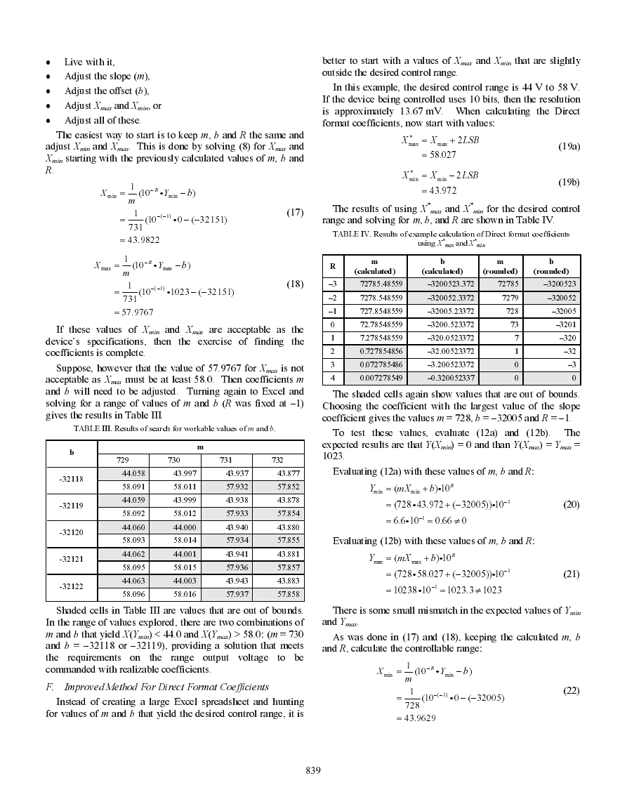
results for which m and b are within their allowed values will
work in the end system.
E. Example: Calculating Direct Format Coefficients
As an example, consider a telecommunications rectifier
with a minimum output voltage of 44 V (Xmin = 44), a
maximum output voltage of 58 V (Xmax = 58), and an internal
D/A converter with 10 bits of resolution (n = 10 and Ymax =
1023).
Using Microsoft Excel, (13) and (14) were solved for
several values of R. The results are shown in Table II.
TABLE II. Results of example calculation of Direct format coefficients
R
–3
–2
–1
0
1
2
3
4
m
b
m
b
(calculated)
(calculated)
(rounded)
(rounded)
73071.42857
–3215142.857
73071
–3215143
7307.142857
–321514.2857
7307
–321514
730.7142857
–32151.42857
73.07142857
–3215.142857
7.307142857
–321.5142857
0.730714286
–32.15142857
0.073071429
–3.215142857
0.007307143
–0.321514286
731
73
7
1
0
0
–32151
–3215
–322
–32
–3
0
One of the first things to check is that the results are within
the allowed values for m and b. These coefficients are both
sixteen bit, two’s complement binary integers. The maximum
positive value is 32,767 and the maximum negative value is
-32,768. Also, fractional values less than 1 (or between 0 and
–1) cannot be expressed.
Examining Table II, any values out of range are in shaded
cells. This leaves three possibilities for R: 1, 0 and –1. For
maximum resolution, it is desirable to have the slope
coefficient, m, as large as possible. Looking at Table II, the
best choice for R is –1 giving m = 731 and b = –32151.
To test these values, evaluate (12a) and (12b). The
expected results are that Y(Xmin) = 0 and than Y(Xmax) = Ymax =
1023.
Evaluating (12a):
Y
min
=
mX
(
min
+
b
) 10
i
R
=
=
(731 44 ( 32151)) 10
+ −
i
i
1
−
13 10
i
=
1.3 0
≠
1
−
(15)
Evaluating (12b):
Y
max
=
mX
(
max
+
b
) 10
i
R
=
(731 58 ( 32151)) 10
+ −
i
i
1
−
(16)
=
10247 10
i
−
1
=
1024.7 1023
≠
The evaluation of (12a) and (12b) in (15) and (16) does not
yield the expected results. The difference between the
calculated result and the expected result is due to the rounding
of m and b. Increasing the D/A resolution to 16 bits does not
correct the problem–rounding errors still exist.
The choices available for dealing with this problem are:
�
•
Live with it,
•
Adjust the slope (m),
•
Adjust the offset (b),
•
Adjust Xmax and Xmin, or
•
Adjust all of these.
The easiest way to start is to keep m, b and R the same and
adjust Xmin and Xmax. This is done by solving (8) for Xmax and
Xmin starting with the previously calculated values of m, b and
R.
X
=
min
1
m
−
R
i
(10
Y
min
−
b
)
1
− −
( 1)
(10
=
=
731
43.9822
i
0 ( 32151)
− −
better to start with a values of Xmax and Xmin that are slightly
outside the desired control range.
In this example, the desired control range is 44 V to 58 V.
If the device being controlled uses 10 bits, then the resolution
is approximately 13.67 mV. When calculating the Direct
format coefficients, now start with values:
X
*
max
=
X
max
+
2
LSB
=
58.027
X
*
min
=
X
min
−
2
LSB
=
43.972
(19a)
(19b)
(17)
The results of using X
*
*
max and X
min for the desired control
range and solving for m, b, and R
are shown in Table IV.
TABLE IV. Results of example calculation of Direct format coefficients
*
*
using X
min
max and X
X
=
max
1
m
−
R
i
(10
Y
max
−
b
)
1
− −
( 1)
(10
=
=
731
57.9767
i
1023 ( 32151)
− −
(18)
If these values of Xmin and Xmax are acceptable as the
device’s specifications, then the exercise of finding the
coefficients is complete.
Suppose, however that the value of 57.9767 for Xmax is not
acceptable as Xmax must be at least 58.0. Then coefficients m
and b will need to be adjusted. Turning again to Excel and
solving for a range of values of m and b (R was fixed at –1)
gives the results in Table III.
TABLE III. Results of search for workable values of m and b.
729
730
731
732
m
R
–3
–2
–1
0
1
2
3
4
m
b
m
b
(calculated)
(calculated)
(rounded)
(rounded)
72785.48559
–3200523.372
72785
–3200523
7278.548559
–320052.3372
7279
–320052
727.8548559
–32005.23372
72.78548559
–3200.523372
7.278548559
–320.0523372
0.727854856
–32.00523372
0.072785486
–3.200523372
0.007278549
–0.320052337
728
73
7
1
0
0
–32005
–3201
–320
–32
–3
0
The shaded cells again show values that are out of bounds.
Choosing the coefficient with the largest value of the slope
coefficient gives the values m = 728, b = –32005 and R = –1.
To test these values, evaluate (12a) and (12b). The
expected results are that Y(Xmin) = 0 and than Y(Xmax) = Ymax =
1023.
44.058
43.997
43.937
43.877
Evaluating (12a) with these values of m, b and R:
58.091
58.011
57.932
57.852
44.059
43.999
43.938
43.878
58.092
58.012
57.933
57.854
44.060
44.000
43.940
43.880
Y
min
=
mX
(
min
+
b
) 10
i
R
=
(728 43.972 ( 32005)) 10
+ −
i
i
=
6.6 10
i
1
−
=
0.66 0
≠
1
−
58.093
58.014
57.934
57.855
Evaluating (12b) with these values of m, b and R:
44.062
44.001
43.941
43.881
58.095
58.015
57.936
57.857
44.063
44.003
43.943
43.883
58.096
58.016
57.937
57.858
Y
max
=
mX
(
max
+
b
) 10
i
R
=
(728 58.027 ( 32005)) 10
+ −
i
i
=
10238 10
i
1
−
=
1023.3 1023
≠
−
1
(20)
(21)
b
-32118
-32119
-32120
-32121
-32122
Shaded cells in Table III are values that are out of bounds.
In the range of values explored, there are two combinations of
m and b that yield X(Ymin) < 44.0 and X(Ymax) > 58.0: (m = 730
and b = –32118 or –32119), providing a solution that meets
the requirements on
to be
commanded with realizable coefficients.
the range output voltage
F. Improved Method For Direct Format Coefficients
Instead of creating a large Excel spreadsheet and hunting
for values of m and b that yield the desired control range, it is
839
There is some small mismatch in the expected values of Ymin
and Ymax.
As was done in (17) and (18), keeping the calculated m, b
and R, calculate the controllable range:
X
=
min
1
m
−
R
i
(10
Y
min
−
b
)
1
− −
( 1)
(10
=
=
728
43.9629
i
0 ( 32005)
− −
(22)
�
X
=
max
1
m
−
R
i
(10
Y
max
−
b
)
1
− −
( 1)
(10
=
=
728
58.0151
i
1023 ( 32005)
− −
(23)
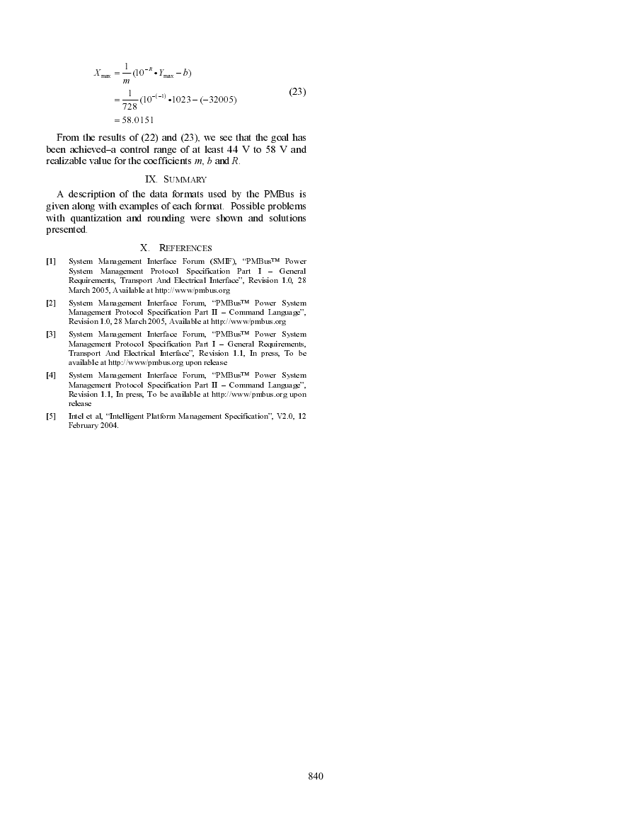
From the results of (22) and (23), we see that the goal has
been achieved–a control range of at least 44 V to 58 V and
realizable value for the coefficients m, b and R.
IX. SUMMARY
A description of the data formats used by the PMBus is
given along with examples of each format. Possible problems
with quantization and rounding were shown and solutions
presented.
X. REFERENCES
[1]
[2]
[3]
[4]
System Management Interface Forum (SMIF), “PMBus™ Power
System Management Protocol Specification Part I – General
Requirements, Transport And Electrical Interface”, Revision 1.0, 28
March 2005, Available at http://www/pmbus.org
System Management Interface Forum, “PMBus™ Power System
Management Protocol Specification Part II – Command Language”,
Revision 1.0, 28 March 2005, Available at http://www/pmbus.org
System Management Interface Forum, “PMBus™ Power System
Management Protocol Specification Part I – General Requirements,
Transport And Electrical Interface”, Revision 1.1, In press, To be
available at http://www/pmbus.org upon release
System Management Interface Forum, “PMBus™ Power System
Management Protocol Specification Part II – Command Language”,
Revision 1.1, In press, To be available at http://www/pmbus.org upon
release
[5]
Intel et al, “Intelligent Platform Management Specification”, V2.0, 12
February 2004.
840
�



 2023年江西萍乡中考道德与法治真题及答案.doc
 2012年重庆南川中考生物真题及答案.doc
 2013年江西师范大学地理学综合及文艺理论基础考研真题.doc
 2020年四川甘孜小升初语文真题及答案I卷.doc
 2020年注册岩土工程师专业基础考试真题及答案.doc
 2023-2024学年福建省厦门市九年级上学期数学月考试题及答案.doc
 2021-2022学年辽宁省沈阳市大东区九年级上学期语文期末试题及答案.doc
 2022-2023学年北京东城区初三第一学期物理期末试卷及答案.doc
 2018上半年江西教师资格初中地理学科知识与教学能力真题及答案.doc
 2012年河北国家公务员申论考试真题及答案-省级.doc
 2020-2021学年江苏省扬州市江都区邵樊片九年级上学期数学第一次质量检测试题及答案.doc
 2022下半年黑龙江教师资格证中学综合素质真题及答案.doc