t
n
e
m
u
c
o
d
l
i
a
n
g
i
r
o
e
h
t
l
o
r
t
n
o
c
o
t
.
t
p
e
D
e
t
a
D
THERMAL PRINTER
FTP-628MCL101#50
PRODUCT SPECIFICATION
(Corresponds to RoHS)
e
m
a
N
FTP-628MCL101#50 SPECIFICATION
02 07.03.05 M.Tsuchiya
Rev.
Design
Date
06.01.14 Y,Takabatake
Design
Inspection
Inspect.
For Vdd=3v (p17,22,24,36change) Y.Mori
i
g
n
w
a
r
D
.
o
N
Submit to
Changes made
Approv.
Y.Mori
FUJITSU COMPONENT LIMITED
1
e
g
a
P
36
�
t
n
e
m
u
c
o
d
l
i
a
n
g
i
r
o
e
h
t
l
o
r
t
n
o
c
o
t
.
t
p
e
D
e
t
a
D
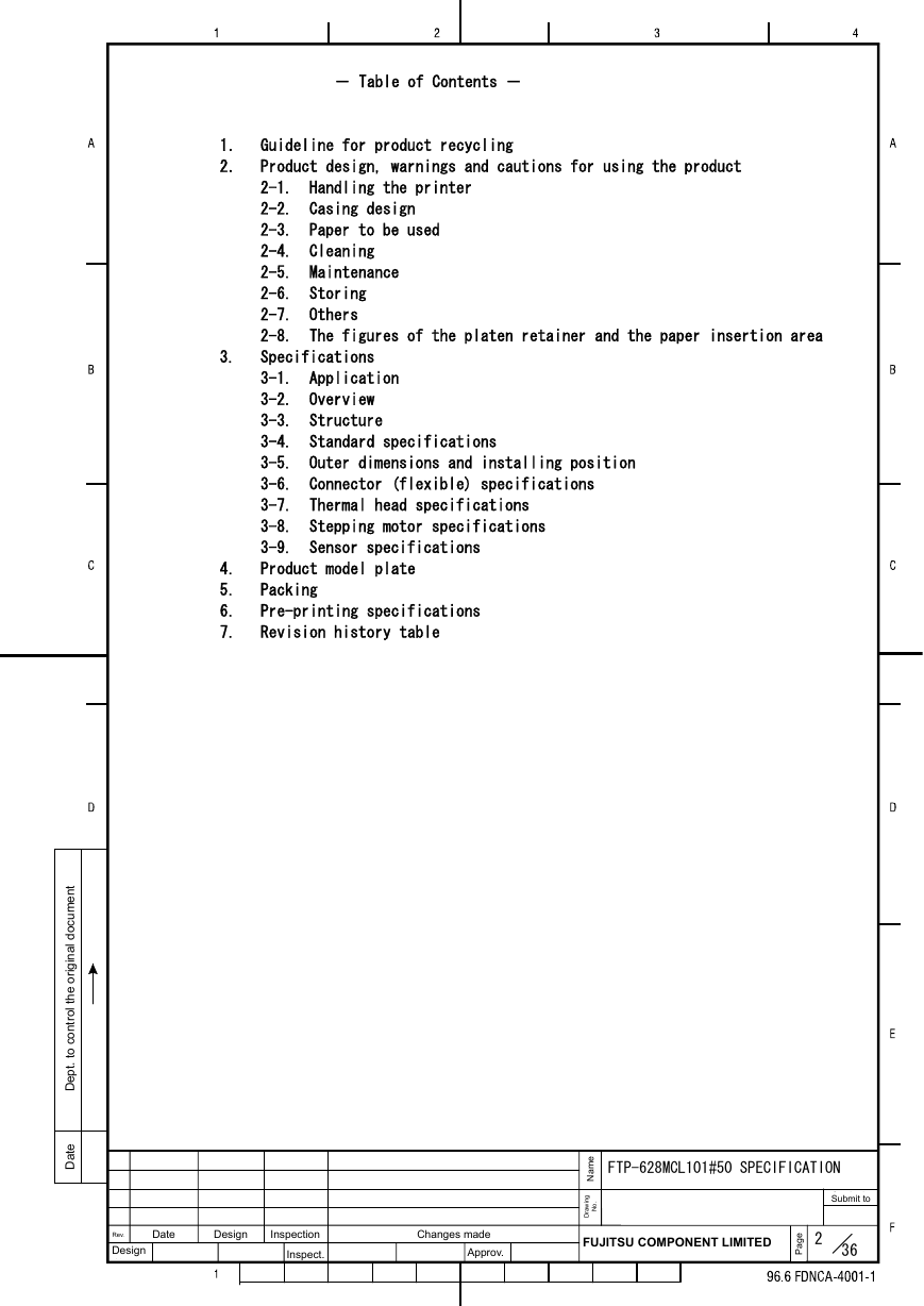
- Table of Contents -
1. Guideline for product recycling
2. Product design, warnings and cautions for using the product
2-1. Handling the printer
2-2. Casing design
2-3. Paper to be used
2-4. Cleaning
2-5. Maintenance
2-6. Storing
2-7. Others
2-8. The figures of the platen retainer and the paper insertion area
3. Specifications
3-1. Application
3-2. Overview
3-3. Structure
3-4. Standard specifications
3-5. Outer dimensions and installing position
3-6. Connector (flexible) specifications
3-7. Thermal head specifications
3-8. Stepping motor specifications
3-9. Sensor specifications
4. Product model plate
5. Packing
6. Pre-printing specifications
7. Revision history table
e
m
a
N
FTP-628MCL101#50 SPECIFICATION
Date
Design
Rev.
Design
Inspection
Inspect.
Changes made
Approv.
FUJITSU COMPONENT LIMITED
2
e
g
a
P
36
i
g
n
w
a
r
D
.
o
N
Submit to
�
t
n
e
m
u
c
o
d
l
i
a
n
g
i
r
o
e
h
t
l
o
r
t
n
o
c
o
t
.
t
p
e
D
e
t
a
D
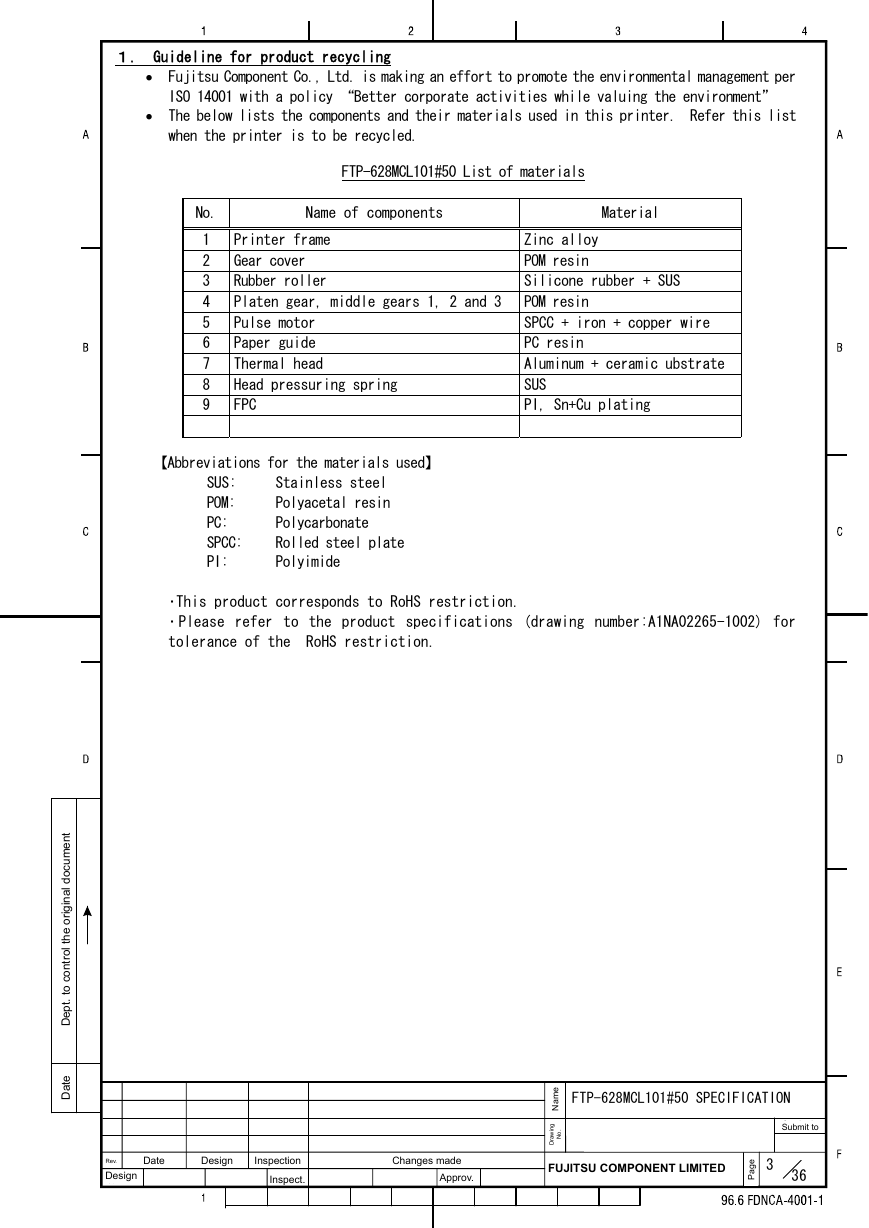
1. Guideline for product recycling
• Fujitsu Component Co., Ltd. is making an effort to promote the environmental management per
ISO 14001 with a policy “Better corporate activities while valuing the environment”
• The below lists the components and their materials used in this printer. Refer this list
when the printer is to be recycled.
FTP-628MCL101#50 List of materials
No.
Name of components
Material
1
2
3
4
5
6
7
8
9
Printer frame
Gear cover
Rubber roller
Platen gear, middle gears 1, 2 and 3
Pulse motor
Paper guide
Thermal head
Head pressuring spring
FPC
Zinc alloy
POM resin
Silicone rubber + SUS
POM resin
SPCC + iron + copper wire
PC resin
Aluminum + ceramic ubstrate
SUS
PI, Sn+Cu plating
【Abbreviations for the materials used】
SUS:
POM:
PC:
SPCC:
PI:
Stainless steel
Polyacetal resin
Polycarbonate
Rolled steel plate
Polyimide
・This product corresponds to RoHS restriction.
・ Please refer to the product specifications (drawing number:A1NA02265-1002) for
tolerance of the RoHS restriction.
e
m
a
N
FTP-628MCL101#50 SPECIFICATION
Date
Design
Rev.
Design
Inspection
Inspect.
Changes made
Approv.
FUJITSU COMPONENT LIMITED
3
e
g
a
P
36
i
g
n
w
a
r
D
.
o
N
Submit to
�
t
n
e
m
u
c
o
d
l
i
a
n
g
i
r
o
e
h
t
l
o
r
t
n
o
c
o
t
.
t
p
e
D
e
t
a
D
2.Product design, warnings and cautions for using the product
(5)
(4)
(3)
(2)
2-1.Handling the printer
(1) When handling this printer, be sure to take any preventive measure against static
electricity such as Disposable Wrist Strap in order to prevent damages of inner parts
of the printer caused by the static electricity.
When attaching the platen part to the platen retainer, pay attention not to flaw or
damage or smear the rubber part of the platen, the platen gear, and the bearing part
(particularly, do not attach any oil or grease and foreign material on the rubber
part).
Never attempt to touch the thermal head surface with bear hands. Attaching any oil
or grease such as oils from palms on the heating element part may be shorten the
lifetime of the thermal head. In case that any oil and grease or foreign materials
are attached on it, perform the cleaning immediately. (Section 2-4 describes the
cleaning.) In addition, pay attention not to hit it with something hard such as a
driver.
When attaching the platen to the platen retainer of the casing, make sure that the
attaching orientation of the right and left is correct.
The thermal head and FPC are shipped as they are connected. When installing the
printer, do not pull or apply any extra force in order to avoid the connected part
of the thermal head and FPC from being disconnected or deviated. Using the printer
with the part is deviated may destroy the head. If it is deviated or disconnected,
contact us.
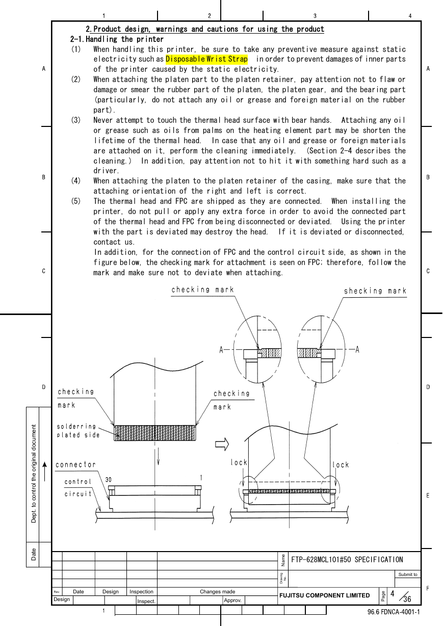
In addition, for the connection of FPC and the control circuit side, as shown in the
figure below, the checking mark for attachment is seen on FPC; therefore, follow the
mark and make sure not to deviate when attaching.
e
m
a
N
FTP-628MCL101#50 SPECIFICATION
Date
Design
Rev.
Design
Inspection
Inspect.
Changes made
Approv.
FUJITSU COMPONENT LIMITED
4
e
g
a
P
36
i
g
n
w
a
r
D
.
o
N
Submit to
�
t
n
e
m
u
c
o
d
l
i
a
n
g
i
r
o
e
h
t
l
o
r
t
n
o
c
o
t
.
t
p
e
D
e
t
a
D
(6)
(7)
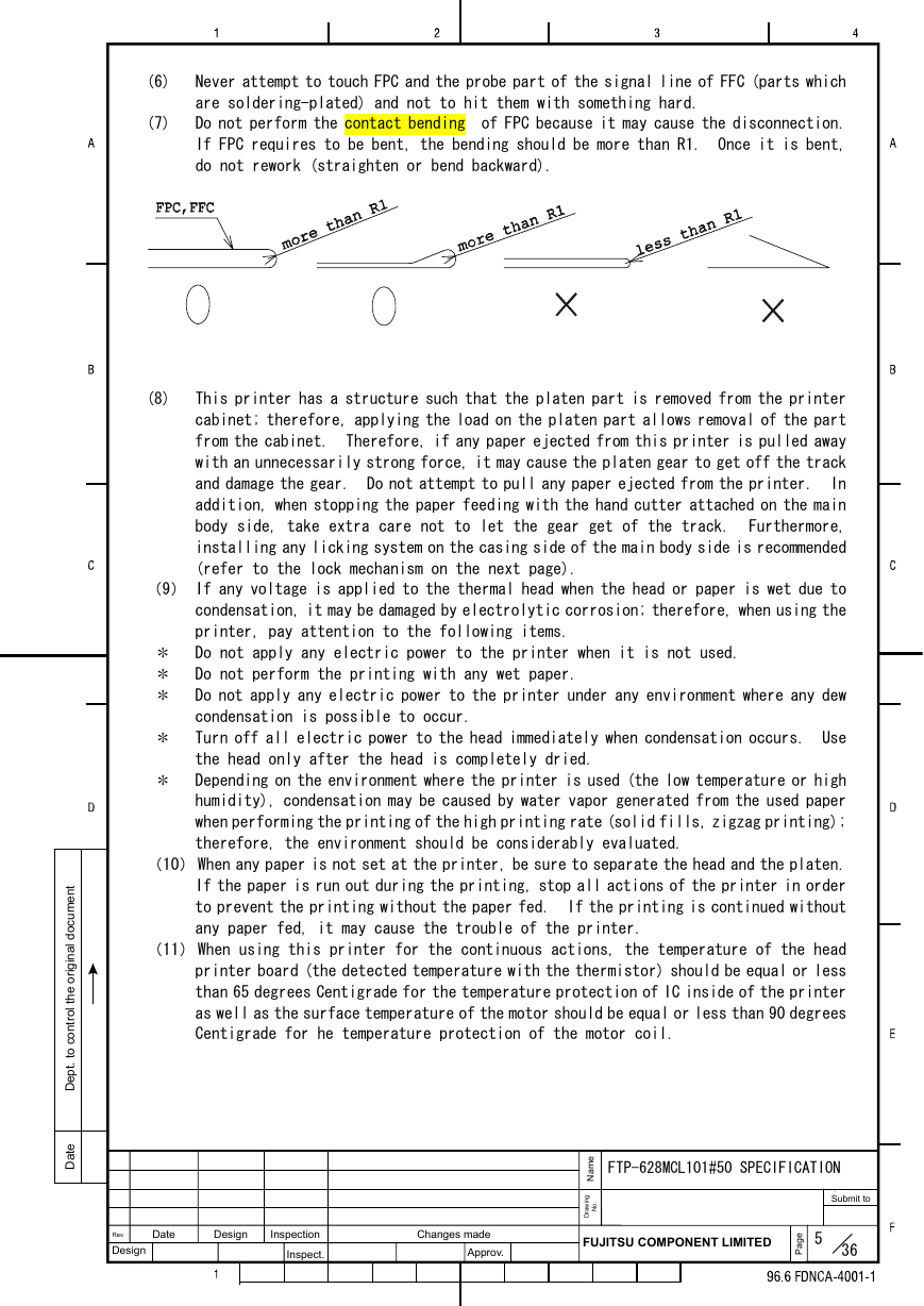
Never attempt to touch FPC and the probe part of the signal line of FFC (parts which
are soldering-plated) and not to hit them with something hard.
Do not perform the contact bending of FPC because it may cause the disconnection.
If FPC requires to be bent, the bending should be more than R1. Once it is bent,
do not rework (straighten or bend backward).
(8)
This printer has a structure such that the platen part is removed from the printer
cabinet; therefore, applying the load on the platen part allows removal of the part
from the cabinet. Therefore, if any paper ejected from this printer is pulled away
with an unnecessarily strong force, it may cause the platen gear to get off the track
and damage the gear. Do not attempt to pull any paper ejected from the printer. In
addition, when stopping the paper feeding with the hand cutter attached on the main
body side, take extra care not to let the gear get of the track. Furthermore,
installing any licking system on the casing side of the main body side is recommended
(refer to the lock mechanism on the next page).
*
*
*
(9) If any voltage is applied to the thermal head when the head or paper is wet due to
condensation, it may be damaged by electrolytic corrosion; therefore, when using the
printer, pay attention to the following items.
Do not apply any electric power to the printer when it is not used.
Do not perform the printing with any wet paper.
Do not apply any electric power to the printer under any environment where any dew
condensation is possible to occur.
Turn off all electric power to the head immediately when condensation occurs. Use
the head only after the head is completely dried.
Depending on the environment where the printer is used (the low temperature or high
humidity), condensation may be caused by water vapor generated from the used paper
when performing the printing of the high printing rate (solid fills, zigzag printing);
therefore, the environment should be considerably evaluated.
*
*
(10) When any paper is not set at the printer, be sure to separate the head and the platen.
If the paper is run out during the printing, stop all actions of the printer in order
to prevent the printing without the paper fed. If the printing is continued without
any paper fed, it may cause the trouble of the printer.
(11) When using this printer for the continuous actions, the temperature of the head
printer board (the detected temperature with the thermistor) should be equal or less
than 65 degrees Centigrade for the temperature protection of IC inside of the printer
as well as the surface temperature of the motor should be equal or less than 90 degrees
Centigrade for he temperature protection of the motor coil.
e
m
a
N
FTP-628MCL101#50 SPECIFICATION
Date
Design
Rev.
Design
Inspection
Inspect.
Changes made
Approv.
FUJITSU COMPONENT LIMITED
5
e
g
a
P
36
i
g
n
w
a
r
D
.
o
N
Submit to
�
t
n
e
m
u
c
o
d
l
i
a
n
g
i
r
o
e
h
t
l
o
r
t
n
o
c
o
t
.
t
p
e
D
e
t
a
D
(12) Never attempt to any back feeding action of the paper.
(13) This printer is using the infrared photo-sensor for paper-end detection and mark
detection. For this reason, if it is used in a strong light like sunlight, a sensor
may incorrect-operate. When you use it in such an environment, please evaluate enough.
And if needed, please cope with it to prevent from such light.
(14) When a printer is used near a mobile terminal or a radio, there is a possibility that
the obstacle occurs by the electromagnetic radiation noise. When using a printer in
such an environment, please evaluate enough. And if needed, please cope with it with
a shield or grounding reinforcement etc.
2-2.Casing design
□Platen retainer
(1) Refer to Attached Paper, Section 2-8 "The figures of the platen retainer and the paper
insertion area" for attachment of the platen part. If it is used with any different
size from the recommended ones, it may cause uneven printing, unfavorable removal
of the platen, and troubles such as damages due to the lack of the strength; therefore,
be sure to conform with the recommendation. The recommended dimension of the
retainer is in a range where the angle is 11°±0.5° and the size of the X-direction
is 50-200 mm.
(2) Cover the platen gear part so that it is not exposed. The platen has some play against
the retainer part; therefore, the gap between the platen gear and the cover should
have sufficiently play.
(3) Materials of the platen retainer should have high strength and high impact-resistance
as the ones for the platen retainer (equivalent to PC or PC+ABS).
(4) Avoid removing the platen from the platen retainer as much as possible after having
attached it to the platen retainer.
(5) Please install the cover on the case side so that neither garbage nor the foreign
body may enter the PLATEN open and close detection switch of the printer in the gear
box as much as possible. When garbage and the foreign body, etc. enter, it causes
the breakdown.
e
m
a
N
FTP-628MCL101#50 SPECIFICATION
Date
Design
Rev.
Design
Inspection
Inspect.
Changes made
Approv.
FUJITSU COMPONENT LIMITED
6
e
g
a
P
36
i
g
n
w
a
r
D
.
o
N
Submit to
�
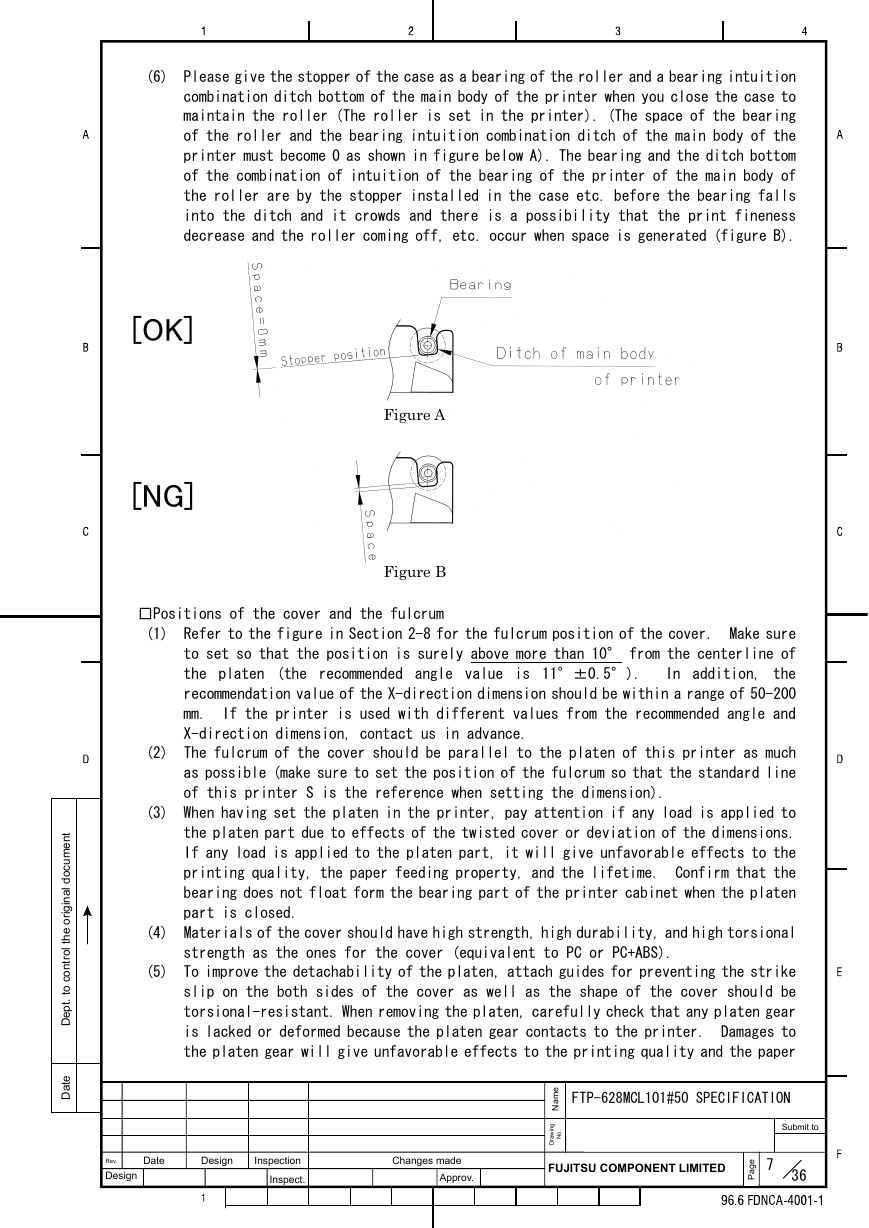
(6) Please give the stopper of the case as a bearing of the roller and a bearing intuition
combination ditch bottom of the main body of the printer when you close the case to
maintain the roller (The roller is set in the printer). (The space of the bearing
of the roller and the bearing intuition combination ditch of the main body of the
printer must become 0 as shown in figure below A). The bearing and the ditch bottom
of the combination of intuition of the bearing of the printer of the main body of
the roller are by the stopper installed in the case etc. before the bearing falls
into the ditch and it crowds and there is a possibility that the print fineness
decrease and the roller coming off, etc. occur when space is generated (figure B).
[OK]
[NG]
Figure A
Figure B
□Positions of the cover and the fulcrum
(1) Refer to the figure in Section 2-8 for the fulcrum position of the cover. Make sure
to set so that the position is surely above more than 10° from the centerline of
the platen (the recommended angle value is 11°±0.5°). In addition, the
recommendation value of the X-direction dimension should be within a range of 50-200
mm. If the printer is used with different values from the recommended angle and
X-direction dimension, contact us in advance.
(2) The fulcrum of the cover should be parallel to the platen of this printer as much
as possible (make sure to set the position of the fulcrum so that the standard line
of this printer S is the reference when setting the dimension).
(3) When having set the platen in the printer, pay attention if any load is applied to
the platen part due to effects of the twisted cover or deviation of the dimensions.
If any load is applied to the platen part, it will give unfavorable effects to the
printing quality, the paper feeding property, and the lifetime. Confirm that the
bearing does not float form the bearing part of the printer cabinet when the platen
part is closed.
(4) Materials of the cover should have high strength, high durability, and high torsional
strength as the ones for the cover (equivalent to PC or PC+ABS).
(5) To improve the detachability of the platen, attach guides for preventing the strike
slip on the both sides of the cover as well as the shape of the cover should be
torsional-resistant. When removing the platen, carefully check that any platen gear
is lacked or deformed because the platen gear contacts to the printer. Damages to
the platen gear will give unfavorable effects to the printing quality and the paper
e
m
a
N
FTP-628MCL101#50 SPECIFICATION
t
n
e
m
u
c
o
d
l
i
a
n
g
i
r
o
e
h
t
l
o
r
t
n
o
c
o
t
.
t
p
e
D
e
t
a
D
Date
Design
Rev.
Design
Inspection
Inspect.
Changes made
Approv.
FUJITSU COMPONENT LIMITED
7
e
g
a
P
36
i
g
n
w
a
r
D
.
o
N
Submit to
�
t
n
e
m
u
c
o
d
l
i
a
n
g
i
r
o
e
h
t
l
o
r
t
n
o
c
o
t
.
t
p
e
D
e
t
a
D
feeding property.
(6) The paper feeding motor (a pulse motor) of the printer and the thermal head may have
the hot temperature, depending on the running time. When designing the casing,
consider the heat radiation property. Be sure to design the casing so that no one
is allowed to directly touch with bear hands such as adopting a cover structure, etc.
□Lock mechanism of the casing
(1) The platen retainer part of this printer provides an easy retaining (locking)
mechanism (the printer as a single unit can perform the printing action), which
comprises of the pressure of the head and the shape of the bearing part of the sideboard.
However, if the following items are considered, the lock mechanism is recommended
to mount on the casing side.
(2) When using with a portable terminal, the casing may be opened and the rolled paper
inside may jump out when it is dropped or moved (particularly, while it is being
carried).
(3) Depending on the attaching orientation of the printer, loads of the cover or the
rolled paper may work to directions to which the platen is removed. Due to that,
the platen gear may get off the track or the platen may be detached during the printing.
(4) When cutting the paper ejected from the printer with a manual cutter or depending
on the pulling direction of the paper, the platen gear may get off the track or the
platen may be detached (when locking, minimize the play of the platen as much as
possible).
□Installing the printer
(1) When installing the printer, fix the edge part with a hook at one place and fix the
rear part with screws of M2 at two places. Flatness of the installing surface of
the printer should be within equal or less than 0.1mm. It is recommended that the
printer is connected to the main body FG with screws of M2 at two places (refer to
the figure of the installation dimension). Pay attention not to apply any extra force
to the printer main body and FPC since any of such force will give unfavorable effects
to the printing quality, paper traveling property (meandering, running short of the
paper, and the paper jam), and life time.
(2) When installing the printer, install it so that the printer and the rolled paper
should be parallel as much as possible. When designing the casing, it should be
designed so that the printer and the holder part of the roller paper are located at
the place shown in the Fig (6) in Section 2-8. The roller paper should be ejected
smoothly so that the paper does not hit anything such as the cover. If the above
is not conformed, troubles such as meandering of the printing paper, the running short
of the paper, and the paper jam may occur.
(3) The paper detection sensor is provided on the main body side of the printer; therefore,
be sure to design the paper holder so that the printing paper surely contact to the
sensor (refer to Section 2-8). If the printing paper floats on the sensor equal or
greater than 0.7mm, the sensor may determines the paper is not fed; therefore, attach
paper holding guides on the casing side for preventing the paper from floating. In
addition, when the roller paper is close to the end and the last part of it comes
to the paper opening paper of the printer, the paper jam may occur at the opening.
This paper holding guide works as the preventive measure of this paper jam; therefore,
adding this guide to the casing is recommended.
(4) When plugging in and out FPC to the connector of the control side, be sure that all
power is turned off before doing that.
e
m
a
N
FTP-628MCL101#50 SPECIFICATION
Date
Design
Rev.
Design
Inspection
Inspect.
Changes made
Approv.
FUJITSU COMPONENT LIMITED
8
e
g
a
P
36
i
g
n
w
a
r
D
.
o
N
Submit to
�


 2023年江西萍乡中考道德与法治真题及答案.doc
 2012年重庆南川中考生物真题及答案.doc
 2013年江西师范大学地理学综合及文艺理论基础考研真题.doc
 2020年四川甘孜小升初语文真题及答案I卷.doc
 2020年注册岩土工程师专业基础考试真题及答案.doc
 2023-2024学年福建省厦门市九年级上学期数学月考试题及答案.doc
 2021-2022学年辽宁省沈阳市大东区九年级上学期语文期末试题及答案.doc
 2022-2023学年北京东城区初三第一学期物理期末试卷及答案.doc
 2018上半年江西教师资格初中地理学科知识与教学能力真题及答案.doc
 2012年河北国家公务员申论考试真题及答案-省级.doc
 2020-2021学年江苏省扬州市江都区邵樊片九年级上学期数学第一次质量检测试题及答案.doc
 2022下半年黑龙江教师资格证中学综合素质真题及答案.doc