EDA 期末作业
班级:020914
(一)选题目的
学习使用 QuartusII 9.0,巩固已掌握的 EDA 知识,增强自己的动手实践能力。
�
(二)设计目标
实现多功能数字钟的设计,主要有以下功能:
①计时,并且可以 24 小时制和 12 小时制转换。
②闹钟
③整点报时
④秒表
(三)实现方案
该课题的实现过程大体如下:先对 4MHZ 的信号进行分频使其变为 1HZ;将该信号加入计数
器中(模 60 和模 24/12)实现基本时钟功能;然后在此基础上加入闹钟,秒表,整点报时,
24/12 小时制转换模块;最后在动态显示电路中实现上述功能。
分
频
器
计
时
器
闹
钟
整
点
报
时
秒
表
2
4
/
1
2
小
时
转
换
动
态
显
示
电
路
输
出
(四)设计过程、模块仿真及实现结果
一、 分频器
分频器的 VHDL 语言为(4M 分频)
library ieee;
use ieee.std_logic_1164.all;
use ieee.std_logic_unsigned.all;
entity fenpinqi is
port(
clk_in : in std_logic;
clk_out : out std_logic);
end fenpinqi;
architecture behivor of fenpinqi is
signal cou : std_logic_vector(21 downto 0);
�
begin
process(clk_in)
begin
if clk_in'event and clk_in='1' then
cou<=cou+1;
end if;
end process;
process(cou)
begin
clk_out<=cou(21);
end process;
end architecture behivor;
完成 4Mhz 到 1hz 的转换
仿真结果略。
二、计时器(模 60,模 24,模 12)
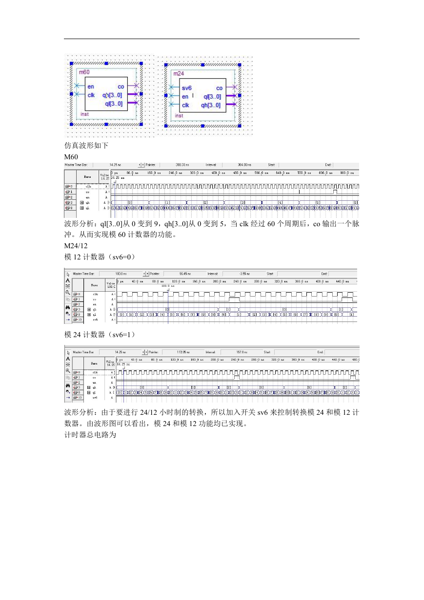
模 60 设计的电路图如下
模 24/12 计数器如下
合成模块分别如下
�
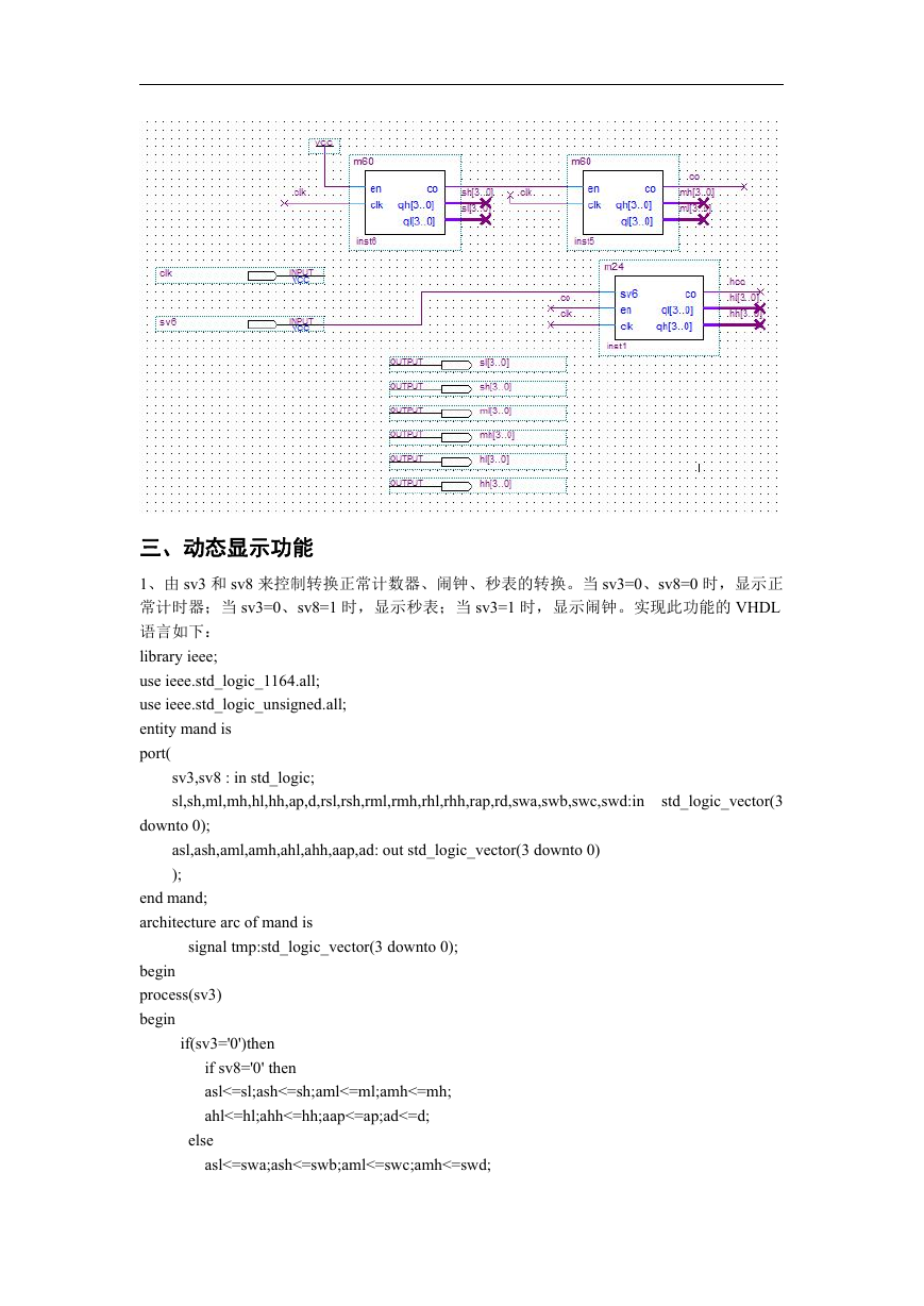
仿真波形如下
M60
波形分析:ql[3..0]从 0 变到 9,qh[3..0]从 0 变到 5,当 clk 经过 60 个周期后,co 输出一个脉
冲。从而实现模 60 计数器的功能。
M24/12
模 12 计数器(sv6=0)
模 24 计数器(sv6=1)
波形分析:由于要进行 24/12 小时制的转换,所以加入开关 sv6 来控制转换模 24 和模 12 计
数器。由波形图可以看出,模 24 和模 12 功能均已实现。
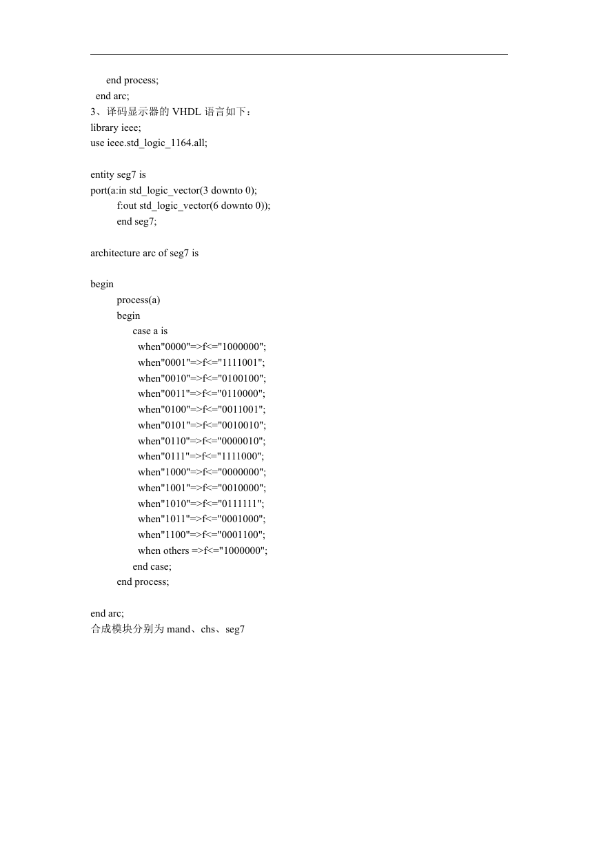
计时器总电路为
�
三、动态显示功能
1、由 sv3 和 sv8 来控制转换正常计数器、闹钟、秒表的转换。当 sv3=0、sv8=0 时,显示正
常计时器;当 sv3=0、sv8=1 时,显示秒表;当 sv3=1 时,显示闹钟。实现此功能的 VHDL
语言如下:
library ieee;
use ieee.std_logic_1164.all;
use ieee.std_logic_unsigned.all;
entity mand is
port(
sv3,sv8 : in std_logic;
sl,sh,ml,mh,hl,hh,ap,d,rsl,rsh,rml,rmh,rhl,rhh,rap,rd,swa,swb,swc,swd:in
std_logic_vector(3
downto 0);
asl,ash,aml,amh,ahl,ahh,aap,ad: out std_logic_vector(3 downto 0)
);
end mand;
architecture arc of mand is
signal tmp:std_logic_vector(3 downto 0);
begin
process(sv3)
begin
if(sv3='0')then
if sv8='0' then
asl<=sl;ash<=sh;aml<=ml;amh<=mh;
ahl<=hl;ahh<=hh;aap<=ap;ad<=d;
else
asl<=swa;ash<=swb;aml<=swc;amh<=swd;
�
ahl<="1010";ahh<="1010";aap<="0000";ad<="1010";
end if;
else
asl<=rsl;ash<=rsh;aml<=rml;amh<=rmh;
ahl<=rhl;ahh<=rhh;aap<=rap;ad<=rd;
if(rap="0010"and rhh="0000" and rhl="0000")then
ahh<="0001";ahl<="0010";
end if;
end if;
end process;
end arc;
2、数据选择器 VHDL 语言描述如下:
library ieee;
use ieee.std_logic_1164.all;
use ieee.std_logic_unsigned.all;
entity chs is
port(
clk : in std_logic;
sl,sh,ml,mh,hl,hh,ap,d:in std_logic_vector(3 downto 0);
data: out std_logic_vector(3 downto 0);
en: out std_logic_vector(7 downto 0)
);
end chs;
architecture arc of chs is
signal tt:std_logic_vector(2 downto 0);
signal t: integer range 0 to 30000;
begin
process(clk)
begin
if(clk'event and clk='1')then
t<=t+1;
if t=30000 then tt<=tt+1;
case tt is
when "000"=>data<=sl;en<="11111110";
when "001"=>data<=sh;en<="11111101";
when "010"=>data<=ml;en<="11111011";
when "011"=>data<=mh;en<="11110111";
when "100"=>data<=hl;en<="11101111";
when "101"=>data<=hh;en<="11011111";
when "110"=>data<=ap+10;en<="10111111";
when "111"=>data<=d;en<="01111111";
end case;
end if;
end if;
�
end process;
end arc;
3、译码显示器的 VHDL 语言如下:
library ieee;
use ieee.std_logic_1164.all;
entity seg7 is
port(a:in std_logic_vector(3 downto 0);
f:out std_logic_vector(6 downto 0));
end seg7;
architecture arc of seg7 is
begin
process(a)
begin
case a is
when"0000"=>f<="1000000";
when"0001"=>f<="1111001";
when"0010"=>f<="0100100";
when"0011"=>f<="0110000";
when"0100"=>f<="0011001";
when"0101"=>f<="0010010";
when"0110"=>f<="0000010";
when"0111"=>f<="1111000";
when"1000"=>f<="0000000";
when"1001"=>f<="0010000";
when"1010"=>f<="0111111";
when"1011"=>f<="0001000";
when"1100"=>f<="0001100";
when others =>f<="1000000";
end case;
end process;
end arc;
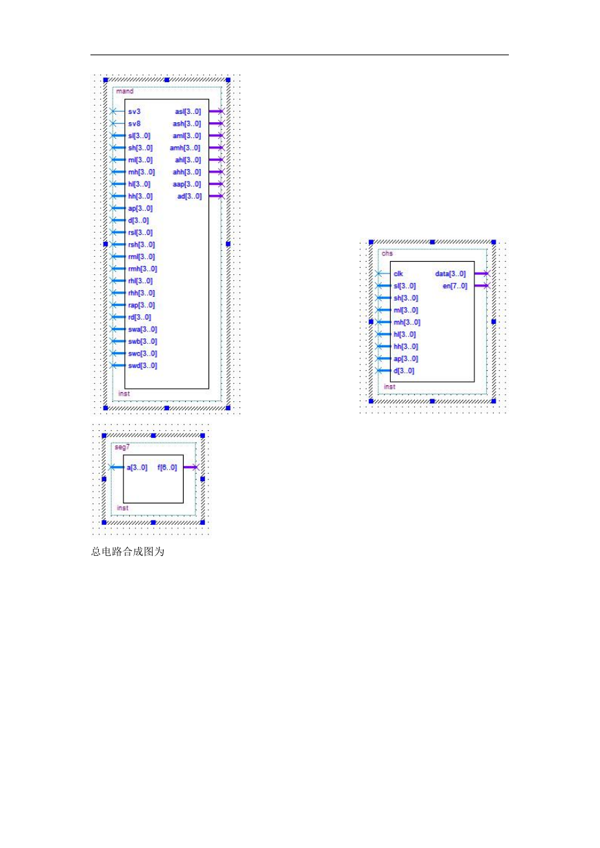
合成模块分别为 mand、chs、seg7
�
总电路合成图为
�


 2023年江西萍乡中考道德与法治真题及答案.doc
 2012年重庆南川中考生物真题及答案.doc
 2013年江西师范大学地理学综合及文艺理论基础考研真题.doc
 2020年四川甘孜小升初语文真题及答案I卷.doc
 2020年注册岩土工程师专业基础考试真题及答案.doc
 2023-2024学年福建省厦门市九年级上学期数学月考试题及答案.doc
 2021-2022学年辽宁省沈阳市大东区九年级上学期语文期末试题及答案.doc
 2022-2023学年北京东城区初三第一学期物理期末试卷及答案.doc
 2018上半年江西教师资格初中地理学科知识与教学能力真题及答案.doc
 2012年河北国家公务员申论考试真题及答案-省级.doc
 2020-2021学年江苏省扬州市江都区邵樊片九年级上学期数学第一次质量检测试题及答案.doc
 2022下半年黑龙江教师资格证中学综合素质真题及答案.doc