From Simulink model to DLL
A tutorial
By
Roland Pfeiffer
Abstract
This document attempts to give a hands-on description on how to make a DLL from a
controller built in Simulink. This makes it possible to develop advanced controllers in
Simulink, and then use them from an arbitrary application.
Persons with knowledge in the C programming language should have no problems
converting the steps in this tutorial to build Linux/Unix libraries, thus expanding the
scope of this document to be applicable not only on Windows.
1
Purpose........................................................................................................................ 2
2 Validity of this document............................................................................................ 2
3
Prerequisites................................................................................................................ 2
Tutorial........................................................................................................................ 2
4
4.1
Preparations......................................................................................................... 2
4.2
Building a controller ........................................................................................... 2
4.3
Generating C code............................................................................................... 3
4.4 Writing a wrapper ............................................................................................... 4
Creating a definition file ..................................................................................... 5
4.5
4.6
Creating the DLL ................................................................................................ 5
5 Using the DLL ............................................................................................................ 6
Source code................................................................................................................. 6
6
grt_shell.c............................................................................................................ 6
Comments on the interface ......................................................................... 6
The code...................................................................................................... 6
controller.def..................................................................................................... 14
Controller.pas.................................................................................................... 14
Comments on the implementation ............................................................ 14
The code.................................................................................................... 14
7 Contact information .................................................................................................. 15
6.3.1
6.3.2
6.1.1
6.1.2
6.1
6.2
6.3
�
From Simulink model to DLL – A tutorial
By Roland Pfeiffer
1 Purpose
The purpose of this document is to describe how to use a controller built in
Matlab/Simulink from other software. The target platform for this tutorial is Windows.
The steps described here should be easily modified to use it on Linux/Unix-platforms. A
description of how the controller built in Simulink can be called from Delphi is also
included.
2 Validity of this document
The method described in this tutorial has not been extensively tested. This means that this
tutorial can contain ambiguities or outright errors. Reports of errors to the author are
much appreciated.
The steps in this tutorial have been performed using Matlab v7 and Simulink v6. It is
quite possible, but not guaranteed, that the tutorial is valid for other versions as well.
3 Prerequisites
It is assumed that the reader is already familiar with Matlab/Simulink. Thus it will not be
described in detail how to build the Simulink model mentioned in this tutorial. It is also
desirable to have some familiarity with the C programming language. However, it should
be possible for anyone with some kind of programming experience to perform the
changes necessary.
It is of course also required to have Matlab/Simulink installed.
4 Tutorial
The following is an attempt to lead the reader from scratch to a dll that can be used from
the software of choice. In several places in this tutorial it is possible to find statements
looking like this ($STATEMENT). These statements (including the braces) are depending
on either the name of the model being used or the platform used. How to replace these
statements should be obvious.
4.1 Preparations
To be able to perform the operations described in later sections it is necessary to add a
few directories into the search path of the computer. Add the following to the path
environment variable:
($MATLABHOME)\rtw\bin\win32
($MATLABHOME)\sys\lcc\bin
Note that ($MATLABHOME) should be replaced with the directory in which Matlab
is installed.
For information on how to change the path variable see the Windows help function.
4.2 Building a controller
The first step is to build a controller in Simulink. The appearance of the controller should
be similar to the one illustrated in Fig. 1.
2
�
From Simulink model to DLL – A tutorial
By Roland Pfeiffer
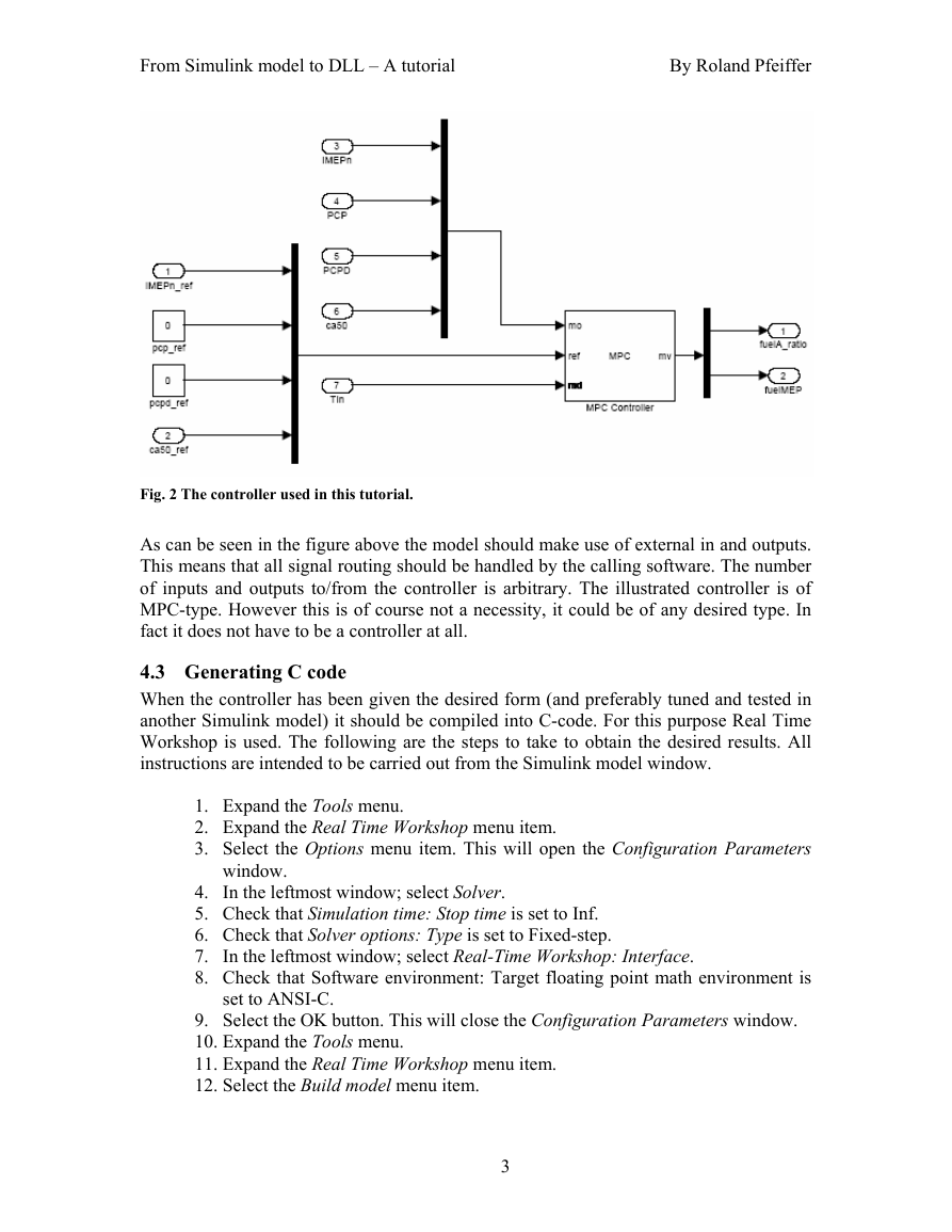
Fig. 2 The controller used in this tutorial.
As can be seen in the figure above the model should make use of external in and outputs.
This means that all signal routing should be handled by the calling software. The number
of inputs and outputs to/from the controller is arbitrary. The illustrated controller is of
MPC-type. However this is of course not a necessity, it could be of any desired type. In
fact it does not have to be a controller at all.
4.3 Generating C code
When the controller has been given the desired form (and preferably tuned and tested in
another Simulink model) it should be compiled into C-code. For this purpose Real Time
Workshop is used. The following are the steps to take to obtain the desired results. All
instructions are intended to be carried out from the Simulink model window.
1. Expand the Tools menu.
2. Expand the Real Time Workshop menu item.
3. Select the Options menu item. This will open the Configuration Parameters
window.
4. In the leftmost window; select Solver.
5. Check that Simulation time: Stop time is set to Inf.
6. Check that Solver options: Type is set to Fixed-step.
7. In the leftmost window; select Real-Time Workshop: Interface.
8. Check that Software environment: Target floating point math environment is
set to ANSI-C.
9. Select the OK button. This will close the Configuration Parameters window.
10. Expand the Tools menu.
11. Expand the Real Time Workshop menu item.
12. Select the Build model menu item.
3
�
From Simulink model to DLL – A tutorial
By Roland Pfeiffer
Assuming that no problems occurred two new directories have been created in the
directory where the model is situated. These two directories are named slrpj and
($NAMEOFSIMULINKMODEL)_grt_rtw.
4.4 Writing a wrapper
The file grt_shell.c (the source code can be viewed in section 6.1) wraps around the
controller developed in Simulink. The original source code generated by Real Time
Workshop contains no functionality that allows it to be called from external functions;
this functionality is provided by this file. It should be noted that the version in section
6.1 is applicable to the example implementation only. This is unless the controller has the
same number of; and name for the inputs and outputs. To work on another controller
(with other inputs and outputs) it has to be modified slightly.
It is not a requirement for the shell functions to look the way they do in this tutorial.
However, it is the author’s opinion that the design chosen here is a good one.
The file grt_shell.c is actually a modified version of the file grt_main.c which can be
found in ($MATLABHOME)\rtw\c\grt. In most cases it should be sufficient to modify
the existing version of grt_shell.c. If mere modifications do not suffice; a new version of
the file will have to be written. Such a procedure is not described in this tutorial but
should be possible to achieve by studying example file supplied here.
The following list contains the steps to take to modify grt_main.c to use x inputs
named in_1, in_2 … in_x and y outputs named out_1, out_2 … out_y.
1 A structure for handling data in the C programming language
4
1. Open the file grt_shell.c in your favorite text editor.
2. locate the function getControllerOutput.
3. Alter the lines checking the number of input and output arguments. Instead of
checking that the number of inputs are 7 and the number of outputs are 2, they
should instead test that the number of inputs are x and the number of outputs
are y.
4. This function makes use of a struct1 called ($NAMEOFMODEL)_U. This
struct handles the inputs to the model. For the example implementation the
inputs are called IMEPn_ref, ca50_ref and so on. These lines should be altered
to look something like this:
($NAMEOFMODEL)_U.in_1 = inputs[0];
($NAMEOFMODEL)_U.in_2 = inputs[1];
…
($NAMEOFMODEL)_U.in_x = inputs[x-1];
It is important to keep track of what order the input arguments are given since
they only have numbers and no names.
5. Close to the end of the same function the outputs from the calculations are
entered into the output array. As with the inputs; the outputs are stored in a
struct, for the outputs the name of the struct is ($NAMEOFMODEL)_Y. The
elements of this struct have the names of the outputs in the Simulink model.
This means that the lines assigning values to the output array should be
changed to look like as follows:
outputs[0] = ($NAMEOFMODEL)_Y.out_1;
�
From Simulink model to DLL – A tutorial
By Roland Pfeiffer
outputs[1] = ($NAMEOFMODEL)_Y.out_2;
…
outputs[y-1] = ($NAMEOFMODEL)_Y.out_y;
As with the inputs it is important to keep track of the order in which the
outputs are entered into the output array.
6. At this point the file should be modified to suit the new configuration. Save it
and go on to the next section.
4.5 Creating a definition file
When creating a DLL it is necessary to make use of a definition file where the functions
to be exported are listed. In this case only three functions are exported and unless the
function declarations in grt_shell.c are altered the content of controller.def will not have
to be changed. The definition file for the example implementation is located in section
6.2.
4.6 Creating the DLL
At this point the controller built in Simulink has been compiled into C-code. The next
step is to add some functions making the resulting DLL usable. Following is a list of
steps to take to build the DLL
1. Copy the file grt_shell.c into the ($NAMEOFMODEL)_grt_rtw directory.
2. Copy the file controller.def into the ($NAMEOFMODEL)_grt_rtw directory.
3. Open a command prompt.
4. In the command prompt go to the controller_grt_rtw directory.
5. Enter the command gmake –f ($NAMEOFMODEL).mk. This will compile the
generated C code into an executable with the same name as the Simulink
model. It will also generate object files which will be used later steps.
6. Look at the text written to the command window by the command given in the
previous step. Written to the command prompt are the commands that gmake
used to compile and link the executable mentioned above. Locate the
command starting with ($SOMEPATH)\lcc –c -Fogrt_main.obj and ending
with ($ANOTHERPATH)\grt_main.c. Copy this command and alter it to start
with lcc –c -Fogrt_main.obj and end with grt_shell.c. Enter this command in
the command prompt. This will create a new version of the objective file
grt_main.obj.
7. Now it is time to perform the linking creating the actual DLL. To do this,
locate the last command given by gmake. This command should start with
($SOMEPATH)\lcclnk –s and end with ($ANOTHERPATH)\rtwlib_lcc.lib.
Begin by altering the start from ($SOMEPATH)\lcclnk to lcclnk.
8. Some distance into this command it is possible to find the following –o
..\($NAMEOFMODEL).exe ($NAMEOFMODEL).obj. Replace this with the
following instead –dll ($NAMEOFMODEL).obj.
9. At the end of the command; add controller.def.
10. Run the command. This command will link the object files created in previous
steps to a DLL called controller.dll.
5
�
From Simulink model to DLL – A tutorial
By Roland Pfeiffer
5 Using the DLL
The DLL created in previous sections can be used from the programming language of the
user’s choice. Even though the DLL can be used in code from several programming
languages it has been tested only from Delphi.
An example implementation of how to use the DLL from Delphi can be viewed in
section 6.3.
It should be noted that the C compiler will rename the functions in grt_shell.c. This
means that the function name func() will be changed to _func() in the DLL.
6 Source code
This section contains the source for the files mentioned previously.
6.1 grt_shell.c
This is the wrapper file creating a user friendly user interface.
6.1.1 Comments on the interface
The interface of grt_shell.c contains three functions:
char* initiateController();
char* getControllerOutput(int nbrInputArgs, double*
inputArgs, int nbrOutputArgs,
char* performCleanup();
double* outputArgs);
Each of the functions returns pointers to a character array. They all return an empty
pointer if no error occurred during the function call. If an error has occurred, the pointer
will point to a character array containing a description of the error.
Function 1 performs initiation of the controller. This function must be called before
any other function is called.
Function 2 performs the controller calculations. This is the function to call once every
sample. Both inputs and outputs are supplied by the caller in the form of pointers to
arrays.
Function 3 performs cleanup. This function should be called before closing the
application.
6.1.2 The code
/*
* Modified version of grt_main.c
* Modifications made by Roland Pfeiffer
*/
/* $Revision: 1.68.4.6 $
* Copyright 1994-2004 The MathWorks, Inc.
*
* File : grt_main.c
*
* Abstract:
* A Generic "Real-Time (single tasking or pseudo-multitasking,
* statically allocated data)" main that runs under most
* operating systems.
6
�
From Simulink model to DLL – A tutorial
By Roland Pfeiffer
Default is .mat
RT - Required.
NUMST=# - Required. Number of sample times.
NCSTATES=# - Required. Number of continuous states.
*
* This file may be a useful starting point when targeting a new
* processor or microcontroller.
*
*
* Compiler specified defines:
*
* MODEL=modelname - Required.
*
*
* TID01EQ=1 or 0 - Optional. Only define to 1 if sample time
task
* id's 0 and 1 have equal rates.
* MULTITASKING - Optional. (use MT for a synonym).
SAVEFILE - Optional (non-quoted) name of .mat file to
*
create.
*
* BORLAND - Required if using Borland C/C++
*/
#include
#include
#include
#include
#include
#include "tmwtypes.h"
# include "rtmodel.h"
#include "rt_sim.h"
#include "rt_logging.h"
#ifdef UseMMIDataLogging
#include "rt_logging_mmi.h"
#endif
#include "rt_nonfinite.h"
/* Signal Handler header */
#ifdef BORLAND
#include
#include
#endif
#include "ext_work.h"
/*=========*
* Defines *
*=========*/
#ifndef TRUE
#define FALSE (0)
#define TRUE (1)
#endif
#ifndef EXIT_FAILURE
#define EXIT_FAILURE 1
#endif
#ifndef EXIT_SUCCESS
#define EXIT_SUCCESS 0
7
�
From Simulink model to DLL – A tutorial
By Roland Pfeiffer
#endif
#define QUOTE1(name) #name
#define QUOTE(name) QUOTE1(name) /* need to expand name */
#ifndef RT
# error "must define RT"
#endif
#ifndef MODEL
# error "must define MODEL"
#endif
#ifndef NUMST
# error "must define number of sample times, NUMST"
#endif
#ifndef NCSTATES
# error "must define NCSTATES"
#endif
#ifndef SAVEFILE
# define MATFILE2(file) #file ".mat"
# define MATFILE1(file) MATFILE2(file)
# define MATFILE MATFILE1(MODEL)
#else
# define MATFILE QUOTE(SAVEFILE)
#endif
#define RUN_FOREVER -1.0
#define EXPAND_CONCAT(name1,name2) name1 ## name2
#define CONCAT(name1,name2) EXPAND_CONCAT(name1,name2)
#define RT_MODEL CONCAT(MODEL,_rtModel)
/*====================*
* External functions *
*====================*/
extern RT_MODEL *MODEL(void);
extern void MdlInitializeSizes(void);
extern void MdlInitializeSampleTimes(void);
extern void MdlStart(void);
extern void MdlOutputs(int_T tid);
extern void MdlUpdate(int_T tid);
extern void MdlTerminate(void);
#if NCSTATES > 0
extern void rt_ODECreateIntegrationData(RTWSolverInfo *si);
extern void rt_ODEUpdateContinuousStates(RTWSolverInfo *si);
# define rt_CreateIntegrationData(S) \
rt_ODECreateIntegrationData(rtmGetRTWSolverInfo(S));
# define rt_UpdateContinuousStates(S) \
rt_ODEUpdateContinuousStates(rtmGetRTWSolverInfo(S));
# else
8
�



 2023年江西萍乡中考道德与法治真题及答案.doc
 2012年重庆南川中考生物真题及答案.doc
 2013年江西师范大学地理学综合及文艺理论基础考研真题.doc
 2020年四川甘孜小升初语文真题及答案I卷.doc
 2020年注册岩土工程师专业基础考试真题及答案.doc
 2023-2024学年福建省厦门市九年级上学期数学月考试题及答案.doc
 2021-2022学年辽宁省沈阳市大东区九年级上学期语文期末试题及答案.doc
 2022-2023学年北京东城区初三第一学期物理期末试卷及答案.doc
 2018上半年江西教师资格初中地理学科知识与教学能力真题及答案.doc
 2012年河北国家公务员申论考试真题及答案-省级.doc
 2020-2021学年江苏省扬州市江都区邵樊片九年级上学期数学第一次质量检测试题及答案.doc
 2022下半年黑龙江教师资格证中学综合素质真题及答案.doc