Seminar: Gain Without Pain
November 2000
RF Predistortion of Power Amplifiers
Shawn Stapleton
Agilent Technologies
1400 Fountaingrove Parkway
Santa Rosa, CA 95403
1
�
Abstract
With the advent of linear modulation methods, linearization of power amplifiers has become an
important technology. The adaptive work function predistorter is an approach to optimizing
out-of-band intermodulation performance. This technique can adapt to changes in the power
amplifier’s characteristics, including effects such as temperature changes, channel switching,
power supply variation, and transistor degradation. The technique can also handle larger
bandwidths than current DSP-based digital predistorters.
Biography
Dr. Shawn P. Stapleton has 17 years of experience in the design of RF and microwave circuits
and systems. He is presently professor of electrical engineering at Simon Fraser University as
well as a consultant for Agilent EEsof. He has developed GaAs MMIC components, including
mixers, amplifiers, frequency dividers and oscillators. His most recent work includes digital
signal processing, mobile communications and RF/microwave systems.
2
�
Agenda & Topics
RF Predistortion of Power Amplifiers
Introduction to Adaptive RF Predistortion
Key Features: RF Predistortion Techniques & Concepts
RF Predistortion Design Example
Conclusion
3
This section of the workshop provides an introduction to predistortion. We will cover key
features, technologies, and performance issues. Approaches to solving some of the design
challenges will also be presented. An adaptive work function based predistorter is
demonstrated using the Agilent Advanced Design System. Additional reference
information is also available.
3
�
Technology Overview
Linearization approaches:
FeedForward Linearization
– Based on inherently wideband technology
Digital Predistortion
– Limited Bandwidth (DSP implementation)
Cartesian Feedback
– Stability considerations limit bandwidth and accuracy
LINC
– Sensitive to component drift and has a high level of complexity
Dynamic Biasing
– Limited ACI suppression
RF-Based Predistortion
– Limited accuracy of function model
– Implemented at RF with low complexity
– Adaptation is required
4
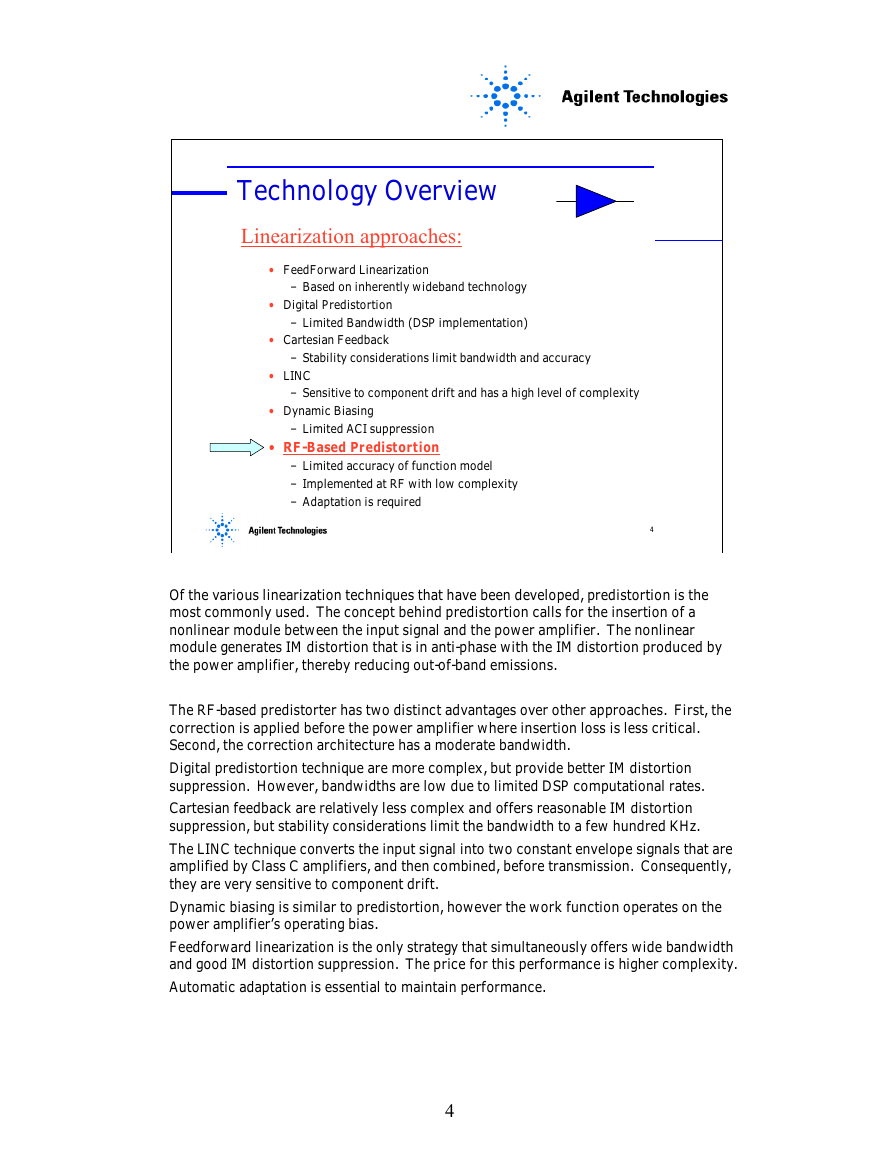
Of the various linearization techniques that have been developed, predistortion is the
most commonly used. The concept behind predistortion calls for the insertion of a
nonlinear module between the input signal and the power amplifier. The nonlinear
module generates IM distortion that is in anti-phase with the IM distortion produced by
the power amplifier, thereby reducing out-of-band emissions.
The RF-based predistorter has two distinct advantages over other approaches. First, the
correction is applied before the power amplifier where insertion loss is less critical.
Second, the correction architecture has a moderate bandwidth.
Digital predistortion technique are more complex, but provide better IM distortion
suppression. However, bandwidths are low due to limited DSP computational rates.
Cartesian feedback are relatively less complex and offers reasonable IM distortion
suppression, but stability considerations limit the bandwidth to a few hundred KHz.
The LINC technique converts the input signal into two constant envelope signals that are
amplified by Class C amplifiers, and then combined, before transmission. Consequently,
they are very sensitive to component drift.
Dynamic biasing is similar to predistortion, however the work function operates on the
power amplifier’s operating bias.
Feedforward linearization is the only strategy that simultaneously offers wide bandwidth
and good IM distortion suppression. The price for this performance is higher complexity.
Automatic adaptation is essential to maintain performance.
4
�
RF-Based Predistortion
Power Amplifier
RF input
Delay
Complex Gain
Adjuster
I
Q
Work Function
or Look-up
Table
Envelope Detector
DSP
Optimization of
Parameters
RF Output
Out of Band
Filter
Power Detector
5
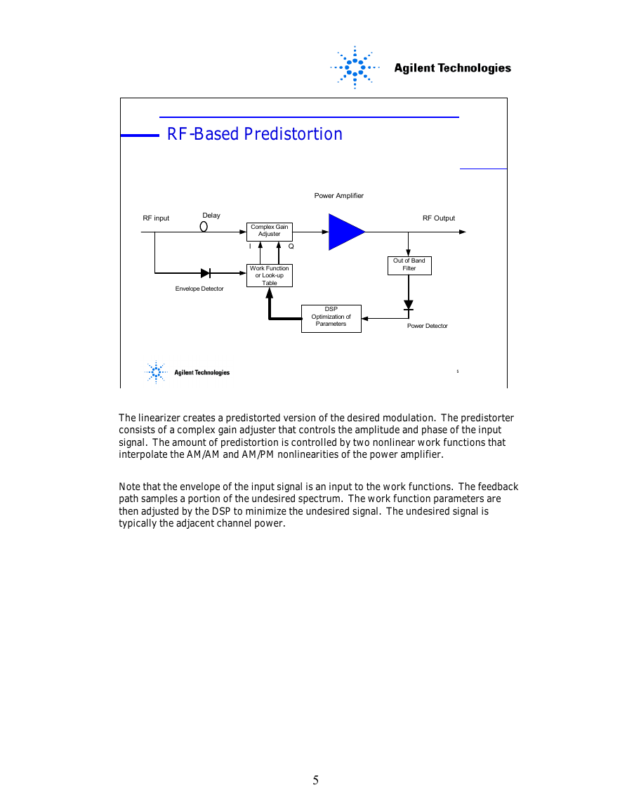
The linearizer creates a predistorted version of the desired modulation. The predistorter
consists of a complex gain adjuster that controls the amplitude and phase of the input
signal. The amount of predistortion is controlled by two nonlinear work functions that
interpolate the AM/AM and AM/PM nonlinearities of the power amplifier.
Note that the envelope of the input signal is an input to the work functions. The feedback
path samples a portion of the undesired spectrum. The work function parameters are
then adjusted by the DSP to minimize the undesired signal. The undesired signal is
typically the adjacent channel power.
5
�
Spectrum at the Nodes
RF input
Delay
Complex Gain
Adjuster
I
Q
Power Amplifier
RF Output
Work Function
or Look-up
Table
Envelope Detector
DSP
Optimization of
Parameters
Out of Band
Filter
Power Detector
6
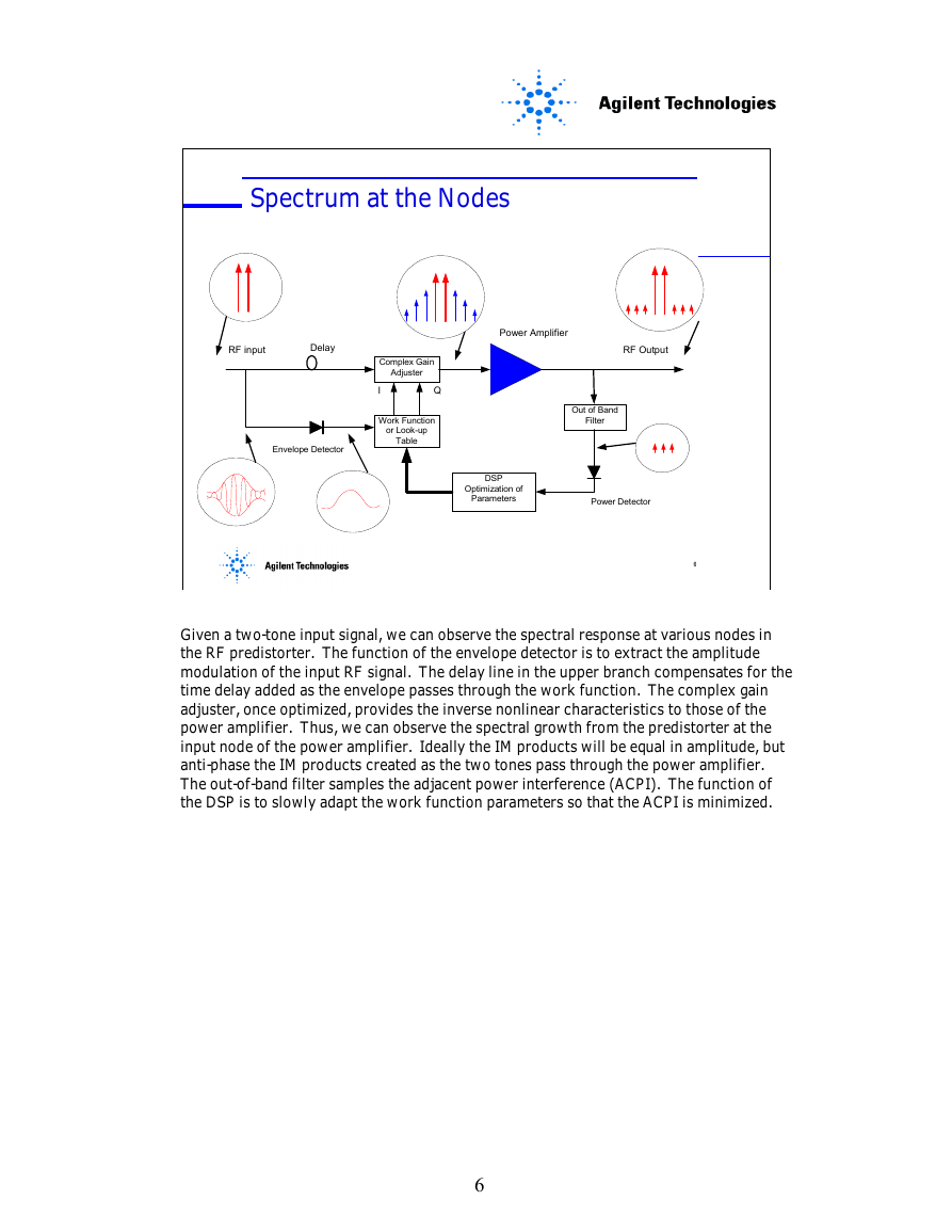
Given a two-tone input signal, we can observe the spectral response at various nodes in
the RF predistorter. The function of the envelope detector is to extract the amplitude
modulation of the input RF signal. The delay line in the upper branch compensates for the
time delay added as the envelope passes through the work function. The complex gain
adjuster, once optimized, provides the inverse nonlinear characteristics to those of the
power amplifier. Thus, we can observe the spectral growth from the predistorter at the
input node of the power amplifier. Ideally the IM products will be equal in amplitude, but
anti-phase the IM products created as the two tones pass through the power amplifier.
The out-of-band filter samples the adjacent power interference (ACPI). The function of
the DSP is to slowly adapt the work function parameters so that the ACPI is minimized.
6
�
Design Techniques
RF-Based Predistortion
Generic RF predistortion techniques
– Work function (I.e. polynomial, exponential)
– Look-up table
– Analog nonlinearity (I.e. Diodes)
Generic adaptation techniques...
– ACI power minimization
– Gradient evaluation
7
In the mid-’80s and early ’90s, many patents were filed covering adaptive predistortion.
These patents encompass two general adaptation methods—adaptation based on power
minimization and adaptation based on gradient signals.
The control scheme for power-minimization adaptation is based on trying to adjust the
complex gain adjuster to minimize the measured power of the error signal in the out-of-
band frequency. Once the optimum parameters have been achieved, deliberate
perturbations are required to continuously update the coefficients, which reduces the
effects of IM distortion suppression.
Adaptation based on the use of gradient signals requires a continuous computation to
estimate the gradient of a three-dimensional power surface. The surface for the RF
predistorter circuit is the difference between the input signal and the scaled output signal.
This power is minimized when the error signal is completely suppressed. Since the
gradient is continually updated, no deliberate misadjustment is required.
There are three distinct RF predistortion techniques.
The work function-based approach utilizes a low-order polynomial to fit the AM/AM and
AM/PM characteristics of the power amplifier.
The look-up table technique fits the power amplifier’s characteristics more accurately.
However, it requires a more sophisticated adaptation technique.
The analog nonlinearity technique uses diodes to generate IM distortion. This IM
distorition is then phased and attenuated to make it anti-phase with the distortion created
by the power amplifier.
7
�
Rectangular Work Function Predistorter
Power Amplifier
RF input
Delay
Complex Gain
Adjuster
I
Q
Work Function
or Look-up
Table
Envelope Detector
DSP
Optimization of
Parameters
I
Q
) + j F F22((ρρρρρρρρ))
Rectangular Gain Function
Rectangular Gain Function
F(F(ρρρρρρρρ) = F) = F11((ρρρρρρρρ) + j
FF11((ρρρρρρρρ) = (1+G
FF22((ρρρρρρρρ) = (1+P
ρρρρρρρρ is squared envelope
is squared envelope
Delay
) = (1+G1 1 ρρρρρρρρ+G+G2 2 ρρρρρρρρ22))
) = (1+P1 1 ρρρρρρρρ+P+P2 2 ρρρρρρρρ22))
ρρρρρρρρ
LPF
Envelope
Detector
From DSP
G1
G2
P1
P2
RF Output
Out of Band
Filter
Power Detector
8
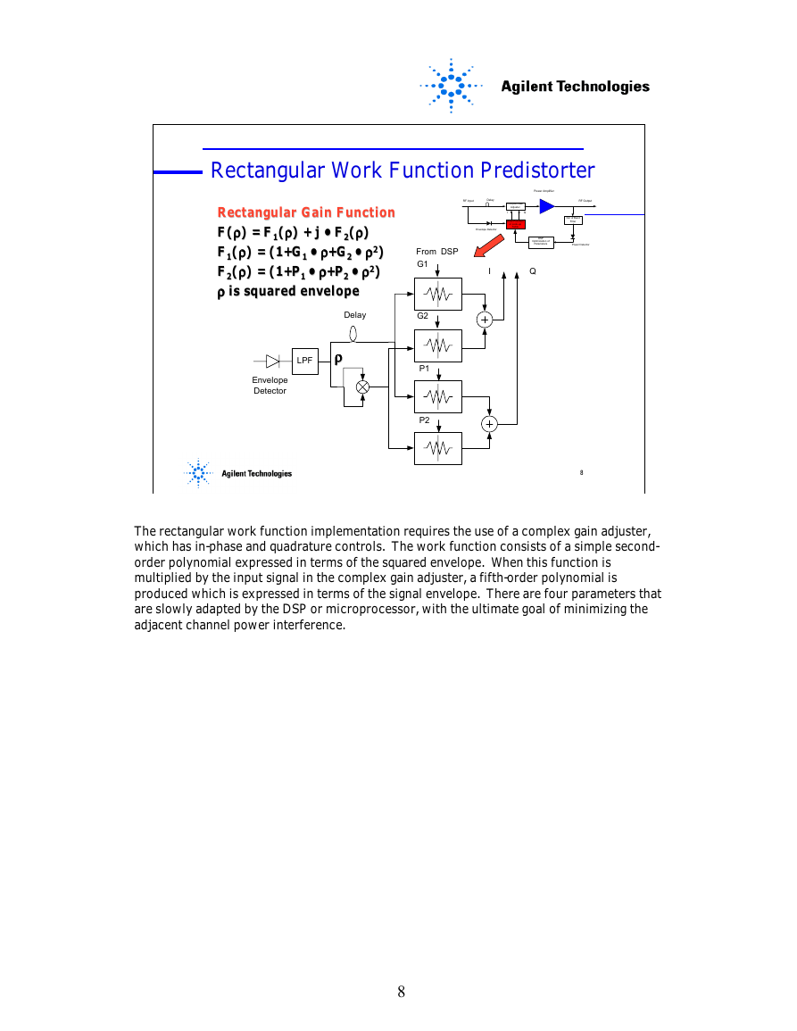
The rectangular work function implementation requires the use of a complex gain adjuster,
which has in-phase and quadrature controls. The work function consists of a simple second-
order polynomial expressed in terms of the squared envelope. When this function is
multiplied by the input signal in the complex gain adjuster, a fifth-order polynomial is
produced which is expressed in terms of the signal envelope. There are four parameters that
are slowly adapted by the DSP or microprocessor, with the ultimate goal of minimizing the
adjacent channel power interference.
8
�





 2023年江西萍乡中考道德与法治真题及答案.doc
 2012年重庆南川中考生物真题及答案.doc
 2013年江西师范大学地理学综合及文艺理论基础考研真题.doc
 2020年四川甘孜小升初语文真题及答案I卷.doc
 2020年注册岩土工程师专业基础考试真题及答案.doc
 2023-2024学年福建省厦门市九年级上学期数学月考试题及答案.doc
 2021-2022学年辽宁省沈阳市大东区九年级上学期语文期末试题及答案.doc
 2022-2023学年北京东城区初三第一学期物理期末试卷及答案.doc
 2018上半年江西教师资格初中地理学科知识与教学能力真题及答案.doc
 2012年河北国家公务员申论考试真题及答案-省级.doc
 2020-2021学年江苏省扬州市江都区邵樊片九年级上学期数学第一次质量检测试题及答案.doc
 2022下半年黑龙江教师资格证中学综合素质真题及答案.doc