Serial ATA:
High Speed Serialized AT Attachment
Revision 1.0a
7-January-2003
APT Technologies, Inc.
Dell Computer Corporation
Intel Corporation
Maxtor Corporation
Seagate Technology
�
HIGH SPEED SERIALIZED AT ATTACHMENT
SerialATA Workgroup
This 1.0a revision of the Serial ATA / High Speed Serialized AT Attachment specification consists
of the 1.0 revision of the specification with the following errata incorporated:
Page: 1
2, 3, 4, 5, 6, 7, 8, 9, 10, 11, 12, 13, 14, 15, 16, 17, 18, 19, 20, 21, 22, 23, 24, 25, 26, 29,
30, 31, 32, 33, 34, 35, 36, 38, 40
The following errata were withdrawn and were not incorporated into this revision of the
specification:
1, 27, 28
Details on individual errata can be downloaded from the Serial ATA Working Group website at
www.serialata.org.
This 1.0a revision of the Serial ATA / High Speed Serialized AT Attachment specification (“Final
Specification”) is available for product design. Product implementations should ensure
compliance with this specification.
SPECIFICATION DISCLAIMER
“AS
IS PROVIDED TO YOU
IS” WITH NO WARRANTIES
THIS SPECIFICATION
WHATSOEVER,
INCLUDING ANY WARRANTY OF MERCHANTABILITY, NON-
INFRINGEMENT, OR FITNESS FOR ANY PARTICULAR PURPOSE. THE AUTHORS OF THIS
SPECIFICATION DISCLAIM ALL LIABILITY, INCLUDING LIABILITY FOR INFRINGEMENT OF
ANY PROPRIETARY RIGHTS, RELATING TO USE OR IMPLEMENTATION OF INFORMATION
IN THIS SPECIFICATION. THE AUTHORS DO NOT WARRANT OR REPRESENT THAT SUCH
USE WILL NOT INFRINGE SUCH RIGHTS. THE PROVISION OF THIS SPECIFICATION TO
YOU DOES NOT PROVIDE YOU WITH ANY LICENSE, EXPRESS OR IMPLIED, BY
ESTOPPEL OR OTHERWISE, TO ANY INTELLECTUAL PROPERTY RIGHTS.
Copyright 2000, 2001, 2002, 2003, APT Technologies, Inc., Dell Computer Corporation, Intel
Corporation, Maxtor Corporation, Seagate Technology LLC. All rights reserved.
For more information about Serial ATA, refer to the Serial ATA Working Group website at
www.serialata.org.
All product names are trademarks, registered trademarks, or servicemarks of their respective
owners.
Serial ATA Workgroup Technical Editor:
Klaus-Peter Deyring
APT Technologies, Inc.
1347 Pacific Avenue
Suite 205
Santa Cruz, CA 95060 USA
Tel: 831-429-7262
Fax: 831-429-7272
Email: pete@apt-tech.com
�
HIGH SPEED SERIALIZED AT ATTACHMENT
SerialATA Workgroup
Serial ATA Workgroup
Promoters
Page: 2
Klaus-Peter Deyring
(831) 429-7262
pete@apt-tech.com
APT Technologies, Inc.
1347 Pacific Avenue
Suite 205
Santa Cruz, CA 95060
Tom Pratt
(512) 723-8549
tom_pratt@dell.com
Dell Computer Corp.
One Dell Way
Round Rock, TX 78682
Knut Grimsrud
(503) 264-8419
knut.s.grimsrud@intel.com
Intel Corp.
M/S JF2-53
2111 NE 25th Ave
Hillsboro, OR 97124
Farbod Falakfarsa
(408) 894-4066
PTD Architecture Group
500 McCarthy Blvd
Milpitas, CA 95035
Farbod.Falakfarsa@maxtor.com
Marc Noblitt
I/O Planning manager
(720) 684-1333 phone
(720) 684-1031 fax
marc_noblitt@seagate.com
Seagate Technology
389 Disc Drive
Longmont, CO 80503
�
HIGH SPEED SERIALIZED AT ATTACHMENT
SerialATA Workgroup
Page: 3
TABLE OF CONTENTS
1
Scope..................................................................................................................................... 11
2 Goals, objectives and migration considerations.................................................................... 11
Goals and objectives ..................................................................................................... 11
2.1
2.2 Migration Considerations............................................................................................... 12
3 Normative references ............................................................................................................ 13
3.1
Approved references ..................................................................................................... 13
Other references............................................................................................................ 13
3.2
4 Definitions, abbreviations, and conventions .......................................................................... 13
Definitions and abbreviations ........................................................................................ 13
4.1
ATA (AT Attachment)............................................................................................. 13
4.1.1
ATAPI (AT Attachment Packet Interface) device .................................................. 13
4.1.2
backchannel........................................................................................................... 14
4.1.3
bit synchronization................................................................................................. 14
4.1.4
byte ........................................................................................................................ 14
4.1.5
character................................................................................................................ 14
4.1.6
character alignment ............................................................................................... 14
4.1.7
character slipping................................................................................................... 14
4.1.8
code violation......................................................................................................... 14
4.1.9
comma character................................................................................................... 14
4.1.10
comma sequence .................................................................................................. 14
4.1.11
command aborted.................................................................................................. 15
4.1.12
4.1.13
command completion............................................................................................. 15
command packet ................................................................................................... 15
4.1.14
4.1.15 Control Block registers........................................................................................... 15
4.1.16
control character.................................................................................................... 15
control variable ...................................................................................................... 15
4.1.17
4.1.18 CRC ....................................................................................................................... 15
4.1.19
data character........................................................................................................ 15
4.1.20
device..................................................................................................................... 15
4.1.21 DMA (direct memory access) ................................................................................ 15
4.1.22 Dword..................................................................................................................... 16
4.1.23 Dword synchronization .......................................................................................... 16
4.1.24
encoded character................................................................................................. 16
elasticity buffer....................................................................................................... 16
4.1.25
First-party DMA access ......................................................................................... 16
4.1.26
4.1.27
First-party DMA mode............................................................................................ 16
4.1.28
FIS ......................................................................................................................... 16
Frame Information Structure.................................................................................. 16
4.1.29
frame...................................................................................................................... 16
4.1.30
4.1.31
interrupt pending.................................................................................................... 17
4.1.32
legacy device ......................................................................................................... 17
4.1.33
legacy mode .......................................................................................................... 17
4.1.34
legal character ....................................................................................................... 17
LFSR...................................................................................................................... 17
4.1.35
4.1.36 PIO (programmed input/output)............................................................................. 17
4.1.37
primitive.................................................................................................................. 17
sector ..................................................................................................................... 17
4.1.38
4.1.39 Shadow Register Block registers........................................................................... 17
4.1.40
unrecoverable error ............................................................................................... 17
4.1.41 word ....................................................................................................................... 17
Conventions................................................................................................................... 18
Precedence............................................................................................................ 18
4.2.1
Keywords ............................................................................................................... 18
4.2.2
4.2
�
HIGH SPEED SERIALIZED AT ATTACHMENT
SerialATA Workgroup
Page: 4
6
5.1
5.2
6.1
6.2
6.3
4.2.3
4.2.4
4.2.5
4.2.6
4.2.7
4.2.8
Numbering ............................................................................................................. 19
Signal conventions................................................................................................. 19
Bit conventions ...................................................................................................... 19
State diagram conventions .................................................................................... 20
Timing conventions................................................................................................ 21
Byte, word and Dword Relationships..................................................................... 22
5 General overview................................................................................................................... 23
Sub-module operation ................................................................................................... 25
Standard ATA Emulation ............................................................................................... 26
Software Reset ...................................................................................................... 26
5.2.1
Master-only emulation ........................................................................................... 26
5.2.2
Master/Slave emulation (optional)......................................................................... 27
5.2.3
Standard ATA interoperability state diagrams....................................................... 29
5.2.4
IDENTIFY DEVICE command ............................................................................... 33
5.2.5
Physical layer......................................................................................................................... 36
Overview........................................................................................................................ 36
List of services............................................................................................................... 36
Cables and connectors specifications ........................................................................... 37
6.3.1
Overview................................................................................................................ 37
6.3.2
Objectives .............................................................................................................. 37
6.3.3
General descriptions.............................................................................................. 37
6.3.4
Connector configurations and locations ................................................................ 40
6.3.5
Mating interfaces ................................................................................................... 43
6.3.6
Serial ATA cable.................................................................................................... 56
6.3.7
Backplane connector configuration and blind-mating tolerance............................ 56
6.3.8
Connector labeling................................................................................................. 57
6.3.9
Connector and cable assembly requirements and test procedures ...................... 57
Low level electronics block diagram.............................................................................. 68
6.4.1
Diagram ................................................................................................................. 68
6.4.2
Physical plant overall block diagram description................................................... 69
6.4.3
Analog front end (AFE) block diagram description................................................ 72
6.5
General specifications ................................................................................................... 73
6.5.1
System................................................................................................................... 73
6.6 Module specifications .................................................................................................... 74
6.6.1
Definitions .............................................................................................................. 74
6.6.2
Electrical specifications.......................................................................................... 74
6.6.3
Differential voltage/timing (EYE) diagram............................................................. 78
6.6.4
Sampling jitter specifications ................................................................................. 79
Functional specifications................................................................................................ 86
6.7.1
Overview................................................................................................................ 86
6.7.2
Common-mode biasing.......................................................................................... 86
6.7.3
Matching ................................................................................................................ 88
6.7.4
Out of band signaling............................................................................................. 88
6.7.5
Idle bus condition................................................................................................... 97
6.7.6
Elasticity buffer management ................................................................................ 97
Test considerations................................................................................................ 98
6.7.7
Interface power states ................................................................................................. 117
6.8.1
Interface power state sequences......................................................................... 118
Link layer ............................................................................................................................. 129
Overview.............................................................................................................. 129
7.1.1
Encoding method......................................................................................................... 129
7.2.1
Notation and conventions .................................................................................... 129
Character code .................................................................................................... 131
7.2.2
Transmission summary........................................................................................ 139
7.2.3
7.2.4
Reception summary............................................................................................. 141
Transmission overview ................................................................................................ 142
7
6.8
7.2
6.4
6.7
7.3
�
HIGH SPEED SERIALIZED AT ATTACHMENT
SerialATA Workgroup
Page: 5
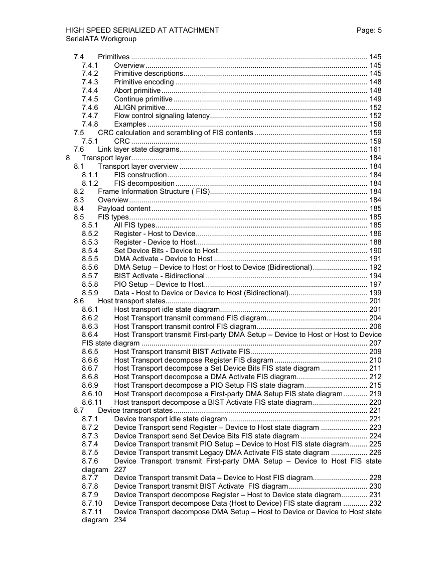
7.4
7.5
7.6
8.1
8.2
8.3
8.4
8.5
Primitives ..................................................................................................................... 145
Overview.............................................................................................................. 145
7.4.1
Primitive descriptions........................................................................................... 145
7.4.2
Primitive encoding ............................................................................................... 148
7.4.3
Abort primitive...................................................................................................... 148
7.4.4
Continue primitive................................................................................................ 149
7.4.5
ALIGN primitive.................................................................................................... 152
7.4.6
Flow control signaling latency.............................................................................. 152
7.4.7
Examples ............................................................................................................. 156
7.4.8
CRC calculation and scrambling of FIS contents ........................................................ 159
7.5.1
CRC ..................................................................................................................... 159
Link layer state diagrams............................................................................................. 161
Transport layer..................................................................................................................... 184
Transport layer overview ............................................................................................. 184
FIS construction................................................................................................... 184
8.1.1
FIS decomposition............................................................................................... 184
8.1.2
Frame Information Structure ( FIS).............................................................................. 184
Overview...................................................................................................................... 184
Payload content........................................................................................................... 185
FIS types...................................................................................................................... 185
All FIS types......................................................................................................... 185
8.5.1
Register - Host to Device..................................................................................... 186
8.5.2
Register - Device to Host..................................................................................... 188
8.5.3
Set Device Bits - Device to Host.......................................................................... 190
8.5.4
DMA Activate - Device to Host ............................................................................ 191
8.5.5
DMA Setup – Device to Host or Host to Device (Bidirectional)........................... 192
8.5.6
BIST Activate - Bidirectional ................................................................................ 194
8.5.7
PIO Setup – Device to Host................................................................................. 197
8.5.8
Data - Host to Device or Device to Host (Bidirectional)....................................... 199
8.5.9
Host transport states.................................................................................................... 201
Host transport idle state diagram......................................................................... 201
8.6.1
Host Transport transmit command FIS diagram.................................................. 204
8.6.2
8.6.3
Host Transport transmit control FIS diagram....................................................... 206
8.6.4
Host Transport transmit First-party DMA Setup – Device to Host or Host to Device
FIS state diagram ................................................................................................................ 207
8.6.5
Host Transport transmit BIST Activate FIS.......................................................... 209
Host Transport decompose Register FIS diagram .............................................. 210
8.6.6
Host Transport decompose a Set Device Bits FIS state diagram ....................... 211
8.6.7
8.6.8
Host Transport decompose a DMA Activate FIS diagram................................... 212
8.6.9
Host Transport decompose a PIO Setup FIS state diagram............................... 215
8.6.10 Host Transport decompose a First-party DMA Setup FIS state diagram............ 219
8.6.11 Host transport decompose a BIST Activate FIS state diagram........................... 220
Device transport states................................................................................................ 221
8.7.1
Device transport idle state diagram..................................................................... 221
Device Transport send Register – Device to Host state diagram ....................... 223
8.7.2
Device Transport send Set Device Bits FIS state diagram ................................. 224
8.7.3
8.7.4
Device Transport transmit PIO Setup – Device to Host FIS state diagram......... 225
Device Transport transmit Legacy DMA Activate FIS state diagram .................. 226
8.7.5
8.7.6
Device Transport transmit First-party DMA Setup – Device to Host FIS state
diagram 227
Device Transport transmit Data – Device to Host FIS diagram........................... 228
8.7.7
Device Transport transmit BIST Activate FIS diagram....................................... 230
8.7.8
Device Transport decompose Register – Host to Device state diagram............. 231
8.7.9
8.7.10 Device Transport decompose Data (Host to Device) FIS state diagram ............ 232
8.7.11 Device Transport decompose DMA Setup – Host to Device or Device to Host state
diagram 234
8.6
8.7
8
�
HIGH SPEED SERIALIZED AT ATTACHMENT
SerialATA Workgroup
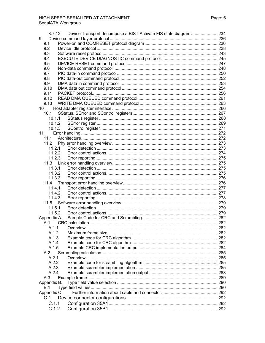
Page: 6
10
11
8.7.12 Device Transport decompose a BIST Activate FIS state diagram ...................... 234
9 Device command layer protocol .......................................................................................... 236
Power-on and COMRESET protocol diagram............................................................. 236
9.1
Device Idle protocol ..................................................................................................... 238
9.2
Software reset protocol................................................................................................ 243
9.3
EXECUTE DEVICE DIAGNOSTIC command protocol............................................... 245
9.4
DEVICE RESET command protocol............................................................................ 247
9.5
Non-data command protocol ....................................................................................... 248
9.6
PIO data-in command protocol.................................................................................... 250
9.7
PIO data-out command protocol.................................................................................. 252
9.8
9.9
DMA data in command protocol .................................................................................. 253
9.10 DMA data out command protocol................................................................................ 254
9.11 PACKET protocol......................................................................................................... 256
9.12 READ DMA QUEUED command protocol................................................................... 261
9.13 WRITE DMA QUEUED command protocol................................................................. 263
Host adapter register interface ........................................................................................ 266
10.1 SStatus, SError and SControl registers....................................................................... 267
10.1.1 SStatus register ................................................................................................... 268
10.1.2 SError register ..................................................................................................... 269
10.1.3 SControl register.................................................................................................. 271
Error handling .................................................................................................................. 272
11.1 Architecture.................................................................................................................. 272
11.2 Phy error handling overview ........................................................................................ 273
11.2.1 Error detection ..................................................................................................... 273
11.2.2 Error control actions............................................................................................. 274
11.2.3 Error reporting...................................................................................................... 275
11.3 Link error handling overview........................................................................................ 275
11.3.1 Error detection ..................................................................................................... 275
11.3.2 Error control actions............................................................................................. 275
11.3.3 Error reporting...................................................................................................... 276
11.4 Transport error handling overview............................................................................... 276
11.4.1 Error detection ..................................................................................................... 277
11.4.2 Error control actions............................................................................................. 277
11.4.3 Error reporting...................................................................................................... 278
11.5 Software error handling overview................................................................................ 279
11.5.1 Error detection ..................................................................................................... 279
11.5.2 Error control actions............................................................................................. 279
Appendix A. Sample Code for CRC and Scrambling............................................................... 282
CRC calculation........................................................................................................... 282
Overview.............................................................................................................. 282
Maximum frame size............................................................................................ 282
Example code for CRC algorithm ........................................................................ 282
Example code for CRC algorithm ........................................................................ 282
Example CRC implementation output ................................................................. 284
Scrambling calculation................................................................................................. 285
Overview.............................................................................................................. 285
Example code for scrambling algorithm .............................................................. 285
Example scrambler implementation .................................................................... 285
Example scrambler implementation output ......................................................... 288
Example frame............................................................................................................. 289
Appendix B. Type field value selection .................................................................................... 290
Type field values.......................................................................................................... 290
Appendix C.
Further information about cable and connector............................................... 292
C.1 Device connector configurations ............................................................................ 292
C.1.1 Configuration 35A1........................................................................................... 292
C.1.2 Configuration 35B1........................................................................................... 292
A.1.1
A.1.2
A.1.3
A.1.4
A.1.5
A.2.1
A.2.2
A.2.3
A.2.4
A.3
B.1
A.1
A.2
�
HIGH SPEED SERIALIZED AT ATTACHMENT
SerialATA Workgroup
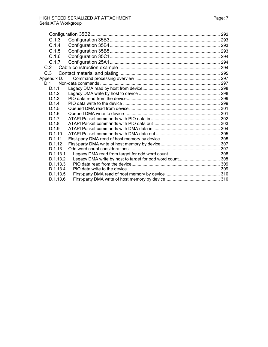
Page: 7
Appendix D.
Configuration 35B2........................................................................................................... 292
C.1.3 Configuration 35B3........................................................................................... 293
C.1.4 Configuration 35B4........................................................................................... 293
C.1.5 Configuration 35B5........................................................................................... 293
C.1.6 Configuration 35C1........................................................................................... 294
C.1.7 Configuration 25A1........................................................................................... 294
C.2 Cable construction example.................................................................................... 294
C.3 Contact material and plating ................................................................................... 295
Command processing overview ...................................................................... 297
D.1 Non-data commands ................................................................................................... 297
Legacy DMA read by host from device................................................................ 298
D.1.1
Legacy DMA write by host to device ................................................................... 298
D.1.2
PIO data read from the device............................................................................. 299
D.1.3
PIO data write to the device ................................................................................ 299
D.1.4
Queued DMA read from device ........................................................................... 301
D.1.5
Queued DMA write to device............................................................................... 301
D.1.6
ATAPI Packet commands with PIO data in ......................................................... 302
D.1.7
ATAPI Packet commands with PIO data out....................................................... 303
D.1.8
D.1.9
ATAPI Packet commands with DMA data in ....................................................... 304
D.1.10 ATAPI Packet commands with DMA data out ..................................................... 305
D.1.11 First-party DMA read of host memory by device ................................................. 305
D.1.12 First-party DMA write of host memory by device................................................. 307
D.1.13 Odd word count considerations ........................................................................... 307
Legacy DMA read from target for odd word count .......................................... 308
D.1.13.1
D.1.13.2
Legacy DMA write by host to target for odd word count.................................. 308
D.1.13.3
PIO data read from the device......................................................................... 309
D.1.13.4
PIO data write to the device............................................................................. 309
First-party DMA read of host memory by device ............................................. 310
D.1.13.5
D.1.13.6
First-party DMA write of host memory by device............................................. 310
�



 2023年江西萍乡中考道德与法治真题及答案.doc
 2012年重庆南川中考生物真题及答案.doc
 2013年江西师范大学地理学综合及文艺理论基础考研真题.doc
 2020年四川甘孜小升初语文真题及答案I卷.doc
 2020年注册岩土工程师专业基础考试真题及答案.doc
 2023-2024学年福建省厦门市九年级上学期数学月考试题及答案.doc
 2021-2022学年辽宁省沈阳市大东区九年级上学期语文期末试题及答案.doc
 2022-2023学年北京东城区初三第一学期物理期末试卷及答案.doc
 2018上半年江西教师资格初中地理学科知识与教学能力真题及答案.doc
 2012年河北国家公务员申论考试真题及答案-省级.doc
 2020-2021学年江苏省扬州市江都区邵樊片九年级上学期数学第一次质量检测试题及答案.doc
 2022下半年黑龙江教师资格证中学综合素质真题及答案.doc