RTL8139D
RTL8139DL
RTL8139D-LF
RTL8139DL-LF
RTL8139D-GR
RTL8139DL-GR
SINGLE-CHIP MULTI-FUNCTION 10/100Mbps
ETHERNET CONTROLLER WITH POWER
MANAGEMENT
DATASHEET
Rev. 1.2
08 Aug 2005
Track ID: JATR-1076-21
�
RTL8139DL
Datasheet
COPYRIGHT
©2005 Realtek Semiconductor Corp. All rights reserved. No part of this document may be reproduced,
transmitted, transcribed, stored in a retrieval system, or translated into any language in any form or by any
means without the written permission of Realtek Semiconductor Corp.
DISCLAIMER
Realtek provides this document “as is”, without warranty of any kind, neither expressed nor implied,
including, but not limited to, the particular purpose. Realtek may make improvements and/or changes in
this document or in the product described in this document at any time. This document could include
technical inaccuracies or typographical errors.
TRADEMARKS
Realtek is a trademark of Realtek Semiconductor Corporation. Other names mentioned in this document are
trademarks/registered trademarks of their respective owners.
USING THIS DOCUMENT
Though every effort has been made to ensure that this document is current and accurate, more information
may have become available subsequent to the production of this guide. In that event, please contact your
Realtek representative for additional information that may help in the development process.
REVISION HISTORY
Revision
1.2
Release Date
2005/08/08
Summary
Added section 13 Ordering Information, on page 61.
Added lead (Pb)-free and version package identification information on
page 2 and page 3.
Single Chip Multifunction 10/100 Ethernet Controller w/Power Management
ii
Track ID: JATR-1076-21 Rev. 1.2
�
Table of Contents
RTL8139DL
Datasheet
1. GENERAL DESCRIPTION...............................................................................................................1
2. FEATURES ..........................................................................................................................................2
3.1.
3.2.
4.1.
4.2.
4.3.
4.4.
4.5.
4.6.
4.7.
4.8.
3. PIN ASSIGNMENTS ..........................................................................................................................2
PACKAGE IDENTIFICATION......................................................................................................2
PACKAGE IDENTIFICATION......................................................................................................3
4. PIN DESCRIPTIONS .........................................................................................................................4
POWER MANAGEMENT/ISOLATION INTERFACE.......................................................................4
PCI INTERFACE.......................................................................................................................4
EEPROM INTERFACE.............................................................................................................6
POWER PINS............................................................................................................................6
LED INTERFACE .....................................................................................................................6
ATTACHMENT UNIT INTERFACE..............................................................................................7
MULTI-FUNCTION INTERFACE ................................................................................................7
TEST AND OTHER PINS...........................................................................................................7
5. REGISTER DESCRIPTIONS............................................................................................................8
RECEIVE STATUS REGISTER IN RX PACKET HEADER ............................................................10
TRANSMIT STATUS REGISTER...............................................................................................11
ERSR: EARLY RX STATUS REGISTER...................................................................................12
COMMAND REGISTER ...........................................................................................................12
INTERRUPT MASK REGISTER ................................................................................................13
INTERRUPT STATUS REGISTER..............................................................................................13
TRANSMIT CONFIGURATION REGISTER.................................................................................14
RECEIVE CONFIGURATION REGISTER....................................................................................15
9346CR: 93C46 COMMAND REGISTER.................................................................................18
CONFIG 0: CONFIGURATION REGISTER 0............................................................................19
CONFIG 1: CONFIGURATION REGISTER 1............................................................................20
MEDIA STATUS REGISTER.....................................................................................................21
CONFIG 3: CONFIGURATION REGISTER3.............................................................................22
CONFIG 4: CONFIGURATION REGISTER4.............................................................................23
MULTIPLE INTERRUPT SELECT REGISTER .............................................................................24
PCI REVISION ID..................................................................................................................24
TRANSMIT STATUS OF ALL DESCRIPTORS (TSAD) REGISTER ..............................................24
BASIC MODE CONTROL REGISTER........................................................................................25
BASIC MODE STATUS REGISTER...........................................................................................26
AUTO-NEGOTIATION ADVERTISEMENT REGISTER.................................................................26
AUTO-NEGOTIATION LINK PARTNER ABILITY REGISTER .....................................................27
AUTO-NEGOTIATION EXPANSION REGISTER .........................................................................28
DISCONNECT COUNTER ........................................................................................................28
5.1.
5.2.
5.3.
5.4.
5.5.
5.6.
5.7.
5.8.
5.9.
5.10.
5.11.
5.12.
5.13.
5.14.
5.15.
5.16.
5.17.
5.18.
5.19.
5.20.
5.21.
5.22.
5.23.
Single Chip Multifunction 10/100 Ethernet Controller w/Power Management
iii
Track ID: JATR-1076-21 Rev. 1.2
�
RTL8139DL
Datasheet
6.1.
6.2.
5.24.
5.25.
5.26.
5.27.
5.28.
FALSE CARRIER SENSE COUNTER.........................................................................................28
NWAY TEST REGISTER.........................................................................................................29
RX_ER COUNTER ................................................................................................................29
CS CONFIGURATION REGISTER.............................................................................................29
CONFIG5: CONFIGURATION REGISTER 5 ...............................................................................30
6. EEPROM (93C46) CONTENTS ......................................................................................................31
SUMMARY OF RTL8139D(L) EEPROM REGISTERS ............................................................33
SUMMARY OF EEPROM POWER MANAGEMENT REGISTERS................................................33
7. PCI CONFIGURATION SPACE REGISTERS.............................................................................34
PCI CONFIGURATION SPACE TABLE .....................................................................................34
PCI CONFIGURATION SPACE FUNCTIONS..............................................................................36
DEFAULT VALUES AFTER POWER-ON (RSTB ASSERTED) ....................................................40
PCI POWER MANAGEMENT FUNCTIONS ...............................................................................41
8. BLOCK DIAGRAM..........................................................................................................................45
7.1.
7.2.
7.3.
7.4.
9.1.
9.2.
9.3.
9.4.
9.5.
9.6.
9.7.
9.8.
9.9.
9.10.
9. FUNCTIONAL DESCRIPTION......................................................................................................46
TRANSMIT OPERATION .........................................................................................................46
RECEIVE OPERATION ............................................................................................................46
BASE LINE WANDER COMPENSATION...................................................................................46
LINE QUALITY MONITOR......................................................................................................46
CLOCK RECOVERY MODULE.................................................................................................47
LOOPBACK OPERATION ........................................................................................................47
TX ENCAPSULATION .............................................................................................................47
COLLISION ............................................................................................................................47
RX DECAPSULATION.............................................................................................................48
FLOW CONTROL....................................................................................................................48
9.10.1. Control Frame Transmission...............................................................................................48
9.10.2. Control Frame Reception ....................................................................................................48
LED FUNCTIONS...................................................................................................................49
10/100Mbps Link Monitor ...................................................................................................49
9.11.1.
9.11.2. LED_RX...............................................................................................................................49
9.11.3. LED_TX ...............................................................................................................................50
9.11.4. LED_TX+LED_RX..............................................................................................................50
APPLICATION DIAGRAM ............................................................................................51
9.11.
10.
11.
11.3.
11.1.
11.2.
ELECTRICAL CHARACTERISTICS ...........................................................................52
TEMPERATURE LIMIT RATINGS.............................................................................................52
DC CHARACTERISTICS..........................................................................................................52
Supply Voltage Vcc = 3.0V min. to 3.6V max......................................................................52
Supply Voltage Vdd25 = 2.3V min. to 2.7V max. ................................................................52
AC CHARACTERISTICS..........................................................................................................53
11.3.1. PCI Bus Operation Timing ..................................................................................................53
11.2.1.
11.2.2.
Single Chip Multifunction 10/100 Ethernet Controller w/Power Management
iv
Track ID: JATR-1076-21 Rev. 1.2
�
RTL8139DL
Datasheet
MECHANICAL DIMENSIONS ......................................................................................59
QFP......................................................................................................................................59
LQFP....................................................................................................................................60
ORDERING INFORMATION.........................................................................................61
12.
12.1.
12.2.
13.
Single Chip Multifunction 10/100 Ethernet Controller w/Power Management
v
Track ID: JATR-1076-21 Rev. 1.2
�
RTL8139DL
Datasheet
1. General Description
The Realtek RTL8139D(L) is a highly integrated and cost-effective single-chip Fast Ethernet controller
that provides 32-bit performance, PCI bus master capability, and full compliance with IEEE 802.3u
100Base-T specifications and IEEE 802.3x Full Duplex Flow Control. It also supports Advanced
Configuration Power management Interface (ACPI), PCI power management for modern operating
systems that are capable of Operating System Directed Power Management (OSPM) to achieve the most
efficient power management possible. The RTL8139D(L) also supports shared Boot ROM pins & clock run
pin.
In addition to the ACPI feature, the RTL8139D(L) also supports remote wake-up (including AMD Magic
Packet, LinkChg, and Microsoft® wake-up frame) in both ACPI and APM environments. The
RTL8139D(L) is capable of performing an internal reset through the application of auxiliary power. When
auxiliary power is applied and the main power remains off, the RTL8139D(L) is ready and is waiting for
the Magic Packet or Link Change to wake the system up. Also, the LWAKE pin provides 4 different output
signals including active high, active low, positive pulse, and negative pulse. The versatility of the
RTL8139D(L) LWAKE pin provides motherboards with Wake-On-LAN (WOL) functionality.
The RTL8139D(L) also supports Analog Auto-Power-down, that is, the analog part of the RTL8139D(L)
can be shut down temporarily according to user requirement or when the RTL8139D(L) is in a power down
state with the wakeup function disabled. In addition, when the analog part is shut down and the IsolateB pin
is low (i.e. the main power is off), then both the analog and digital parts stop functioning and the power
consumption of the RTL8139D(L) will be negligible. The RTL8139D(L) also supports an auxiliary power
auto-detect function, and will auto-configure related bits of their own PCI power management registers in
PCI configuration space.
PCI Vital Product Data (VPD) is also supported to provide the information that uniquely identifies
hardware (Ex., the OEM brand name of RTL8139D(L) LAN card). The information may consist of part
number, serial number, and other detailed information.
To provide cost down support, the RTL8139D(L) is capable of using a 25MHz crystal or OSC as its internal
clock source.
The RTL8139D(L) keeps network maintenance costs low and eliminates usage barriers. It is the easiest
way to upgrade a network from 10 to 100Mbps. It also supports full-duplex operation, making 200Mbps
bandwidth possible at no additional cost. To improve compatibility with other brands’ products, the
RTL8139D(L) is also capable of receiving packets with InterFrameGap no less than 40 Bit-Time. The
RTL8139D(L) is highly integrated and requires no “glue” logic or external memory.
The RTL8139D(L) provides a flexible multi-function mode (Realtek patent pending) to incorporate other
PCI master devices, like a hardware modem. When in multi-function mode, the RTL8139D(L) acts as an
arbiter to distinguish LAN signals from those of other devices. The second device recognizes no difference
between being connected to the RTL8139D or a regular PCI bus.
The RTL8139D(L) includes a PCI and Expansion Memory Share Interface (Realtek’s patent pending) for a
boot ROM and can be used in diskless workstations, providing maximum network security and ease of
management.
Single Chip Multifunction 10/100 Ethernet Controller w/Power Management
1
Track ID: JATR-1076-21 Rev. 1.2
�
2. Features
100 pin QFP/LQFP
Integrated Fast Ethernet MAC, Physical chip
and transceiver in one chip
10Mbps and 100Mbps operation
Supports 10Mbps and 100Mbps N-way
Auto-negotiation operation
Supports PCI multi-function capabilities
PCI local bus single-chip Fast Ethernet
controller
Complies with PCI Revision 2.2
Supports PCI clock 16.75MHz-40MHz
Supports PCI target fast back-to-back
transaction
Provides PCI bus master data transfers
and PCI memory space or I/O space
mapped data transfers of
RTL8139D(L)'s operational registers
Supports PCI VPD (Vital Product
Data)
Supports ACPI, PCI power
management
Supports PCI multi-function to
incorporate with other PCI master
device
Supports 25MHz crystal or 25MHz
OSC as the internal clock source. The
frequency deviation of either crystal or
OSC must be within 50 PPM.
Complies with PC99 and PC2001 standards
Supports Wake-On-LAN function and remote
wake-up (Magic Packet*, LinkChg and
Microsoft® wake-up frame)
RTL8139DL
Datasheet
Supports 4 Wake-On-LAN (WOL) signals
(active high, active low, positive pulse, and
negative pulse)
Supports auxiliary power-on internal reset, to
be ready for remote wake-up when main
power remains off
Supports auxiliary power auto-detect, and sets
the related capability of power management
registers in PCI configuration space
Includes a programmable, PCI burst size and
early Tx/Rx threshold
Supports a 32-bit general-purpose timer with
the external PCI clock as clock source, to
generate timer-interrupt
Contains two large (2Kbyte) independent
receive and transmit FIFO’s
Advanced power saving mode when LAN
function or wakeup function is not used
Uses 93C46 (64*16-bit EEPROM) to store
resource configuration, ID parameter, and
VPD data
Supports LED pins for various network
activity indications
Supports loopback capability
Half/Full duplex capability
Supports Full Duplex Flow Control (IEEE
802.3x)
2.5/3.3V power supply with 5V tolerant I/Os
Up to 128K byte Boot ROM interface for both
EPROM and Flash memory is supported
0.25u CMOS process
Single Chip Multifunction 10/100 Ethernet Controller w/Power Management
2
Track ID: JATR-1076-21 Rev. 1.2
�
3. Pin Assignments
66 GND
67 RXIN-
68 RXIN+
69 NC
70 AVDD
71 TXD-
72 TXD+
73 GND
74 ISOLATEB
75 AVDD
76 NC
77 LED2
78 IDSEL2
79 LED1
80 LED0
81 INTAB
82 RSTB
83 CLK
84 GNTB
85 REQB
86 AD31
87 AD30
88 GND
89 AD29
90 VDD
91 AD28
92 AD27
93 AD26
94 AD25
95 AD24
96 VDD25
97 VDD
98 CBE3B
99 IDSEL
100 AD23
1 AD22
2 GND
3 AD21
4 AD20
5 AD19
6 VDD
7 NC
8 AD18
9 AD17
10 AD16
11 CBE2B
12 FRAMEB
13 IRDYB
14 TRDYB
15 DEVSELB
RTL8139D QFP
LLLLLLL
TXXXX TAIWAN
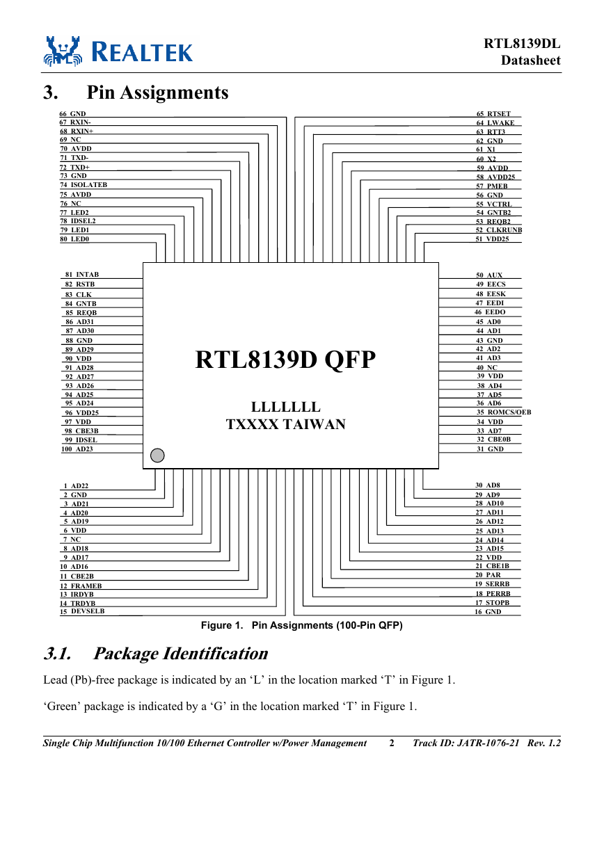
Figure 1. Pin Assignments (100-Pin QFP)
3.1. Package Identification
Lead (Pb)-free package is indicated by an ‘L’ in the location marked ‘T’ in Figure 1.
‘Green’ package is indicated by a ‘G’ in the location marked ‘T’ in Figure 1.
RTL8139DL
Datasheet
65 RTSET
64 LWAKE
63 RTT3
62 GND
61 X1
60 X2
59 AVDD
58 AVDD25
57 PMEB
56 GND
55 VCTRL
54 GNTB2
53 REQB2
52 CLKRUNB
51 VDD25
50 AUX
49 EECS
48 EESK
47 EEDI
46 EEDO
45 AD0
44 AD1
43 GND
42 AD2
41 AD3
40 NC
39 VDD
38 AD4
37 AD5
36 AD6
35 ROMCS/OEB
34 VDD
33 AD7
32 CBE0B
31 GND
30 AD8
29 AD9
28 AD10
27 AD11
26 AD12
25 AD13
24 AD14
23 AD15
22 VDD
21 CBE1B
20 PAR
19 SERRB
18 PERRB
17 STOPB
16 GND
Single Chip Multifunction 10/100 Ethernet Controller w/Power Management
2
Track ID: JATR-1076-21 Rev. 1.2
�



 2023年江西萍乡中考道德与法治真题及答案.doc
 2012年重庆南川中考生物真题及答案.doc
 2013年江西师范大学地理学综合及文艺理论基础考研真题.doc
 2020年四川甘孜小升初语文真题及答案I卷.doc
 2020年注册岩土工程师专业基础考试真题及答案.doc
 2023-2024学年福建省厦门市九年级上学期数学月考试题及答案.doc
 2021-2022学年辽宁省沈阳市大东区九年级上学期语文期末试题及答案.doc
 2022-2023学年北京东城区初三第一学期物理期末试卷及答案.doc
 2018上半年江西教师资格初中地理学科知识与教学能力真题及答案.doc
 2012年河北国家公务员申论考试真题及答案-省级.doc
 2020-2021学年江苏省扬州市江都区邵樊片九年级上学期数学第一次质量检测试题及答案.doc
 2022下半年黑龙江教师资格证中学综合素质真题及答案.doc