Copyright
Preface
This publication, including all photographs, illustrations and software, is protected un-
der international copyright laws, with all rights reserved. Neither this manual, nor any
of the material contained herein, may be reproduced without w ritten consent of the au-
thor.
Version 2.0
Disclaimer
The information in this document is subject to change without notice. The manufac-
turer makes no representations or warranties with respect to the contents hereof and
specifically disclaim any implied warranties of merchantability or fitness for any par-
ticular purpose. The manufacturer reserves the right to revise this publication and to
make changes from time to time in the content hereof without obligation of the manu-
facturer to notify any person of such revision or changes.
Trademark Recognition
Microsoft, MS-DOS and Windows are registered trademarks of Microsoft Corp.
MMX, Pentium, Pentium-II, Pentium-III, Celeron are registered trademarks of Intel
Corporation.
Other product names used in this manual are the properties of their respective owners
and are acknowledged.
Federal Communications Commission (FCC)
This equipment has been tested and found to comply with the limits for a Class B digi-
tal device, pursuant to Part 15 of the FCC Rules. These limits are designed to provide
reasonable protection against harmful interference in a residential installation. This
equipment generates, uses, and can radiate radio frequency energy and, if not in-
stalled and used in accordance with the instructions, may cause harmful interference
to radio communications. However, there is no guarantee that interference will not oc-
cur in a particular installation. If this equipment does cause harmful interference to
radio or television reception, which can be determined by turning the equipment off
and on, the user is encouraged to try to correct the interference by one or more of the
following measures:
Reorient or relocate the receiving antenna.
Connect the equipment onto an outlet on a circuit different from that to which
Increase the separation between the equipment and the receiver.
the receiver is connected.
Consult the dealer or an experienced radio/TV technician for help.
Shielded interconnect cables and a shielded AC power cable must be employed with
this equipment to ensure compliance with the pertinent RF emission limits governing
this device. Changes or modifications not expressly approved by the system's manu-
facturer could void the user's authority to operate the equipment.
-
-
-
-
�
Declaration of Conformity
This device complies with part 15 of the FCC rules. Operation is subject to the follow-
ing conditions:
This device may not cause harmful interference, and
This device must accept any interference received, including interference
that may cause undesired operation.
Canadian Department of Communications
This class B digital apparatus meets all requirements of the Canadian Interference-
causing Equipment Regulations.
Cet appareil numérique de la classe B respecte toutes les exigences du Réglement
sur le matériel brouilieur du Canada.
page 1
page 6
Describes features of the mainboard,
and provides a shipping checklist.
Go to
Describes installation of mainboard
components.
Go to
Provides information on using the BIOS
Setup Utility.
Go to
Describes the mainboard software.
Go to
page 24
page 50
About the Manual
The manual consists of the following:
Chapter 1
Introducing the Mainboard
Chapter 2
Installing the Mainboard
Chapter 3
Using BIOS
Chapter 4
Using the Mainboard Software
ii
-
-
�
TTAABBLLEE OOFF CCOONNTTEENNTTSS
Preface
Features and Packing List Translations
~
! |wqC
i
CHAPTER 1
Introducing the Mainboard
1
1
Introduction............................................................................................................1
Checklist.................................................................................................................1
Standard Items ................................................................................................... 1
Features..................................................................................................................2
Choosing a Computer Case................................................................................3
Mainboard Components.......................................................................................4
CHAPTER 2
Installing the Mainboard
6
6
Safety Precautions................................................................................................6
Quick Guide...........................................................................................................6
Installing the Mainboard in a Case.....................................................................7
Checking Jumper Settings...................................................................................7
Setting Jumpers ................................................................................................. 7
Checking Jumper Settings................................................................................. 8
Jumper Settings ................................................................................................. 8
Connecting Case Components...........................................................................9
The Panel Connectors...................................................................................... 10
Installing Hardware.............................................................................................11
Installing the Processor................................................................................... 11
Installing Memory Modules ............................................................................ 14
Installing a Hard Disk Drive/CD-ROM .......................................................... 15
Installing a Hard Disk Drive........................................................................... 15
Installing a CD-ROM/DVD Drive .................................................................. 16
Installing a Floppy Diskette Drive .................................................................. 16
Installing Add-on Cards .................................................................................. 17
Connecting Optional Devices.......................................................................... 18
Connecting I/O Devices.....................................................................................22
External Connector Color Coding................................................................... 23
CHAPTER 3
Using BIOS
24
24
About the Setup Utility........................................................................................24
The Standard Configuration............................................................................ 24
Entering the Setup Utility................................................................................ 25
Updating the BIOS.......................................................................................... 25
iii
�
Using BIOS ..........................................................................................................26
Standard CMOS Features................................................................................ 27
Advanced BIOS Setup Option ........................................................................ 29
Advanced Chipset Features Option................................................................. 31
Integrated Peripherals Option.......................................................................... 36
Power Management Setup Option................................................................... 40
PNP/PCI Configuration Option....................................................................... 44
PC Health Status Option.................................................................................. 46
Frequency/Voltage Control.............................................................................. 46
Load Fail-Safe Defaults Option ...................................................................... 48
Load Optimized Defaults Option .................................................................... 48
Set Password Option ....................................................................................... 48
Save & Exit Setup Option ............................................................................... 49
Exit Without Saving ........................................................................................ 49
CHAPTER 4
Using the Mainboard Software
50
50
About the Software CD-ROM............................................................................50
Auto-installing under Windows 98....................................................................50
Running Setup................................................................................................. 51
Manual Installation..............................................................................................53
Utility Software Reference.................................................................................53
iv
�
CChhaapptteerr 11
Introducing the Mainboard
IInnttrroodduuccttiioonn
Congratulations on purchasing the P4VXMD mainboard. The P4VXMD main-
board is a Micro ATX mainboard that uses a 4-layer printed circuit board and
measures 244 mm x 244 mm. The mainboard features a Socket 478 that ac-
commodates Intel Pentium 4 processors supporting front side bus (FSB)
speeds up to 533MHz.
The P4VXMD incorporates the VIA VT8753A (P4X266A) Northbridge and
VT8233A Southbridge chipsets which supports the AC 97 audio codec, which
combines support for DDR (Double Data Rate) SDRAM up to 3 GB.
Note: SDRAM provides 800 MBps or 1 GBp s data transfer depending on
whether the bus is 100MHz or 133MHz. Double Data Rate SDRAM
(DDR SDRAM) doubles the rate to 1.6 GBps and 2.1 GBps. DDR
SDRAM uses additional power and ground lines and requires 184-pin
DIMM modules rather than the 168-pin DIMMs used by SDRAM.
CChheecckklliisstt
Compare the mainboard’s package contents with the following checklist:
Standard Items
• One mainboard
• One diskette drive ribbon cable
• One IDE drive ribbon cable
• One retention module
• Software support CD
•
This user’s manual
�
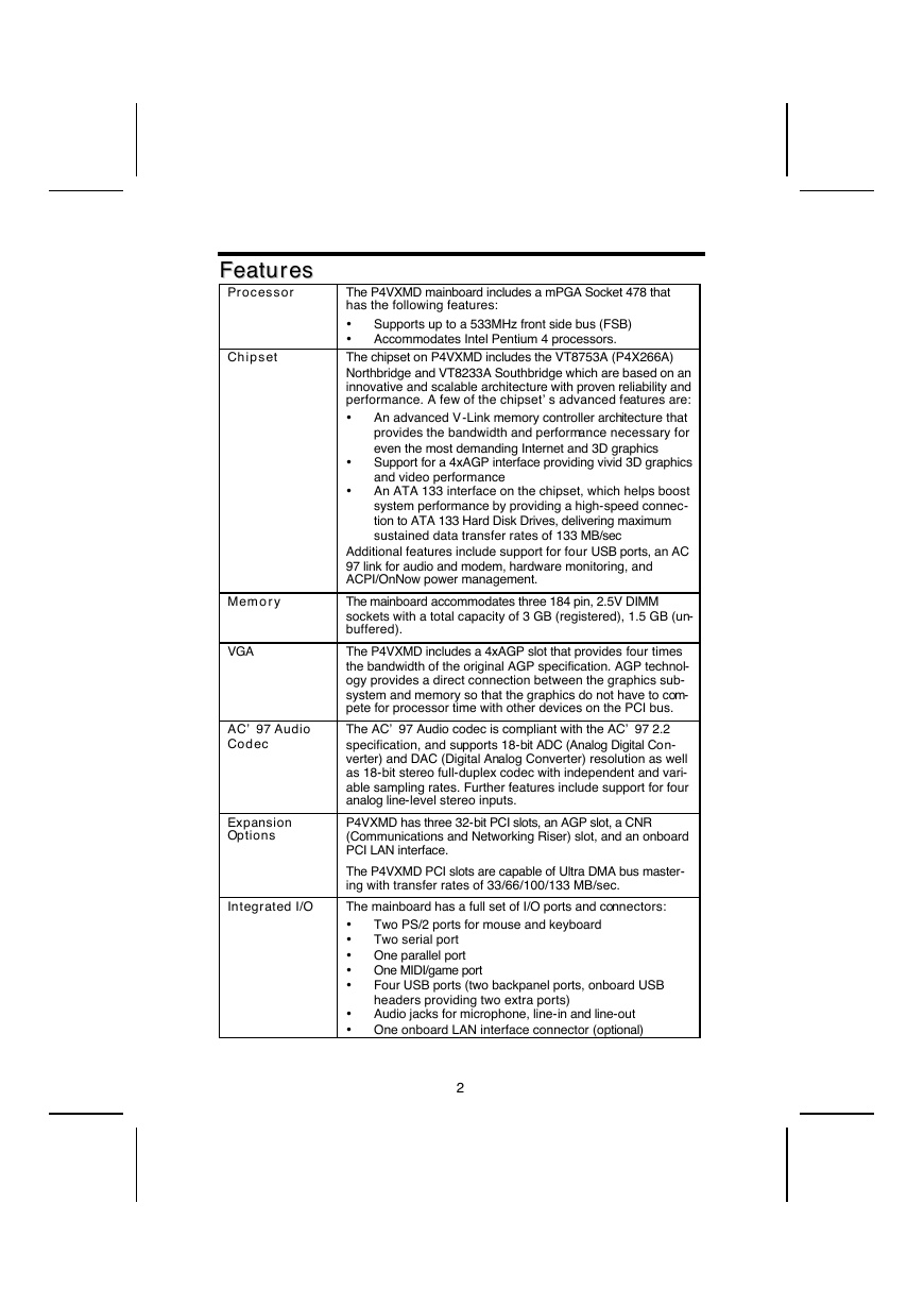
FFeeaattuurreess
Processor
Chipset
Memory
VGA
AC’ 97 Audio
Codec
Expansion
Options
Integrated I/O
Supports up to a 533MHz front side bus (FSB)
Accommodates Intel Pentium 4 processors.
The P4VXMD mainboard includes a mPGA Socket 478 that
has the following features:
•
•
The chipset on P4VXMD includes the VT8753A (P4X266A)
Northbridge and VT8233A Southbridge which are based on an
innovative and scalable architecture with proven reliability and
performance. A few of the chipset’s advanced features are:
•
An advanced V-Link memory controller architecture that
provides the bandwidth and performance necessary for
even the most demanding Internet and 3D graphics
Support for a 4xAGP interface providing vivid 3D graphics
and video performance
An ATA 133 interface on the chipset, which helps boost
system performance by providing a high-speed connec-
tion to ATA 133 Hard Disk Drives, delivering maximum
sustained data transfer rates of 133 MB/sec
•
•
Additional features include support for four USB ports, an AC
97 link for audio and modem, hardware monitoring, and
ACPI/OnNow power management.
The mainboard accommodates three 184 pin, 2.5V DIMM
sockets with a total capacity of 3 GB (registered), 1.5 GB (un-
buffered).
The P4VXMD includes a 4xAGP slot that provides four times
the bandwidth of the original AGP specification. AGP technol-
ogy provides a direct connection between the graphics sub-
system and memory so that the graphics do not have to com-
pete for processor time with other devices on the PCI bus.
The AC’ 97 Audio codec is compliant with the AC’ 97 2.2
specification, and supports 18-bit ADC (Analog Digital Con-
verter) and DAC (Digital Analog Converter) resolution as well
as 18-bit stereo full-duplex codec with independent and vari-
able sampling rates. Further features include support for four
analog line-level stereo inputs.
P4VXMD has three 32-bit PCI slots, an AGP slot, a CNR
(Communications and Networking Riser) slot, and an onboard
PCI LAN interface.
The P4VXMD PCI slots are capable of Ultra DMA bus master-
ing with transfer rates of 33/66/100/133 MB/sec.
The mainboard has a full set of I/O ports and connectors:
•
Two PS/2 ports for mouse and keyboard
•
Two serial port
• One parallel port
• One MIDI/game port
•
Four USB ports (two backpanel ports, onboard USB
headers providing two extra ports)
•
Audio jacks for microphone, line-in and line-out
• One onboard LAN interface connector (optional)
2
�
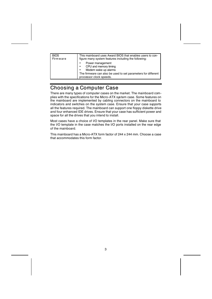
BIOS
Firmware
This mainboard uses Award BIOS that enables users to con-
figure many system features including the following:
•
Power management
•
CPU and memory timing
• Modem wake up alarms
The firmware can also be used to set parameters for different
processor clock speeds.
CChhoooossiinngg aa CCoommppuutteerr CCaassee
There are many types of computer cases on the market. The mainboard com-
plies with the specifications for the Micro-ATX system case. Some features on
the mainboard are implemented by cabling connectors on the mainboard to
indicators and switches on the system case. Ensure that your case supports
all the features required. The mainboard can support one floppy diskette drive
and four enhanced IDE drives. Ensure that your case has sufficient power and
space for all the drives that you intend to install.
Most cases have a choice of I/O templates in the rear panel. Make sure that
the I/O template in the case matches the I/O ports installed on the rear edge
of the mainboard.
This mainboard has a Micro-ATX form factor of 244 x 244 mm. Choose a case
that accommodates this form factor.
3
�
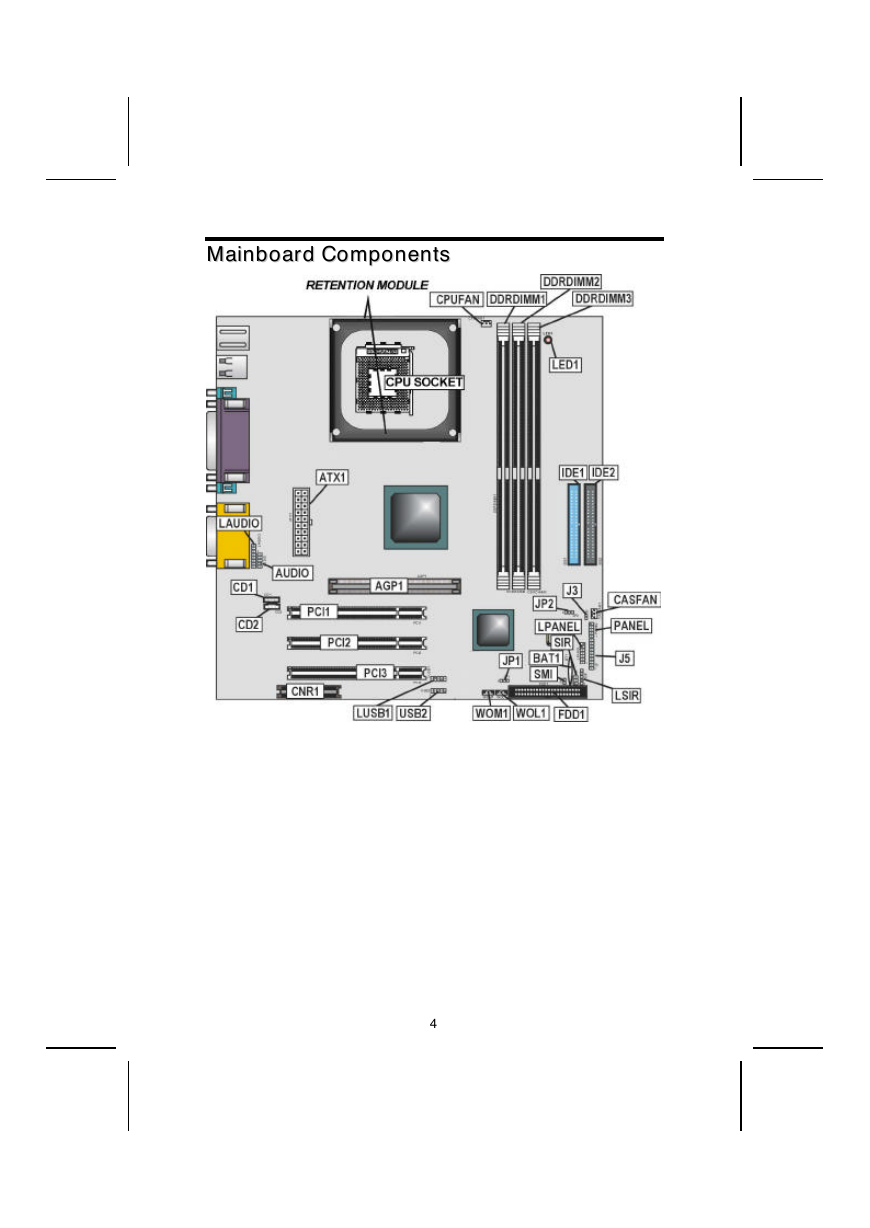
MMaaiinnbbooaarrdd CCoommppoonneennttss
4
�



 2023年江西萍乡中考道德与法治真题及答案.doc
 2012年重庆南川中考生物真题及答案.doc
 2013年江西师范大学地理学综合及文艺理论基础考研真题.doc
 2020年四川甘孜小升初语文真题及答案I卷.doc
 2020年注册岩土工程师专业基础考试真题及答案.doc
 2023-2024学年福建省厦门市九年级上学期数学月考试题及答案.doc
 2021-2022学年辽宁省沈阳市大东区九年级上学期语文期末试题及答案.doc
 2022-2023学年北京东城区初三第一学期物理期末试卷及答案.doc
 2018上半年江西教师资格初中地理学科知识与教学能力真题及答案.doc
 2012年河北国家公务员申论考试真题及答案-省级.doc
 2020-2021学年江苏省扬州市江都区邵樊片九年级上学期数学第一次质量检测试题及答案.doc
 2022下半年黑龙江教师资格证中学综合素质真题及答案.doc