ILI9486L
a-Si TFT LCD Single Chip Driver
320RGBx480 Resolution and 262K-color
Specification
Preliminary
Version: V0.06
Document No: ILI9486L_DS_V006.pdf
ILI TECHNOLOGY CORP.
8F, No. 38, Taiyuan St, Jhubei City,
Taiwan 302, R.O.C.
Tel.886-3-5600099; Fax.886-3-5600585
http://www.ilitek.com
�
a-Si TFT LCD Single Chip Driver
320RGBx480 Resolution and 262K-color
ILI9486L
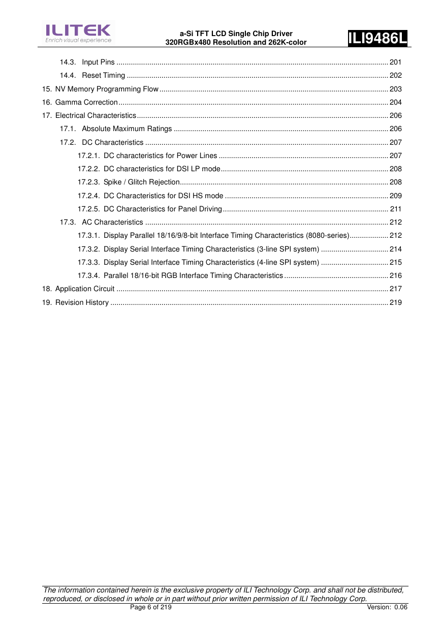
Table of Contents
Section Page
1.
Introduction .................................................................................................................................................... 7
2. Features ........................................................................................................................................................ 7
3. Block Diagram ............................................................................................................................................... 9
4. Pin Descriptions .......................................................................................................................................... 10
5. Pad Arrangement and Coordination ............................................................................................................ 14
6. Block Function Description .......................................................................................................................... 24
7. Function Description ................................................................................................................................... 26
7.1. MCU interfaces .............................................................................................................................. 26
7.1.1. MCU interface selection ...................................................................................................... 26
7.1.2. 8080-Series Parallel Interface ............................................................................................. 27
7.1.2.1. Write Cycle Sequence ......................................................................................................... 28
7.1.2.2. Read Cycle Sequence ......................................................................................................... 29
7.1.3. Serial Interface .................................................................................................................... 30
7.1.3.1. Write Cycle Sequence ......................................................................................................... 30
7.1.3.2. Read Cycle Sequence ......................................................................................................... 32
7.1.4. Data Transfer Break and Recovery ..................................................................................... 34
7.1.5. Data Transfer Pause ............................................................................................................ 36
7.1.5.1. Serial Interface Pause ......................................................................................................... 37
7.1.5.2. Parallel Interface Pause ...................................................................................................... 37
7.1.6. Data Transfer Mode ............................................................................................................. 38
7.1.6.1. Method 1 .............................................................................................................................. 38
7.1.6.2. Method 2 .............................................................................................................................. 38
7.2. RGB Interface ................................................................................................................................ 39
7.2.1. RGB Interface Selection ...................................................................................................... 39
7.2.2. RGB Interface Timing .......................................................................................................... 41
7.3. CABC (Content Adaptive Brightness Control)................................................................................ 42
7.4. Display Data RAM (DDRAM) ......................................................................................................... 44
7.5. Display Data Format ...................................................................................................................... 45
7.5.1. 3-line Serial Interface ........................................................................................................... 45
7.5.2. 4-line Serial Interface ........................................................................................................... 47
7.5.3. 8-bit Parallel MCU Interface ................................................................................................ 49
7.5.3.1. 8-bit Data Bus for 16-bit/pixel (RGB 5-6-5 bits input), 65K-color ........................................ 50
7.5.3.2. 8-bit Data Bus for 18-bit/pixel (RGB 6-6-6 bits input), 262K-color ...................................... 51
7.5.4. 9-bit Parallel MCU Interface ................................................................................................ 52
7.5.5. 16-bit Parallel MCU Interface .............................................................................................. 53
7.5.5.1. 16-bit Data Bus for 16-bit/pixel (RGB 5-6-5 bits input), 65K-color ...................................... 54
7.5.5.2. 16-bit Data Bus for 18-bit/pixel (RGB 6-6-6 bits input), 262K-color .................................... 55
The information contained herein is the exclusive property of ILI Technology Corp. and shall not be distributed,
reproduced, or disclosed in whole or in part without prior written permission of ILI Technology Corp.
Page 2 of 219
Version: 0.06
�
a-Si TFT LCD Single Chip Driver
320RGBx480 Resolution and 262K-color
ILI9486L
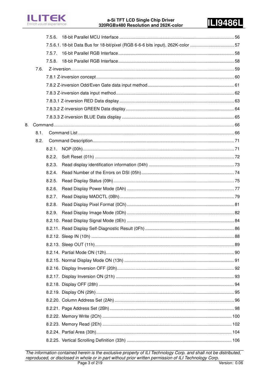
7.5.6. 18-bit Parallel MCU Interface .............................................................................................. 56
7.5.6.1. 18-bit Data Bus for 18-bit/pixel (RGB 6-6-6 bits input), 262K-color .................................... 57
7.5.7. 16-bit Parallel RGB Interface ............................................................................................... 58
7.5.8. 18-bit Parallel RGB Interface ............................................................................................... 58
7.6. Z-inversion...................................................................................................................................... 59
7.8.1 Z-inversion concept ................................................................................................................. 60
7.8.2 Z-inversion Odd/Even Gate data input method ....................................................................... 61
7.8.3 Z-inversion data input method ................................................................................................. 62
7.8.3.1 Z-inversion RED Data display .............................................................................................. 63
7.8.3.2 Z-inversion GREEN Data display ......................................................................................... 64
7.8.3.3 Z-inversion BLUE Data display ............................................................................................ 65
8. Command .................................................................................................................................................... 66
8.1. Command List ................................................................................................................................ 66
8.2. Command Description .................................................................................................................... 71
8.2.1. NOP (00h) ............................................................................................................................ 71
8.2.2. Soft Reset (01h) .................................................................................................................. 72
8.2.3. Read display identification information (04h) ...................................................................... 73
8.2.4. Read Number of the Errors on DSI (05h) ............................................................................ 74
8.2.5. Read Display Status (09h) ................................................................................................... 75
8.2.6. Read Display Power Mode (0Ah) ........................................................................................ 77
8.2.7. Read Display MADCTL (0Bh) .............................................................................................. 79
8.2.8. Read Display Pixel Format (0Ch) ........................................................................................ 81
8.2.9. Read Display Image Mode (0Dh) ........................................................................................ 82
8.2.10. Read Display Signal Mode (0Eh) ........................................................................................ 84
8.2.11. Read Display Self-Diagnostic Result (0Fh) ......................................................................... 86
8.2.12. Sleep IN (10h) ..................................................................................................................... 88
8.2.13. Sleep OUT (11h) .................................................................................................................. 89
8.2.14. Partial Mode ON (12h) ......................................................................................................... 90
8.2.15. Normal Display Mode ON (13h) .......................................................................................... 91
8.2.16. Display Inversion OFF (20h)................................................................................................ 92
8.2.17. Display Inversion ON (21h) ................................................................................................. 93
8.2.18. Display OFF (28h) ............................................................................................................... 94
8.2.19. Display ON (29h) ................................................................................................................. 95
8.2.20. Column Address Set (2Ah) .................................................................................................. 96
8.2.21. Page Address Set (2Bh) ...................................................................................................... 98
8.2.22. Memory Write (2Ch) .......................................................................................................... 100
8.2.23. Memory Read (2Eh) .......................................................................................................... 102
8.2.24. Partial Area (30h) ............................................................................................................... 104
8.2.25. Vertical Scrolling Definition (33h) ...................................................................................... 106
The information contained herein is the exclusive property of ILI Technology Corp. and shall not be distributed,
reproduced, or disclosed in whole or in part without prior written permission of ILI Technology Corp.
Page 3 of 219
Version: 0.06
�
a-Si TFT LCD Single Chip Driver
320RGBx480 Resolution and 262K-color
ILI9486L
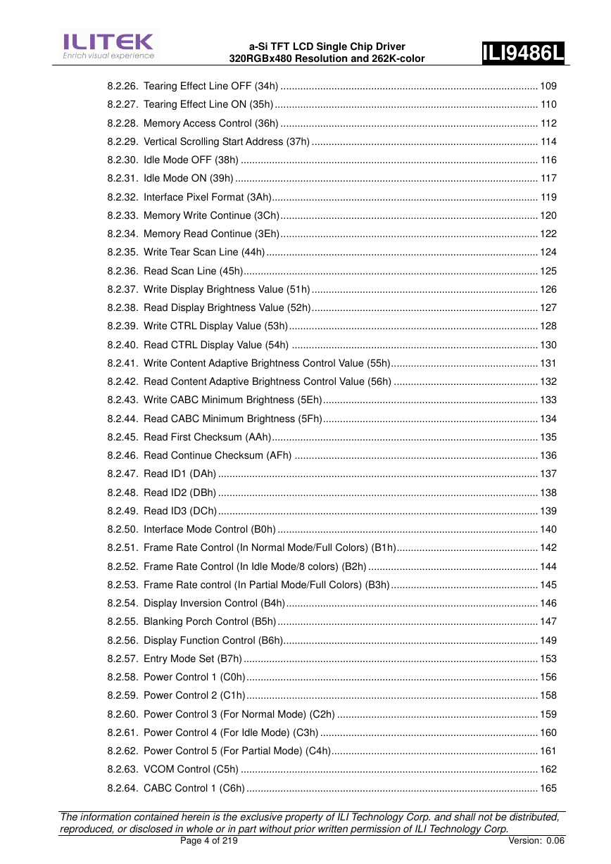
8.2.26. Tearing Effect Line OFF (34h) ........................................................................................... 109
8.2.27. Tearing Effect Line ON (35h) ............................................................................................. 110
8.2.28. Memory Access Control (36h) ........................................................................................... 112
8.2.29. Vertical Scrolling Start Address (37h) ................................................................................ 114
8.2.30. Idle Mode OFF (38h) ......................................................................................................... 116
8.2.31. Idle Mode ON (39h) ........................................................................................................... 117
8.2.32. Interface Pixel Format (3Ah).............................................................................................. 119
8.2.33. Memory Write Continue (3Ch) ........................................................................................... 120
8.2.34. Memory Read Continue (3Eh) ........................................................................................... 122
8.2.35. Write Tear Scan Line (44h) ................................................................................................ 124
8.2.36. Read Scan Line (45h) ........................................................................................................ 125
8.2.37. Write Display Brightness Value (51h) ................................................................................ 126
8.2.38. Read Display Brightness Value (52h) ................................................................................ 127
8.2.39. Write CTRL Display Value (53h) ........................................................................................ 128
8.2.40. Read CTRL Display Value (54h) ....................................................................................... 130
8.2.41. Write Content Adaptive Brightness Control Value (55h) .................................................... 131
8.2.42. Read Content Adaptive Brightness Control Value (56h) ................................................... 132
8.2.43. Write CABC Minimum Brightness (5Eh) ............................................................................ 133
8.2.44. Read CABC Minimum Brightness (5Fh) ............................................................................ 134
8.2.45. Read First Checksum (AAh) .............................................................................................. 135
8.2.46. Read Continue Checksum (AFh) ...................................................................................... 136
8.2.47. Read ID1 (DAh) ................................................................................................................. 137
8.2.48. Read ID2 (DBh) ................................................................................................................. 138
8.2.49. Read ID3 (DCh) ................................................................................................................. 139
8.2.50. Interface Mode Control (B0h) ............................................................................................ 140
8.2.51. Frame Rate Control (In Normal Mode/Full Colors) (B1h) .................................................. 142
8.2.52. Frame Rate Control (In Idle Mode/8 colors) (B2h) ............................................................ 144
8.2.53. Frame Rate control (In Partial Mode/Full Colors) (B3h) .................................................... 145
8.2.54. Display Inversion Control (B4h) ......................................................................................... 146
8.2.55. Blanking Porch Control (B5h) ............................................................................................ 147
8.2.56. Display Function Control (B6h).......................................................................................... 149
8.2.57. Entry Mode Set (B7h) ........................................................................................................ 153
8.2.58. Power Control 1 (C0h) ....................................................................................................... 156
8.2.59. Power Control 2 (C1h) ....................................................................................................... 158
8.2.60. Power Control 3 (For Normal Mode) (C2h) ....................................................................... 159
8.2.61. Power Control 4 (For Idle Mode) (C3h) ............................................................................. 160
8.2.62. Power Control 5 (For Partial Mode) (C4h) ......................................................................... 161
8.2.63. VCOM Control (C5h) ......................................................................................................... 162
8.2.64. CABC Control 1 (C6h) ....................................................................................................... 165
The information contained herein is the exclusive property of ILI Technology Corp. and shall not be distributed,
reproduced, or disclosed in whole or in part without prior written permission of ILI Technology Corp.
Page 4 of 219
Version: 0.06
�
a-Si TFT LCD Single Chip Driver
320RGBx480 Resolution and 262K-color
ILI9486L
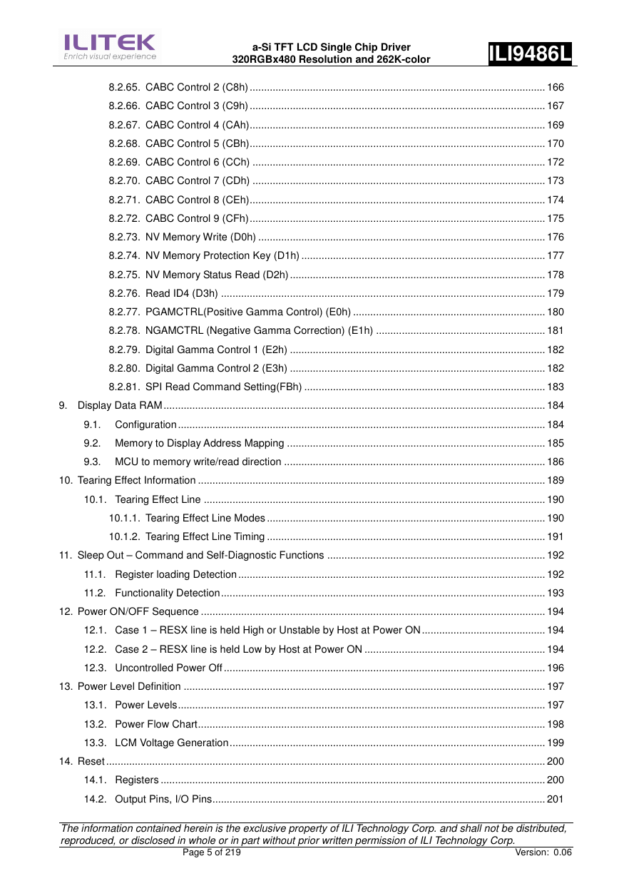
8.2.65. CABC Control 2 (C8h) ....................................................................................................... 166
8.2.66. CABC Control 3 (C9h) ....................................................................................................... 167
8.2.67. CABC Control 4 (CAh) ....................................................................................................... 169
8.2.68. CABC Control 5 (CBh) ....................................................................................................... 170
8.2.69. CABC Control 6 (CCh) ...................................................................................................... 172
8.2.70. CABC Control 7 (CDh) ...................................................................................................... 173
8.2.71. CABC Control 8 (CEh) ....................................................................................................... 174
8.2.72. CABC Control 9 (CFh) ....................................................................................................... 175
8.2.73. NV Memory Write (D0h) .................................................................................................... 176
8.2.74. NV Memory Protection Key (D1h) ..................................................................................... 177
8.2.75. NV Memory Status Read (D2h) ......................................................................................... 178
8.2.76. Read ID4 (D3h) ................................................................................................................. 179
8.2.77. PGAMCTRL(Positive Gamma Control) (E0h) ................................................................... 180
8.2.78. NGAMCTRL (Negative Gamma Correction) (E1h) ........................................................... 181
8.2.79. Digital Gamma Control 1 (E2h) ......................................................................................... 182
8.2.80. Digital Gamma Control 2 (E3h) ......................................................................................... 182
8.2.81. SPI Read Command Setting(FBh) .................................................................................... 183
9. Display Data RAM ..................................................................................................................................... 184
9.1. Configuration ................................................................................................................................ 184
9.2. Memory to Display Address Mapping .......................................................................................... 185
9.3. MCU to memory write/read direction ........................................................................................... 186
10. Tearing Effect Information ......................................................................................................................... 189
10.1. Tearing Effect Line ....................................................................................................................... 190
10.1.1. Tearing Effect Line Modes ................................................................................................. 190
10.1.2. Tearing Effect Line Timing ................................................................................................. 191
11. Sleep Out – Command and Self-Diagnostic Functions ............................................................................ 192
11.1. Register loading Detection ........................................................................................................... 192
11.2. Functionality Detection ................................................................................................................. 193
12. Power ON/OFF Sequence ........................................................................................................................ 194
12.1. Case 1 – RESX line is held High or Unstable by Host at Power ON ........................................... 194
12.2. Case 2 – RESX line is held Low by Host at Power ON ............................................................... 194
12.3. Uncontrolled Power Off ................................................................................................................ 196
13. Power Level Definition .............................................................................................................................. 197
13.1. Power Levels ................................................................................................................................ 197
13.2. Power Flow Chart ......................................................................................................................... 198
13.3. LCM Voltage Generation .............................................................................................................. 199
14. Reset ......................................................................................................................................................... 200
14.1. Registers ...................................................................................................................................... 200
14.2. Output Pins, I/O Pins .................................................................................................................... 201
The information contained herein is the exclusive property of ILI Technology Corp. and shall not be distributed,
reproduced, or disclosed in whole or in part without prior written permission of ILI Technology Corp.
Page 5 of 219
Version: 0.06
�
a-Si TFT LCD Single Chip Driver
320RGBx480 Resolution and 262K-color
ILI9486L
14.3. Input Pins ..................................................................................................................................... 201
14.4. Reset Timing ................................................................................................................................ 202
15. NV Memory Programming Flow ................................................................................................................ 203
16. Gamma Correction .................................................................................................................................... 204
17. Electrical Characteristics ........................................................................................................................... 206
17.1. Absolute Maximum Ratings ......................................................................................................... 206
17.2. DC Characteristics ....................................................................................................................... 207
17.2.1. DC characteristics for Power Lines ................................................................................... 207
17.2.2. DC characteristics for DSI LP mode .................................................................................. 208
17.2.3. Spike / Glitch Rejection...................................................................................................... 208
17.2.4. DC Characteristics for DSI HS mode ................................................................................ 209
17.2.5. DC Characteristics for Panel Driving ................................................................................. 211
17.3. AC Characteristics ....................................................................................................................... 212
17.3.1. Display Parallel 18/16/9/8-bit Interface Timing Characteristics (8080-series) ................... 212
17.3.2. Display Serial Interface Timing Characteristics (3-line SPI system) ................................. 214
17.3.3. Display Serial Interface Timing Characteristics (4-line SPI system) ................................. 215
17.3.4. Parallel 18/16-bit RGB Interface Timing Characteristics ................................................... 216
18. Application Circuit ..................................................................................................................................... 217
19. Revision History ........................................................................................................................................ 219
The information contained herein is the exclusive property of ILI Technology Corp. and shall not be distributed,
reproduced, or disclosed in whole or in part without prior written permission of ILI Technology Corp.
Page 6 of 219
Version: 0.06
�
1. Introduction
a-Si TFT LCD Single Chip Driver
320RGBx480 Resolution and 262K-color
ILI9486L
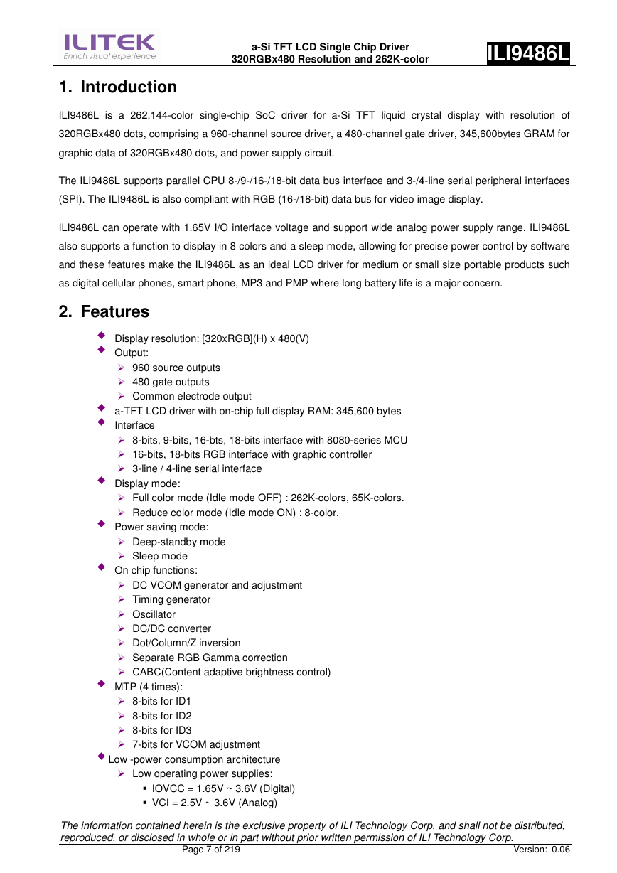
ILI9486L is a 262,144-color single-chip SoC driver for a-Si TFT liquid crystal display with resolution of
320RGBx480 dots, comprising a 960-channel source driver, a 480-channel gate driver, 345,600bytes GRAM for
graphic data of 320RGBx480 dots, and power supply circuit.
The ILI9486L supports parallel CPU 8-/9-/16-/18-bit data bus interface and 3-/4-line serial peripheral interfaces
(SPI). The ILI9486L is also compliant with RGB (16-/18-bit) data bus for video image display.
ILI9486L can operate with 1.65V I/O interface voltage and support wide analog power supply range. ILI9486L
also supports a function to display in 8 colors and a sleep mode, allowing for precise power control by software
and these features make the ILI9486L as an ideal LCD driver for medium or small size portable products such
as digital cellular phones, smart phone, MP3 and PMP where long battery life is a major concern.
2. Features
� Display resolution: [320xRGB](H) x 480(V)
� Output:
� 960 source outputs
� 480 gate outputs
� Common electrode output
� a-TFT LCD driver with on-chip full display RAM: 345,600 bytes
� Interface
� 8-bits, 9-bits, 16-bts, 18-bits interface with 8080-series MCU
� 16-bits, 18-bits RGB interface with graphic controller
� 3-line / 4-line serial interface
� Display mode:
� Full color mode (Idle mode OFF) : 262K-colors, 65K-colors.
� Reduce color mode (Idle mode ON) : 8-color.
� Power saving mode:
� Deep-standby mode
� Sleep mode
� On chip functions:
� DC VCOM generator and adjustment
� Timing generator
� Oscillator
� DC/DC converter
� Dot/Column/Z inversion
� Separate RGB Gamma correction
� CABC(Content adaptive brightness control)
� MTP (4 times):
� 8-bits for ID1
� 8-bits for ID2
� 8-bits for ID3
� 7-bits for VCOM adjustment
� Low -power consumption architecture
� Low operating power supplies:
� IOVCC = 1.65V ~ 3.6V (Digital)
� VCI = 2.5V ~ 3.6V (Analog)
The information contained herein is the exclusive property of ILI Technology Corp. and shall not be distributed,
reproduced, or disclosed in whole or in part without prior written permission of ILI Technology Corp.
Page 7 of 219
Version: 0.06
�
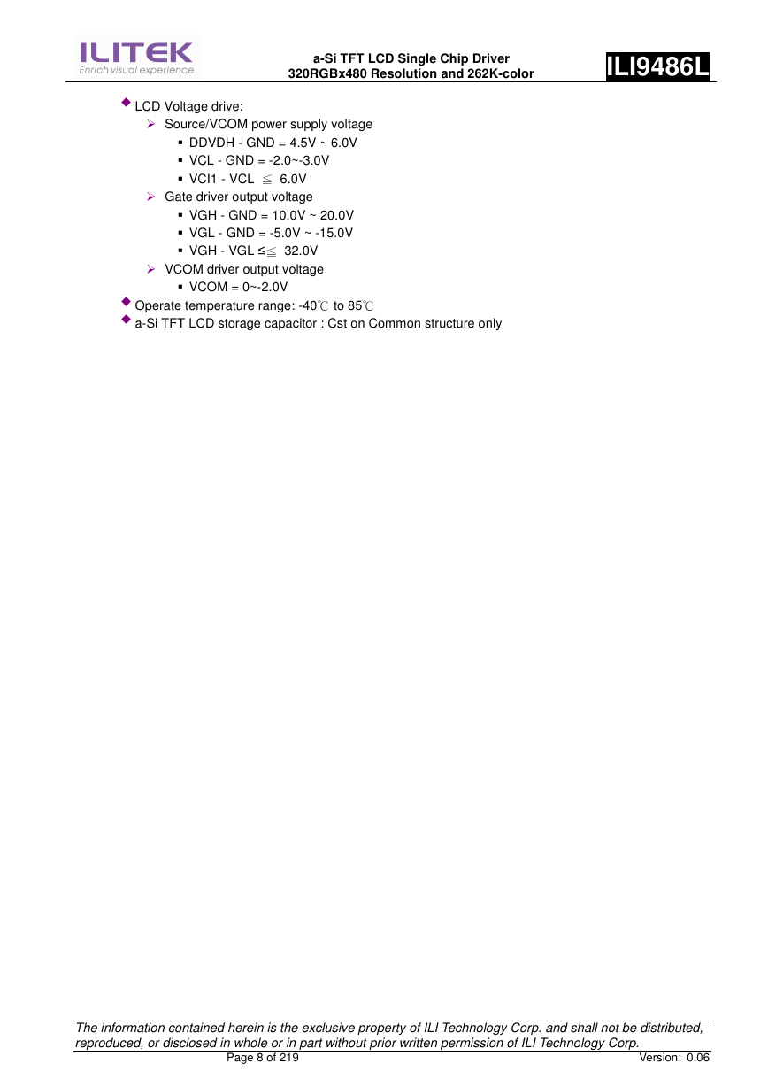
� LCD Voltage drive:
a-Si TFT LCD Single Chip Driver
320RGBx480 Resolution and 262K-color
ILI9486L
� Source/VCOM power supply voltage
� DDVDH - GND = 4.5V ~ 6.0V
� VCL - GND = -2.0~-3.0V
� VCI1 - VCL
6.0V
� Gate driver output voltage
� VGH - GND = 10.0V ~ 20.0V
� VGL - GND = -5.0V ~ -15.0V
� VGH - VGL ≤
32.0V
� VCOM driver output voltage
≦
≦
� VCOM = 0~-2.0V
� Operate temperature range: -40 to 85
� a-Si TFT LCD storage capacitor : Cst on Common structure only
℃
℃
The information contained herein is the exclusive property of ILI Technology Corp. and shall not be distributed,
reproduced, or disclosed in whole or in part without prior written permission of ILI Technology Corp.
Page 8 of 219
Version: 0.06
�



 2023年江西萍乡中考道德与法治真题及答案.doc
 2012年重庆南川中考生物真题及答案.doc
 2013年江西师范大学地理学综合及文艺理论基础考研真题.doc
 2020年四川甘孜小升初语文真题及答案I卷.doc
 2020年注册岩土工程师专业基础考试真题及答案.doc
 2023-2024学年福建省厦门市九年级上学期数学月考试题及答案.doc
 2021-2022学年辽宁省沈阳市大东区九年级上学期语文期末试题及答案.doc
 2022-2023学年北京东城区初三第一学期物理期末试卷及答案.doc
 2018上半年江西教师资格初中地理学科知识与教学能力真题及答案.doc
 2012年河北国家公务员申论考试真题及答案-省级.doc
 2020-2021学年江苏省扬州市江都区邵樊片九年级上学期数学第一次质量检测试题及答案.doc
 2022下半年黑龙江教师资格证中学综合素质真题及答案.doc