Project Cache Controller
1. Purpose
This project is intended to help you understand the cache architecture and its mechanism.
2. Problem
In this project, you will design a first-level data cache controller with Verilog HDL step by step.
You may need to review the knowledge about that language to make sure you do the project
smoothly.
3. Cache characteristics and mechanism
We take TMS320C64x DSP as an example. The TMS320C64x DSPs have a two-level memory
architecture for program and data, the first-level program cache (L1P), the first-level data cache
(L1D), and the second-level memory (L2). In this project, you only need to concern about the L1D
cache. Table 1 lists some specific parameters that may be used in this project.
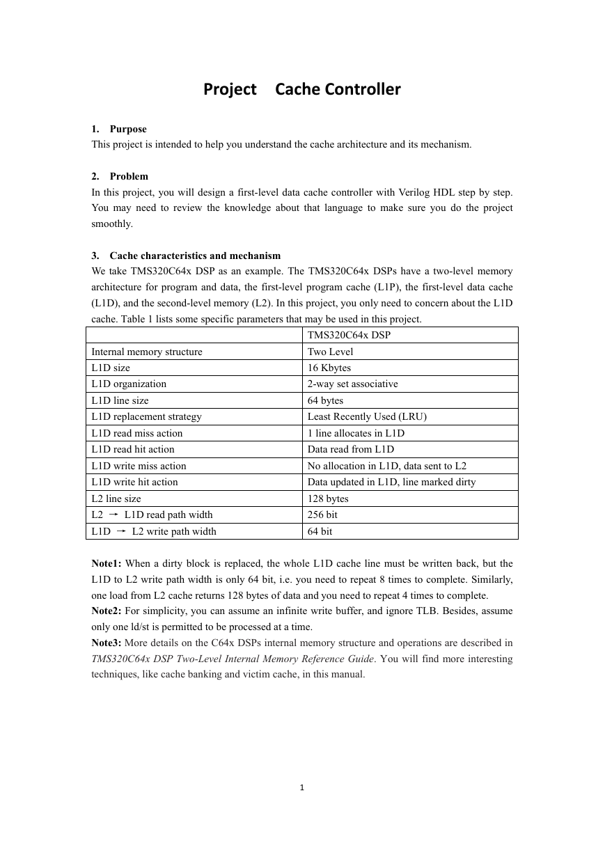
Internal memory structure
L1D size
L1D organization
L1D line size
L1D replacement strategy
L1D read miss action
L1D read hit action
L1D write miss action
L1D write hit action
L2 line size
L2 → L1D read path width
L1D → L2 write path width
TMS320C64x DSP
Two Level
16 Kbytes
2-way set associative
64 bytes
Least Recently Used (LRU)
1 line allocates in L1D
Data read from L1D
No allocation in L1D, data sent to L2
Data updated in L1D, line marked dirty
128 bytes
256 bit
64 bit
Note1: When a dirty block is replaced, the whole L1D cache line must be written back, but the
L1D to L2 write path width is only 64 bit, i.e. you need to repeat 8 times to complete. Similarly,
one load from L2 cache returns 128 bytes of data and you need to repeat 4 times to complete.
Note2: For simplicity, you can assume an infinite write buffer, and ignore TLB. Besides, assume
only one ld/st is permitted to be processed at a time.
Note3: More details on the C64x DSPs internal memory structure and operations are described in
TMS320C64x DSP Two-Level Internal Memory Reference Guide. You will find more interesting
techniques, like cache banking and victim cache, in this manual.
1
�
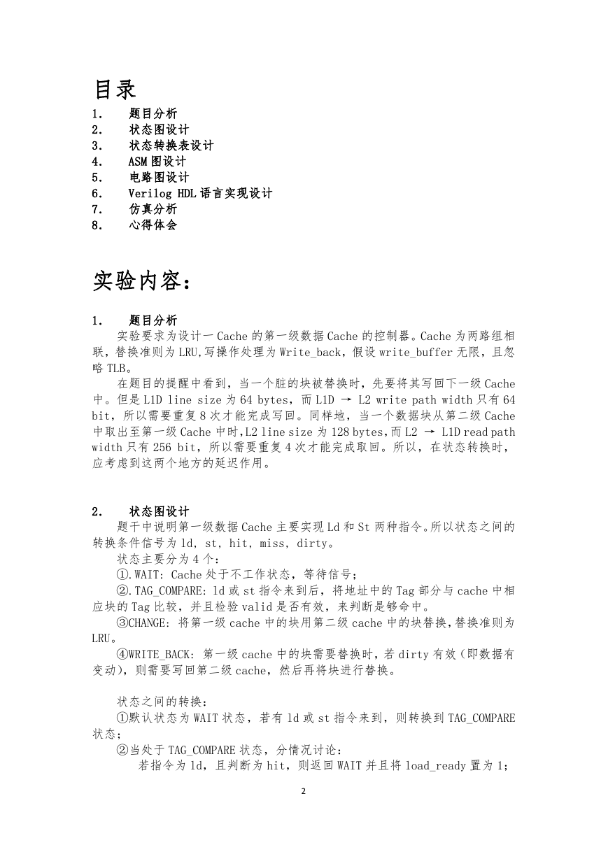
目录
1. 题目分析
2. 状态图设计
3. 状态转换表设计
4. ASM 图设计
5. 电路图设计
6. Verilog HDL 语言实现设计
7. 仿真分析
8. 心得体会
实验内容:
1. 题目分析
实验要求为设计一 Cache 的第一级数据 Cache 的控制器。Cache 为两路组相
联,替换准则为 LRU,写操作处理为 Write_back,假设 write_buffer 无限,且忽
略 TLB。
在题目的提醒中看到,当一个脏的块被替换时,先要将其写回下一级 Cache
中。但是 L1D line size 为 64 bytes,而 L1D → L2 write path width 只有 64
bit,所以需要重复 8 次才能完成写回。同样地,当一个数据块从第二级 Cache
中取出至第一级 Cache 中时,L2 line size 为 128 bytes,而 L2 → L1D read path
width 只有 256 bit,所以需要重复 4 次才能完成取回。所以,在状态转换时,
应考虑到这两个地方的延迟作用。
2. 状态图设计
题干中说明第一级数据 Cache 主要实现 Ld 和 St 两种指令。所以状态之间的
转换条件信号为 ld, st, hit, miss, dirty。
状态主要分为 4 个:
①.WAIT: Cache 处于不工作状态,等待信号;
②.TAG_COMPARE: ld 或 st 指令来到后,将地址中的 Tag 部分与 cache 中相
应块的 Tag 比较,并且检验 valid 是否有效,来判断是够命中。
③CHANGE: 将第一级 cache 中的块用第二级 cache 中的块替换,替换准则为
LRU。
④WRITE_BACK: 第一级 cache 中的块需要替换时,若 dirty 有效(即数据有
变动),则需要写回第二级 cache,然后再将块进行替换。
状态之间的转换:
①默认状态为 WAIT 状态,若有 ld 或 st 指令来到,则转换到 TAG_COMPARE
状态;
②当处于 TAG_COMPARE 状态,分情况讨论:
若指令为 ld,且判断为 hit,则返回 WAIT 并且将 load_ready 置为 1;
2
�
若指令为 ld,且判断为 miss,检验 dirty 为有效时,由题干知 L1D read
miss action,1 line allocates in L1D(读分配),所以需要将块中
数据写回缓冲,即转换到状态 TAG_COMPARE,同时置 write_l2 为 1;
若指令为 ld,且判断为 miss,检验 dirty 为无效时,即块中数据没有
变化,可直接替换,则转换到状态 CHANGE,同时置 write_l1,read_l2
为 1;
若指令为 st,且判断为 hit,则返回 WAIT,且置 write_l1 为 1;
若指令为 st,且判断为 miss,由题干知 L1D write miss action,No
allocation in L1D, data sent to L2(写不分配),则转换到状态
WRITE_BACK,同时置 write_l2 为 1;
③.当处于状态 CHANGE 时: 当接收到信号 l2_ack(从第二级 cache 取回的数
据已经到达),则转换到状态 TAG_COMPARE,同时将 hit 置为 1;
④.当处于状态 WRITE_BACK: 这个状态相当于 TAG_COMPARE 与 CHANGE 状态中
间的一个缓冲分流区,在 TAG_COMPARE 判断 miss 时,若指令为 st 时,则此状态
就能完成任务,转换到状态 WAIT;若指令为 ld,则将执行权传到状态 CHANGE;
同时置 read_l2,write_l1 为 1;
NOTE: 题目分析中,当一个脏的块被替换时,由于线宽限制,需要重复 8
次才能完成写回。同样地,当一个数据块从第二级 Cache 中取出至第一级 Cache
中时需要重复 4 次才能完成取回。所以,在 WRITE_BACK 状态,且指令为 ld 时,
应考虑 8 个时钟周期的延迟。同样地,在 CHANGE 状态时,应考虑数据从第二级
cache 取回第一级 cache 时的 4 个周期的延迟。考虑同计时器实现延迟作用,4
周期延迟和 8 周期延迟信号分别设为 c4 和 c8。
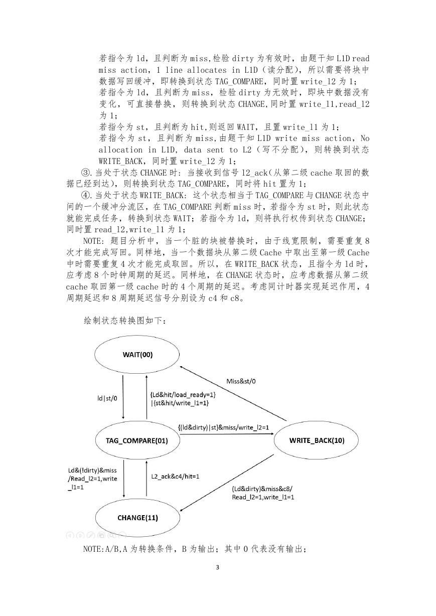
绘制状态转换图如下:
NOTE:A/B,A 为转换条件,B 为输出;其中 0 代表没有输出;
3
�
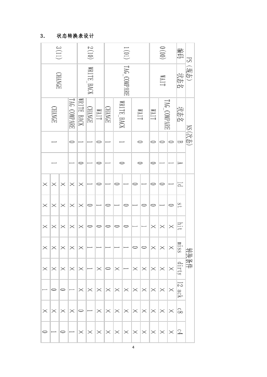
3. 状态转换表设计
4
�
4. ASM 图设计
开始
WAIT
N
Ld|st?
TAG_COMPARE
Hit=1
Y
N
Dirty?
N
Read_l2=1
Write_l1=1
CHANGE
11
Load_ready=1
Write_l1=1
Y
Ld?
N
Write_l2=1
WRITE_BACK
10
Y
St?
N
C8?
Y
L2_ack?
Y
C4?
Y
N
N
N
5
�
5. 电路图设计
经考虑,采用多路选择器型控制器。
采用多路选择器作为控制器状态触发器的次态激励函数的生成电路,不仅能
使控制器的设计过程标准化,而且可以使整个控制器电路“清晰明朗”。当 ASM
图有变化时,只需对电路中相应地 MUX 的输入做适当修改就可以。
观察 3 中的状态转换表,电路采用 2 个 D 型触发器 FA 和 FB,相应地需要两
个 4 位数据选择器。(电路图中 4 位选择器由 8 位选择器修改)。多路选择器的控
制端分别与触发器的 Q 输出端相连。标之为 Qa 和 Qb。当状态 Qa=0,Qb=0 时,选
择器的 0 号输入端(数据端)被选中,根据状态转换表,利用
NS
CPS
公
式,将次态变量中的真值为 1 的各项按转换条件写出,于是得
MUXA(0)=ld.st’+ld’.st;
MUXA(1)=ld.st’.miss.dirty’;
MUXA(2)=ld.st’.miss.dirty.c8;
MUXA(3)=1
MUXB(0)=0;
MUXB(1)=(ld’.st+ld.st’).miss;
MUXB(2)=ld.st’.miss.dirty+c8;
MUXB(3)=l2_ack’+c4’;
此时用 PS 作为 MUX 的地址输入,用转换条件作为 MUX 的数据输入
信号输出为:
Load_ready=ld.hit.(01);
Write_l1=st.hit.(01)+ld.(dirty’).miss.(01)+ld.dirty.miss.c8.(10)
;
Read_l2=ld.(dirty’).miss.(01)+ld.dirty.miss.c8.(10);
Write_l2=ld.dirty.miss+st.miss;
Hit=l2_ack.c4.(11)
电路元器件列表
电路图用 Altium Designer 绘制,见下页。
6
�
7
�
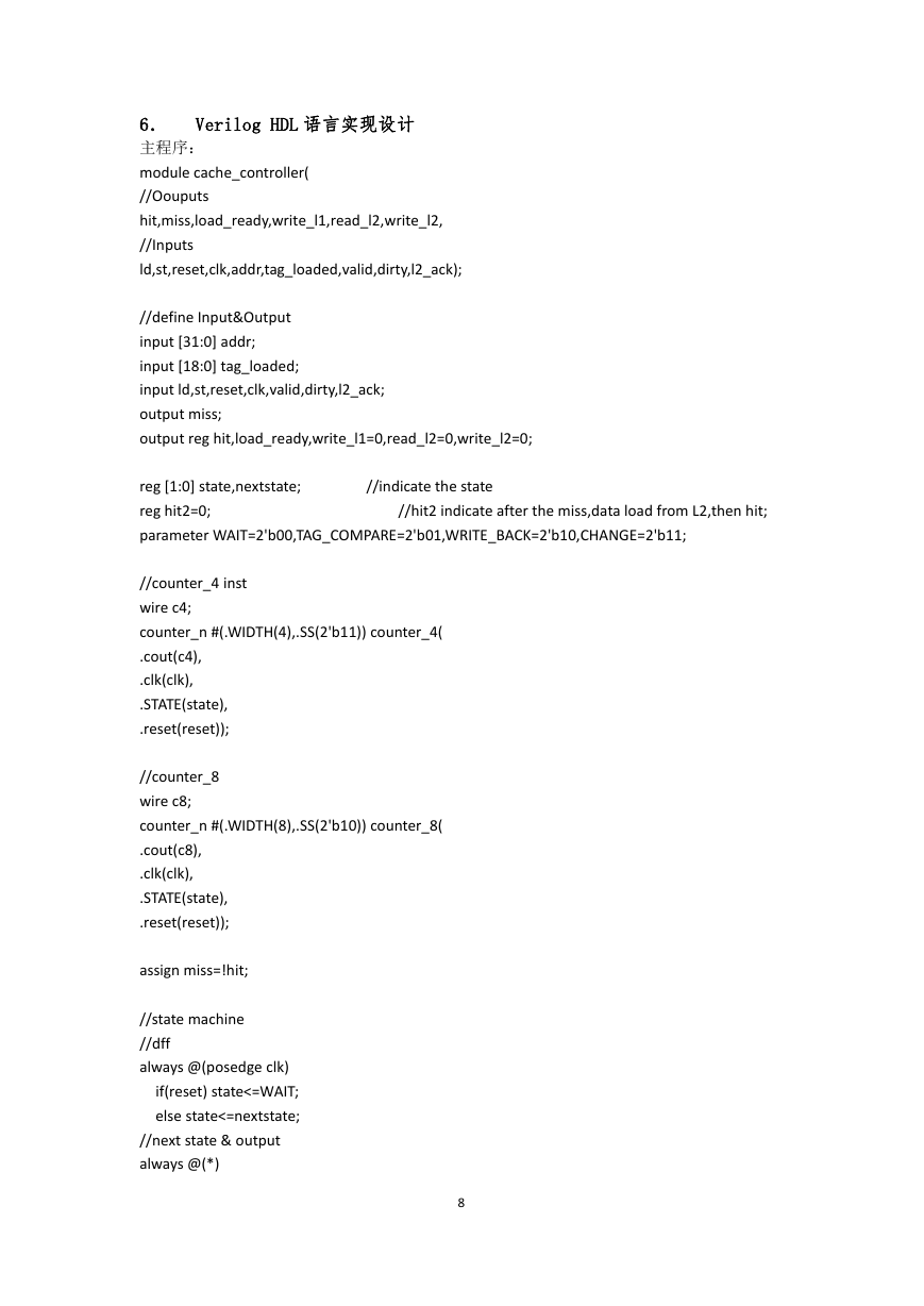
6. Verilog HDL 语言实现设计
主程序:
module cache_controller(
//Oouputs
hit,miss,load_ready,write_l1,read_l2,write_l2,
//Inputs
ld,st,reset,clk,addr,tag_loaded,valid,dirty,l2_ack);
//define Input&Output
input [31:0] addr;
input [18:0] tag_loaded;
input ld,st,reset,clk,valid,dirty,l2_ack;
output miss;
output reg hit,load_ready,write_l1=0,read_l2=0,write_l2=0;
reg [1:0] state,nextstate;
reg hit2=0;
parameter WAIT=2'b00,TAG_COMPARE=2'b01,WRITE_BACK=2'b10,CHANGE=2'b11;
//indicate the state
//hit2 indicate after the miss,data load from L2,then hit;
//counter_4 inst
wire c4;
counter_n #(.WIDTH(4),.SS(2'b11)) counter_4(
.cout(c4),
.clk(clk),
.STATE(state),
.reset(reset));
//counter_8
wire c8;
counter_n #(.WIDTH(8),.SS(2'b10)) counter_8(
.cout(c8),
.clk(clk),
.STATE(state),
.reset(reset));
assign miss=!hit;
//state machine
//dff
always @(posedge clk)
if(reset) state<=WAIT;
else state<=nextstate;
//next state & output
always @(*)
8
�




 2023年江西萍乡中考道德与法治真题及答案.doc
 2012年重庆南川中考生物真题及答案.doc
 2013年江西师范大学地理学综合及文艺理论基础考研真题.doc
 2020年四川甘孜小升初语文真题及答案I卷.doc
 2020年注册岩土工程师专业基础考试真题及答案.doc
 2023-2024学年福建省厦门市九年级上学期数学月考试题及答案.doc
 2021-2022学年辽宁省沈阳市大东区九年级上学期语文期末试题及答案.doc
 2022-2023学年北京东城区初三第一学期物理期末试卷及答案.doc
 2018上半年江西教师资格初中地理学科知识与教学能力真题及答案.doc
 2012年河北国家公务员申论考试真题及答案-省级.doc
 2020-2021学年江苏省扬州市江都区邵樊片九年级上学期数学第一次质量检测试题及答案.doc
 2022下半年黑龙江教师资格证中学综合素质真题及答案.doc