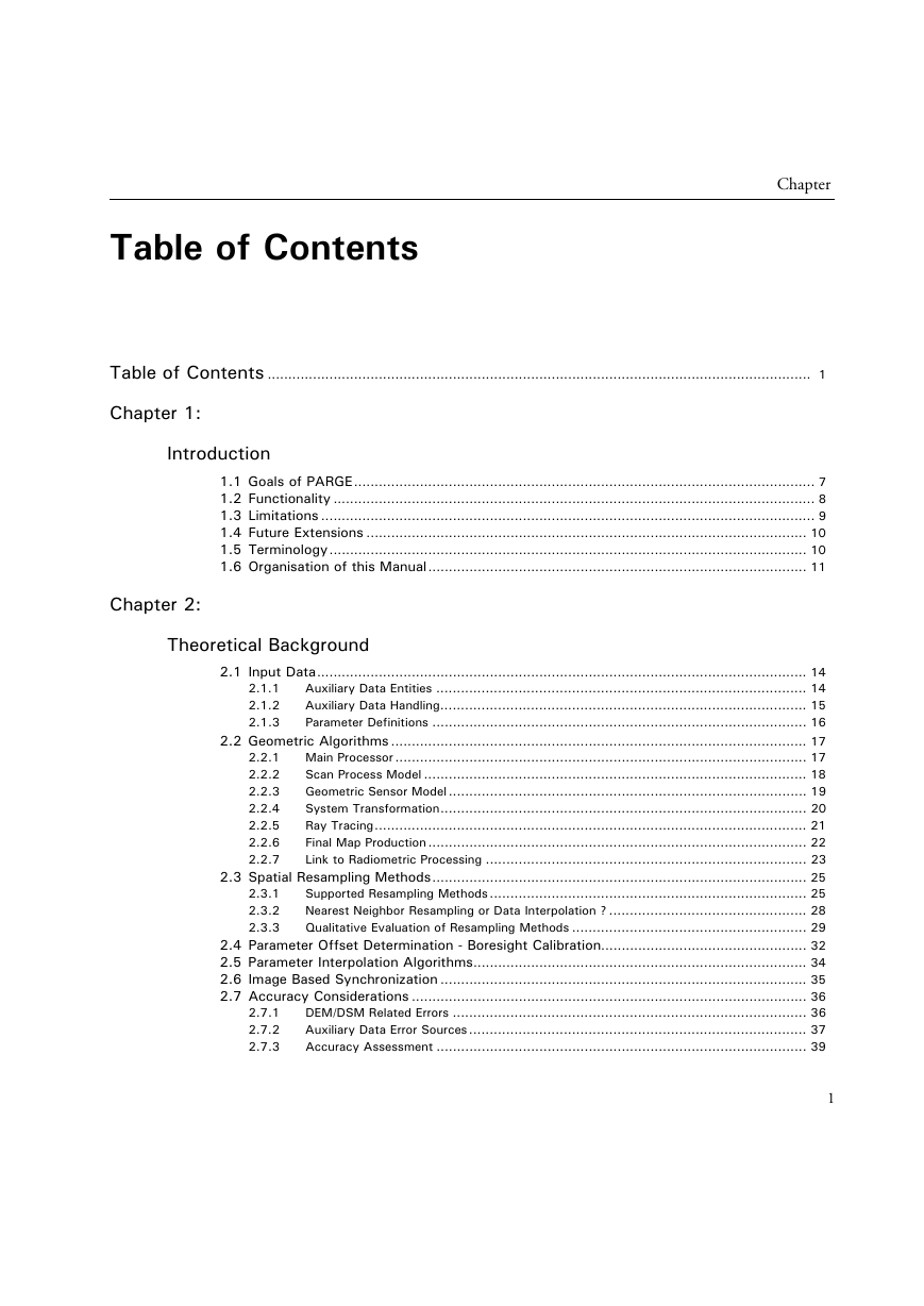
Table of Contents
Chapter 1: Introduction
1.1 Goals of PARGE
1.2 Functionality
a) Compatibility
b) Auxiliary data functions
c) Processing options
d) Supporting abilities
1.3 Limitations
1.4 Future Extensions
1.5 Terminology
1.6 Organisation of this Manual
Chapter 2: Theoretical Background
2.1 Input Data
2.1.1 Auxiliary Data Entities
a) Aircraft Position and Attitude Data
b) Digital Elevation Model
c) Image/Sensor Data Acquisition Information
2.1.2 Auxiliary Data Handling
2.1.3 Parameter Definitions
2.2 Geometric Algorithms
2.2.1 Main Processor
a) Calculate the current observation geometry (see Figure 2.1)
b) Find the intersection point on the surface
c) Find the image coordinates
d) Complete Mapping Array
e) Final Processing
2.2.2 Scan Process Model
2.2.3 Geometric Sensor Model
2.2.4 System Transformation
2.2.5 Ray Tracing
2.2.6 Final Map Production
2.2.7 Link to Radiometric Processing
2.3 Spatial Resampling Methods
2.3.1 Supported Resampling Methods
a) Nearest Neighbor Methods
b) Natural Neighbor Interpolation
c) Linear Interpolation Methods
d) Bilinear Interpolation
e) Spatial Binning
f) Other Methods
2.3.2 Nearest Neighbor Resampling or Data Interpolation ?
2.3.3 Qualitative Evaluation of Resampling Methods
2.4 Parameter Offset Determination - Boresight Calibration
2.5 Parameter Interpolation Algorithms
2.6 Image Based Synchronization
2.7 Accuracy Considerations
2.7.1 DEM/DSM Related Errors
2.7.2 Auxiliary Data Error Sources
2.7.3 Accuracy Assessment
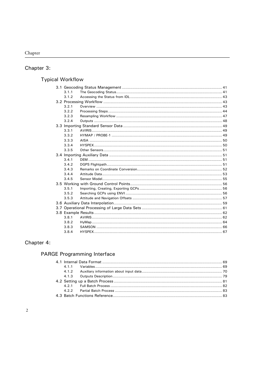
Chapter 3: Typical Workflow
3.1 Geocoding Status Management
3.1.1 The Geocoding Status
3.1.2 Accessing the Status from IDL
3.2 Processing Workflow
3.2.1 Overview
3.2.2 Processing Steps
a) Importing the scanner data
b) Checking the auxiliary data
c) Saving the current status
d) Defining the DEM
e) Input GCPs
f) Setting the offsets for roll and pitch and heading
g) GPS data and altitude offsets
h) Checking the parameters
i) Running the main processor
j) Creating orthorectified results
k) Creating a mosaicked output
3.2.3 Resampling Workflow
a) Acquisition geometry (IGM processing)
b) Cartographic geometry (MAP processing)
3.2.4 Outputs
3.3 Importing Standard Sensor Data
3.3.1 AVIRIS
3.3.2 HYMAP / PROBE-1
3.3.3 AISA
3.3.4 HYSPEX
3.3.5 Other Sensors
3.4 Importing Auxiliary Data
3.4.1 DEM
3.4.2 DGPS Flightpath
3.4.3 Remarks on Coordinate Conversion
3.4.4 Attitude Data
a) Heading
b) Roll:
c) Pitch:
d) Yaw:
3.4.5 Sensor Model
3.5 Working with Ground Control Points
3.5.1 Importing, Creating, Exporting GCPs
3.5.2 Searching GCPs using ENVI
3.5.3 Attitude and Navigation Offsets
3.6 Auxiliary Data Interpolation
3.7 Operational Processing of Large Data Sets
a) Prepare the DEM
b) Do the boresight calibration
c) Setup a script
d) Do the processing
e) Mosaic your results
3.8 Example Results
3.8.1 AVIRIS
3.8.2 HyMap
3.8.3 SAMSON
3.8.4 HYSPEX
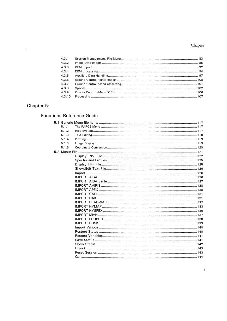
Chapter 4: PARGE Programming Interface
4.1 Internal Data Format
4.1.1 Variables
4.1.2 Auxiliary information about input data
a) Image
b) Sensor
c) DEM
d) Auxiliary
e) Result
f) Preferences
4.1.3 Outputs Description
4.2 Setting up a Batch Process
4.2.1 Full Batch Process
4.2.2 Partial Batch Process
4.3 Batch Functions Reference
4.3.1 Session Management, File Menu
4.3.2 Image Data Import
a) AVIRIS Functions
b) HYMAP Functions
c) PROBE-1 functions
d) AISA functions
e) ROSIS functions
f) MIVIS functions
g) DAIS Functions
h) HYSPEX Functions
i) Headwall HYPERSPEC / UAV spectrometers import
4.3.3 DEM Import
4.3.4 DEM processing
4.3.5 Auxiliary Data Handling
4.3.6 Ground Control Points Import
4.3.7 Ground Control based Offsetting
4.3.8 Special
4.3.9 Quality Control (Menu ‘QC’)
4.3.10 Processing
Chapter 5: Functions Reference Guide
5.1 Generic Menu Elements
5.1.1 The PARGE Menu
5.1.2 Help System
5.1.3 Text Editing
5.1.4 Plotting
5.1.5 Image Display
5.1.6 Coordinate Conversion
5.2 Menu: File
Display ENVI File
Spectra and Profiles
Display TIFF File
Show/Edit Text File
Import
IMPORT AISA
IMPORT AISA Eagle
IMPORT AVIRIS
IMPORT APEX
IMPORT CASI
IMPORT DAIS
IMPORT HEADWALL
IMPORT HYMAP
IMPORT HYSPEX
IMPORT Mivis
IMPORT PROBE-1
IMPORT ROSIS
Import Various
Restore Status
Restore Variables
Save Status
Show Status
Export
Reset Session
Quit
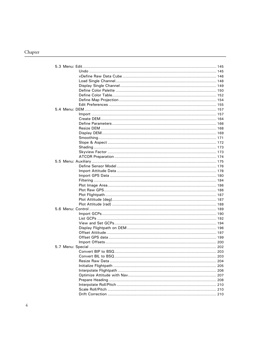
5.3 Menu: Edit
Undo
vDefine Raw Data Cube
Load Single Channel
Display Single Channel
Define Color Palette
Define Color Table
Define Map Projection
Edit Preferences
5.4 Menu: DEM
Import
Create DEM
Define Parameters
Resize DEM
Display DEM
Smoothing
Slope & Aspect
Shading
Skyview Factor
ATCOR Preparation
5.5 Menu: Auxiliary
Define Sensor Model
Import Attitude Data
Import GPS Data
Filtering
Plot Image Area
Plot Raw GPS
Plot Flightpath
Plot Attitude [deg]
Plot Attitude [rad]
5.6 Menu: Control
Import GCPs
List GCPs
View and Set GCPs
Display Flightpath on DEM
Offset Attitude
Offset GPS data
Import Offsets
5.7 Menu: Special
Convert BIP to BSQ
Convert BIL to BSQ
Resize Raw Data
Initialize Flightpath
Interpolate Flightpath
Optimize Attitude with Nav.
Prepare Heading
Interpolate Roll/Pitch
Scale Roll/Pitch
Drift Correction
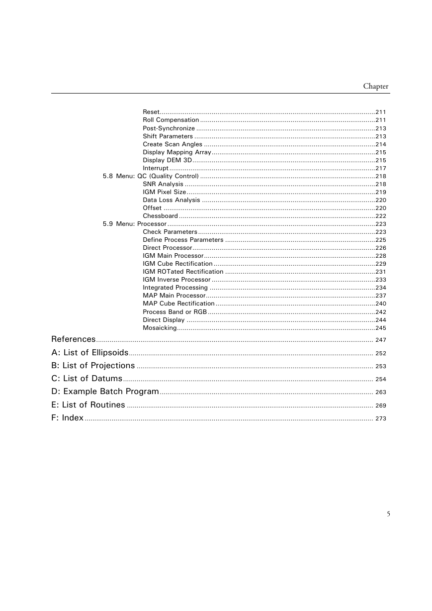
Reset
Roll Compensation
Post-Synchronize
Shift Parameters
Create Scan Angles
Display Mapping Array
Display DEM 3D
Interrupt
5.8 Menu: QC (Quality Control)
SNR Analysis
IGM Pixel Size
Data Loss Analysis
Offset
Chessboard
5.9 Menu: Processor
Check Parameters
Define Process Parameters
Direct Processor
IGM Main Processor
IGM Cube Rectification
IGM ROTated Rectification
IGM Inverse Processor
Integrated Processing
MAP Main Processor
MAP Cube Rectification
Process Band or RGB
Direct Display
Mosaicking
References
A: List of Ellipsoids
B: List of Projections
C: List of Datums
D: Example Batch Program
E: List of Routines
F: Index



 2023年江西萍乡中考道德与法治真题及答案.doc
 2012年重庆南川中考生物真题及答案.doc
 2013年江西师范大学地理学综合及文艺理论基础考研真题.doc
 2020年四川甘孜小升初语文真题及答案I卷.doc
 2020年注册岩土工程师专业基础考试真题及答案.doc
 2023-2024学年福建省厦门市九年级上学期数学月考试题及答案.doc
 2021-2022学年辽宁省沈阳市大东区九年级上学期语文期末试题及答案.doc
 2022-2023学年北京东城区初三第一学期物理期末试卷及答案.doc
 2018上半年江西教师资格初中地理学科知识与教学能力真题及答案.doc
 2012年河北国家公务员申论考试真题及答案-省级.doc
 2020-2021学年江苏省扬州市江都区邵樊片九年级上学期数学第一次质量检测试题及答案.doc
 2022下半年黑龙江教师资格证中学综合素质真题及答案.doc