Technical support
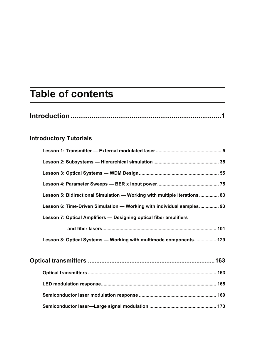
Table of contents
Introduction
Tutorials
Advanced simulation project sections
Notes:
Notes:
Lesson 1: Transmitter - External modulated laser
Main parts of the GUI
Project layout
Dockers
Status Bar
Menu bar
Auto connect feature
Visualizing the results
Visualizers and data monitors
Component parameters
Display parameters in the layout
Parameter units
Info-Window
Zoom, Pan, and Trace tools
Notes:
Lesson 2: Subsystems - Hierarchical simulation
Subsystem properties - name and icon
Component Library
Notes:
Lesson 3: Optical Systems - WDM Design
Global parameters
Transmitters
Parameter groups
Fiber + EDFA spans
BER Analyzer
Lesson 4: Parameter Sweeps - BER x Input power
Lesson 5: Bidirectional Simulation - Working with multiple iterations
A basic bidirectional simulation
System setup
Running the simulation
Viewing the results - system deadlock
Using delays
Viewing the results
Using Iterations parameter
Viewing the results
Cascading devices
Tools library
Lesson 6: Time-Driven Simulation - Working with individual samples
A Time-Driven Simulation
Global parameters
System setup
Running the simulation
Viewing the results
System setup - Individual Samples
Viewing the results
Important remarks
Filtering using individual samples
Viewing the results
Notes:
Lesson 7: Optical Amplifiers - Designing optical fiber amplifiers and fiber lasers
Optical Amplifiers
Global parameters
System setup
Signals tab
Running the simulation
Viewing the results
Running the simulation
Viewing the results
Viewing the gain versus wavelength
Running the simulation
Viewing the results
Building the graph Gain x Wavelength and Noise Figure x Wavelength
Optimizing the Fiber length
Viewing the results
Setting up the Optimization
Lesson 8: Optical Systems - Working with multimode components
Multimode Transmitters
Global parameters
System setup
Spatial effects tab
Running the simulation
Viewing the results
Multimode components and Free-Space Propagation
Spatial connector: translating the optical field
Viewing the results
Spatial connector: rotating the optical field
Viewing the results
Thin Lens: focusing the optical beam
Viewing the results
Spatial Aperture: limiting the optical field
Viewing the results
Multimode Receivers
System setup
Viewing the results
Multimode Fibers and Links
System setup
Calculating Fiber Properties
Viewing the fiber properties
Viewing the results
Optical transmitters
Notes:
Optical transmitters
LED modulation response
References
Semiconductor laser modulation response
References
Semiconductor laser-Large signal modulation
References:
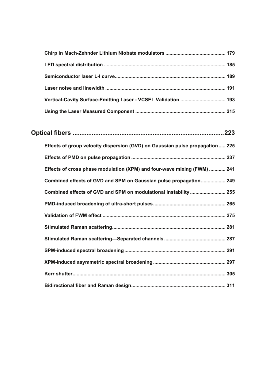
Chirp in Mach-Zehnder Lithium Niobate modulators
References:
LED spectral distribution
References
Semiconductor laser L-I curve
Laser noise and linewidth
Notes:
Vertical-Cavity Surface-Emitting Laser - VCSEL Validation
Creating a Project
First device: 863 nm laser
Parameter setup
Graphs
Parameter sweep
Running the simulation
Viewing the results
Parameter fitting
Second device: 683 nm laser
Parameter setup
Graphs
Parameter sweep
Viewing the results
Parameter fitting
Third device: 1550 nm laser
Parameter setup
Parameter sweep
Viewing the results
References
Using the Laser Measured Component
Case 1: Setting the measured values Z, Y, P1 and Ith to obtain the correspondent physical parameters:
Case 2: Setting the measured values Z, Y, P, Ith and also setting an average RIN value to obtain the correspondent physical parameters
References:
Optical fibers
Notes:
Effects of group velocity dispersion (GVD) on Gaussian pulse propagation
Reference:
Notes:
Effects of PMD on pulse propagation
References:
Effects of cross phase modulation (XPM) and four-wave mixing (FWM)
References:
Notes:
Combined effects of GVD and SPM on Gaussian pulse propagation
Reference:
Combined effects of GVD and SPM on modulational instability
Reference:
Notes:
PMD-induced broadening of ultra-short pulses
References:
Validation of FWM effect
Reference:
Stimulated Raman scattering
References
Notes:
Stimulated Raman scattering-Separated channels
Reference:
SPM-induced spectral broadening
References:
XPM-induced asymmetric spectral broadening
References
Kerr shutter
References:
Bidirectional fiber and Raman design
Notes:
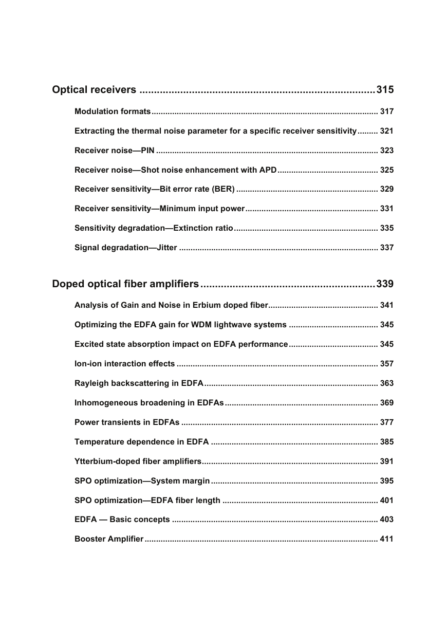
Optical receivers
Notes:
Modulation formats
Notes:
Extracting the thermal noise parameter for a specific receiver sensitivity
Receiver noise-PIN
Receiver noise-Shot noise enhancement with APD
Notes:
Receiver sensitivity-Bit error rate (BER)
Receiver sensitivity-Minimum input power
Notes:
Sensitivity degradation-Extinction ratio
Signal degradation-Jitter
Doped optical fiber amplifiers
Notes:
Analysis of Gain and Noise in Erbium doped fiber
Reference:
Optimizing the EDFA gain for WDM lightwave systems
References:
Excited state absorption impact on EDFA performance
References:
Ion-ion interaction effects
Homogeneous Upconversion
Pair-Induced Quenching
References:
Rayleigh backscattering in EDFA
References:
Inhomogeneous broadening in EDFAs
References
Notes:
Power transients in EDFAs
References:
Temperature dependence in EDFA
References:
Ytterbium-doped fiber amplifiers
References:
SPO optimization-System margin
SPO optimization-EDFA fiber length
Notes:
EDFA - Basic concepts
Layout Gain Spectrum
Layout Gain Saturation
Layout Amplifier Noise
Booster Amplifier
Notes:
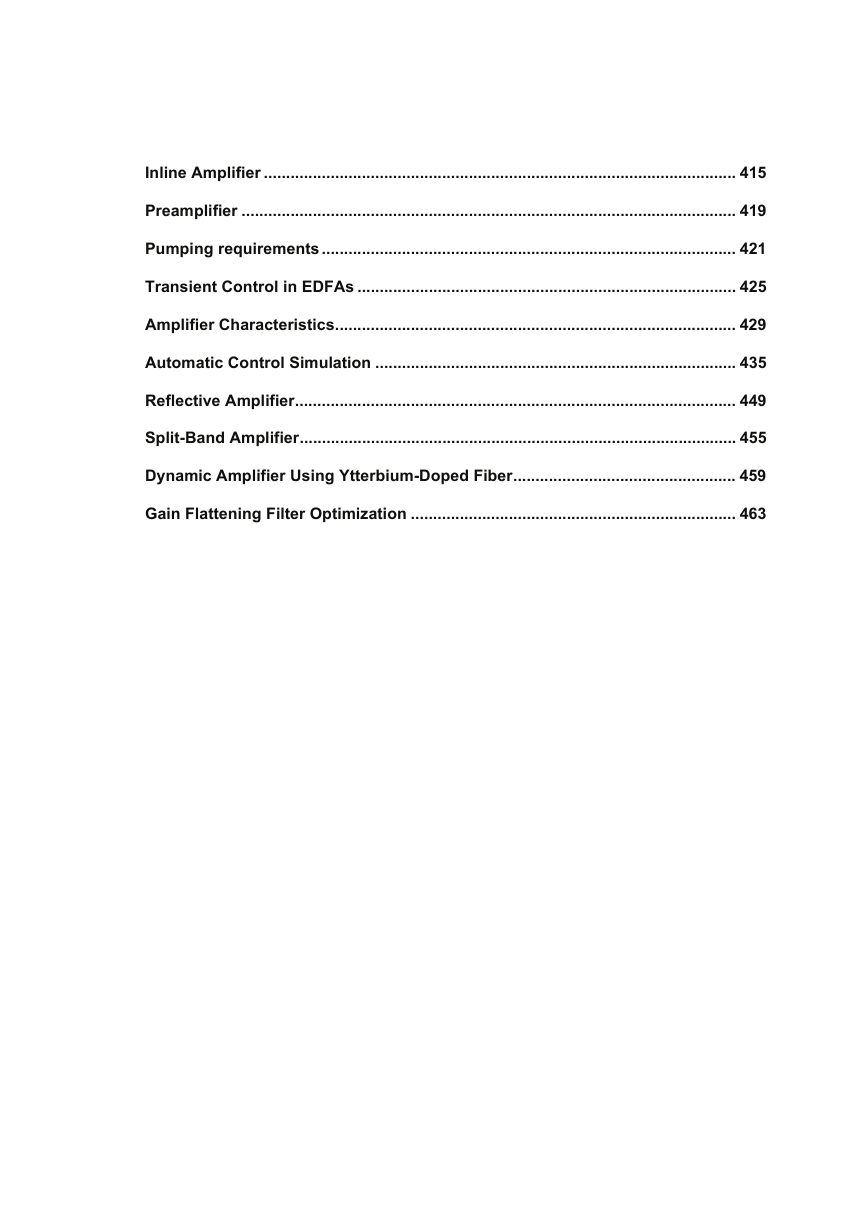
Inline Amplifier
Notes:
Preamplifier
Pumping requirements
Transient Control in EDFAs
Gain clamping
References
Amplifier Characteristics
Loading the project
Running the simulation
Viewing the results
Notes:
Automatic Control Simulation
Loading the project
Automatic Gain Control
Automatic Power Control
Automatic Peak Power Control
Optimization
Running the simulation
Viewing the results
Notes:
Erbium-doped Fiber Laser
Loading the project
Running the simulation
Viewing results
Notes:
Reflective Amplifier
Loading the project
Running the simulation
Viewing results
Notes:
Split-Band Amplifier
Loading the project
Running the simulation
Viewing results
Dynamic Amplifier Using Ytterbium-Doped Fiber
Notes:
Gain Flattening Filter Optimization
Notes:



 2023年江西萍乡中考道德与法治真题及答案.doc
 2012年重庆南川中考生物真题及答案.doc
 2013年江西师范大学地理学综合及文艺理论基础考研真题.doc
 2020年四川甘孜小升初语文真题及答案I卷.doc
 2020年注册岩土工程师专业基础考试真题及答案.doc
 2023-2024学年福建省厦门市九年级上学期数学月考试题及答案.doc
 2021-2022学年辽宁省沈阳市大东区九年级上学期语文期末试题及答案.doc
 2022-2023学年北京东城区初三第一学期物理期末试卷及答案.doc
 2018上半年江西教师资格初中地理学科知识与教学能力真题及答案.doc
 2012年河北国家公务员申论考试真题及答案-省级.doc
 2020-2021学年江苏省扬州市江都区邵樊片九年级上学期数学第一次质量检测试题及答案.doc
 2022下半年黑龙江教师资格证中学综合素质真题及答案.doc