Application Note, V1.0, Oct 2006
AP08018
XC866
Start-up Control Algorithm for Sensorless and Variable Load BLDC
Control Using Variable Inductance Sensing Method
Microcontrollers
�
Edition 2006-11-24
Published by
Infineon Technologies AG
81726 München, Germany
© Infineon Technologies AG 2006.
All Rights Reserved.
LEGAL DISCLAIMER
THE INFORMATION GIVEN IN THIS APPLICATION NOTE IS GIVEN AS A HINT FOR THE
IMPLEMENTATION OF THE INFINEON TECHNOLOGIES COMPONENT ONLY AND SHALL NOT BE
REGARDED AS ANY DESCRIPTION OR WARRANTY OF A CERTAIN FUNCTIONALITY, CONDITION OR
QUALITY OF THE INFINEON TECHNOLOGIES COMPONENT. THE RECIPIENT OF THIS APPLICATION
NOTE MUST VERIFY ANY FUNCTION DESCRIBED HEREIN IN THE REAL APPLICATION. INFINEON
TECHNOLOGIES HEREBY DISCLAIMS ANY AND ALL WARRANTIES AND LIABILITIES OF ANY KIND
(INCLUDING WITHOUT LIMITATION WARRANTIES OF NON-INFRINGEMENT OF INTELLECTUAL
PROPERTY RIGHTS OF ANY THIRD PARTY) WITH RESPECT TO ANY AND ALL INFORMATION GIVEN
IN THIS APPLICATION NOTE.
Information
For further information on technology, delivery terms and conditions and prices please contact your nearest
Infineon Technologies Office (www.infineon.com).
Warnings
Due to technical requirements components may contain dangerous substances. For information on the types
in question please contact your nearest Infineon Technologies Office.
Infineon Technologies Components may only be used in life-support devices or systems with the express
written approval of Infineon Technologies, if a failure of such components can reasonably be expected to
cause the failure of that life-support device or system, or to affect the safety or effectiveness of that device or
system. Life support devices or systems are intended to be implanted in the human body, or to support
and/or maintain and sustain and/or protect human life. If they fail, it is reasonable to assume that the health
of the user or other persons may be endangered.
�
AP08018
Start-up Control Algorithm for Sensorless and Variable Load
BLDC Control Using Variable Inductance Sensing Method
2006-10
none
V1.0
AP08018
Revision History:
Previous Version:
We Listen to Your Comments
Any information within this document that you feel is wrong, unclear or missing at all?
Your feedback will help us to continuously improve the quality of this document.
Please send your proposal (including a reference to this document) to:
mcdocu.comments@infineon.com
Application Note
3
V1.0, 2006-10
�
AP08018
Start-up Control Algorithm for Sensorless and Variable Load
BLDC Control Using Variable Inductance Sensing Method
Table of Contents
1
Page
INTRODUCTION.................................................................................................................................................. 5
1.1
RAMP UP METHOD........................................................................................................................................ 5
VARIABLE INDUCTANCE SENSING METHOD.......................................................................................... 6
HARDWARE IMPLEMENTATION WITH XC866 MICROCONTROLLER............................................ 8
SOFTWARE IMPLEMENTATION WITH DAVE AND KEIL COMPILER ............................................. 9
4.1 MAIN PROGRAM ........................................................................................................................................... 9
4.2 VARIABLE INDUCTANCE SENSING METHOD .............................................................................................. 12
CURRENT SENSING CIRCUIT ...................................................................................................................... 15
EVALUATE YOUR OWN VARIABLE INDUCTANCE SENSING BLDC CONTROL.......................... 16
OTHER RELATING REFERENCES .............................................................................................................. 16
2
3
4
5
6
7
Application Note
4
V1.0, 2006-10
�
AP08018
Start-up Control Algorithm for Sensorless and Variable Load
BLDC Control Using Variable Inductance Sensing Method
Introduction
1
One of the main concerns of running a BLDC motor is its startup operation. The initial rotor position should
be known so that the corresponding motor phases are energized. If the energized phases are incorrect, the
rotor will not be able to rotate. There are several ways to startup a BLDC motor. One way is to use the hall
sensor to detect the initial position of the rotor and then startup up the motor by energizing the 3 phases
according to an energizing pattern. This pattern corresponds to the pair of motor phases that should be
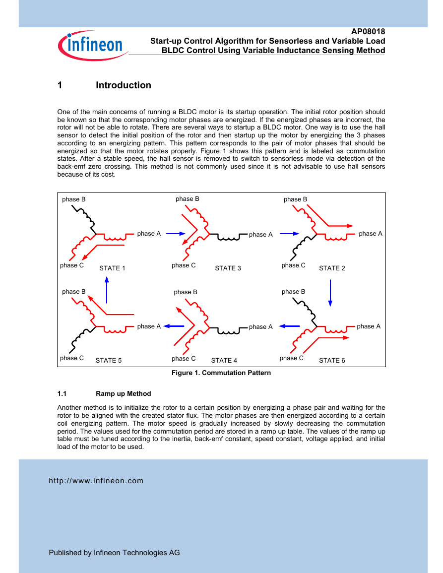
energized so that the motor rotates properly. Figure 1 shows this pattern and is labeled as commutation
states. After a stable speed, the hall sensor is removed to switch to sensorless mode via detection of the
back-emf zero crossing. This method is not commonly used since it is not advisable to use hall sensors
because of its cost.
phase B
phase B
phase B
phase A
phase A
phase A
phase C
STATE 1
phase C
STATE 3
phase C
STATE 2
phase B
phase B
phase B
phase A
phase A
phase A
phase C
STATE 5
phase C
STATE 4
phase C
STATE 6
Figure 1. Commutation Pattern
1.1
Ramp up Method
Another method is to initialize the rotor to a certain position by energizing a phase pair and waiting for the
rotor to be aligned with the created stator flux. The motor phases are then energized according to a certain
coil energizing pattern. The motor speed is gradually increased by slowly decreasing the commutation
period. The values used for the commutation period are stored in a ramp up table. The values of the ramp up
table must be tuned according to the inertia, back-emf constant, speed constant, voltage applied, and initial
load of the motor to be used.
http://www.infineon.com
Published by Infineon Technologies AG
�
AP08018
Start-up Control Algorithm for Sensorless and Variable Load
BLDC Control Using Variable Inductance Sensing Method
When the motor has reached the speed where the back-emf can be detected, the operation will switch to
sensorless mode via detection of back-emf zero crossing. The commutation period will now depend on the
time between the zero crossings. Although hall sensors are not required for this method of startup, the use of
ramp up table makes it ineffective since a change in the motor characteristics, like the initial load, will hinder
the motor from starting up correctly. A motor with different characteristics will not start properly using the
same values in the ramp table tuned for a different motor. The folder HOT5 Project 1 Demo 2 - Full
sensorless operation with ramp up contains all the source codes for the sensorless operation using ramp up
method.
Variable Inductance Sensing Method
2
A much more effective method uses variable inductance to detect the initial rotor position. It does not depend
on any motor specific characteristics, which allows it to work on any BLDC motor. Even changing the initial
load would not be a problem with this method. This method relies on the fact that if voltage is applied across
an inductor which is in the presence of a permanent magnet, the resulting current will either add or subtract
to the external field created by the permanent magnet, which leads to a further decrease or increase in the
inductance. In the case of a BLDC motor, the inductor is the stator while the permanent magnet is the rotor.
The implementation of this method requires that a voltage is applied for a fixed time such that it creates a
magnetic field in the direction of only one winding. Two magnetic fields of opposite directions should be
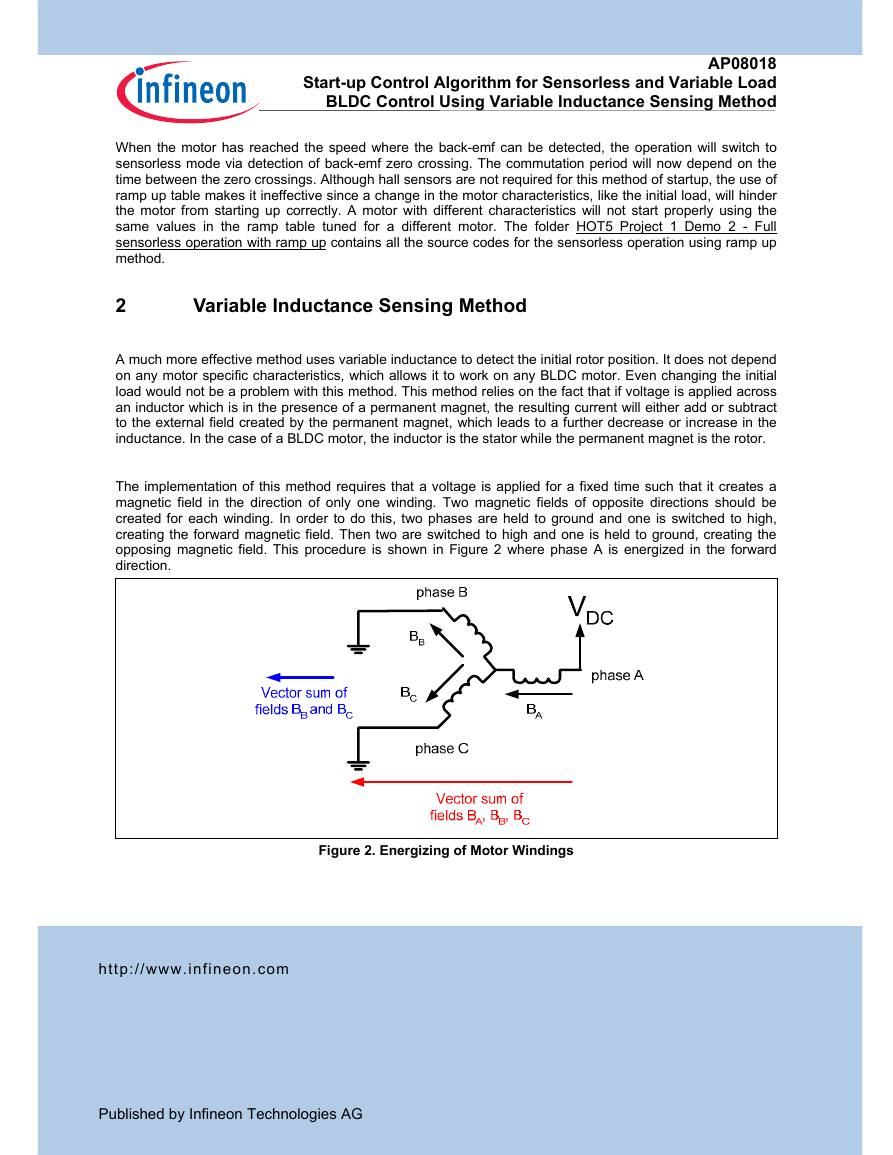
created for each winding. In order to do this, two phases are held to ground and one is switched to high,
creating the forward magnetic field. Then two are switched to high and one is held to ground, creating the
opposing magnetic field. This procedure is shown in Figure 2 where phase A is energized in the forward
direction.
Figure 2. Energizing of Motor Windings
http://www.infineon.com
Published by Infineon Technologies AG
�
AP08018
Start-up Control Algorithm for Sensorless and Variable Load
BLDC Control Using Variable Inductance Sensing Method
The two peak currents created from the two opposing magnetic fields are then measured and compared. The
larger peak will indicate the current that is in the same direction as the magnetic field caused by the
permanent magnet (rotor). Therefore, the polarity of the permanent magnet can be obtained, i.e. the rotor
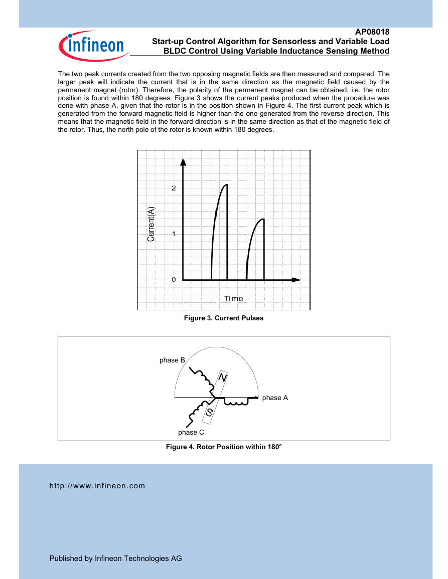
position is found within 180 degrees. Figure 3 shows the current peaks produced when the procedure was
done with phase A, given that the rotor is in the position shown in Figure 4. The first current peak which is
generated from the forward magnetic field is higher than the one generated from the reverse direction. This
means that the magnetic field in the forward direction is in the same direction as that of the magnetic field of
the rotor. Thus, the north pole of the rotor is known within 180 degrees.
Figure 3. Current Pulses
phase B
phase A
phase C
Figure 4. Rotor Position within 180°
http://www.infineon.com
Published by Infineon Technologies AG
�
AP08018
Start-up Control Algorithm for Sensorless and Variable Load
BLDC Control Using Variable Inductance Sensing Method
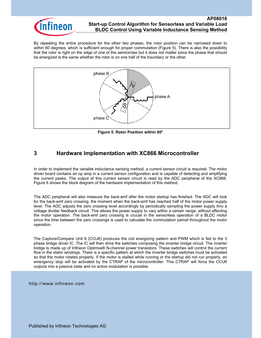
By repeating the entire procedure for the other two phases, the rotor position can be narrowed down to
within 60 degrees, which is sufficient enough for proper commutation (Figure 5). There is also the possibility
that the rotor is right on the edge of one of the semicircles but it does not matter since the phase that should
be energized is the same whether the rotor is on one half of the boundary or the other.
Figure 5. Rotor Position within 60°
Hardware Implementation with XC866 Microcontroller
3
In order to implement the variable inductance sensing method, a current sensor circuit is required. The motor
driver board contains an op amp in a current sensor configuration and is capable of detecting and amplifying
the current peaks. The output of this current sensor circuit is read by the ADC peripheral of the XC866.
Figure 6 shows the block diagram of the hardware implementation of this method.
The ADC peripheral will also measure the back-emf after the motor startup has finished. The ADC will look
for the back-emf zero crossing, the moment when the back-emf has reached half of the motor power supply
level. The ADC adjusts the zero crossing level accordingly by periodically sampling the power supply thru a
voltage divider feedback circuit. This allows the power supply to vary within a certain range, without affecting
the motor operation. The back-emf zero crossing is crucial in the sensorless operation of a BLDC motor
since the time between the zero crossings is used to calculate the commutation period throughout the motor
operation.
The Capture/Compare Unit 6 (CCU6) produces the coil energizing pattern and PWM which is fed to the 3
phase bridge driver IC. The IC will then drive the switches composing the inverter bridge circuit. The inverter
bridge is made up of Infineon Optimos® N-channel power transistors. These switches will control the current
flow in the stator windings. There is a specific pattern at which the inverter bridge switches must be activated
so that the motor rotates properly. If the motor is stalled while running or the startup did not run properly, an
emergency stop will be activated by the CTRAP of the microcontroller. This CTRAP will force the CCU6
outputs into a passive state and no active modulation is possible.
http://www.infineon.com
Published by Infineon Technologies AG
�





 2023年江西萍乡中考道德与法治真题及答案.doc
 2012年重庆南川中考生物真题及答案.doc
 2013年江西师范大学地理学综合及文艺理论基础考研真题.doc
 2020年四川甘孜小升初语文真题及答案I卷.doc
 2020年注册岩土工程师专业基础考试真题及答案.doc
 2023-2024学年福建省厦门市九年级上学期数学月考试题及答案.doc
 2021-2022学年辽宁省沈阳市大东区九年级上学期语文期末试题及答案.doc
 2022-2023学年北京东城区初三第一学期物理期末试卷及答案.doc
 2018上半年江西教师资格初中地理学科知识与教学能力真题及答案.doc
 2012年河北国家公务员申论考试真题及答案-省级.doc
 2020-2021学年江苏省扬州市江都区邵樊片九年级上学期数学第一次质量检测试题及答案.doc
 2022下半年黑龙江教师资格证中学综合素质真题及答案.doc