logo资料库

CDHD_EtherCAT_CANopen_fw1.41.x_Rev.6.4.pdf

第1页 / 共470页
第2页 / 共470页
第3页 / 共470页
第4页 / 共470页
第5页 / 共470页
第6页 / 共470页
第7页 / 共470页
第8页 / 共470页
资料共470页,剩余部分请下载后查看
Cover
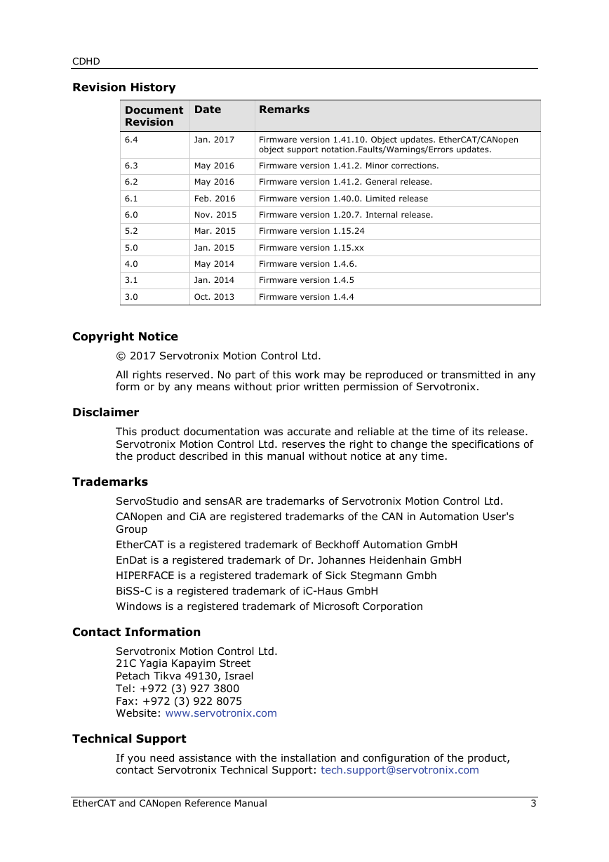
Revision History
Copyright Notice
Disclaimer
Trademarks
Contact Information
Technical Support
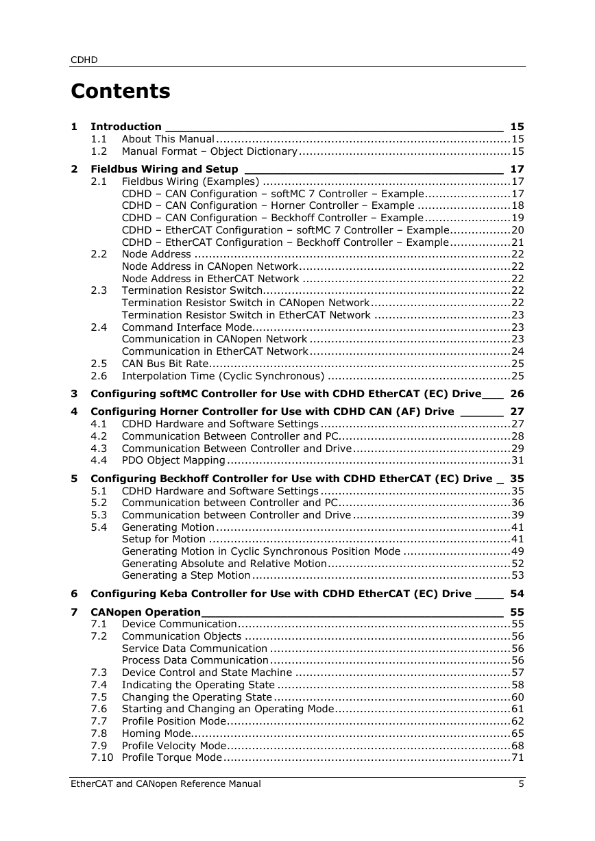
Contents
1 Introduction
1.1 About This Manual
1.2 Manual Format – Object Dictionary
2 Fieldbus Wiring and Setup
2.1 Fieldbus Wiring (Examples)
CDHD – CAN Configuration – softMC 7 Controller – Example
CDHD – CAN Configuration – Horner Controller – Example
CDHD – CAN Configuration – Beckhoff Controller – Example
CDHD – EtherCAT Configuration – softMC 7 Controller – Example
CDHD – EtherCAT Configuration – Beckhoff Controller – Example
2.2 Node Address
Node Address in CANopen Network
Node Address in EtherCAT Network
2.3 Termination Resistor Switch
Termination Resistor Switch in CANopen Network
Termination Resistor Switch in EtherCAT Network
2.4 Command Interface Mode
Communication in CANopen Network
Communication in EtherCAT Network
2.5 CAN Bus Bit Rate
2.6 Interpolation Time (Cyclic Synchronous)
3 Configuring softMC Controller for Use with CDHD EtherCAT (EC) Drive
4 Configuring Horner Controller for Use with CDHD CAN (AF) Drive
4.1 CDHD Hardware and Software Settings
4.2 Communication Between Controller and PC
4.3 Communication Between Controller and Drive
4.4 PDO Object Mapping
5 Configuring Beckhoff Controller for Use with CDHD EtherCAT (EC) Drive
5.1 CDHD Hardware and Software Settings
5.2 Communication between Controller and PC
5.3 Communication between Controller and Drive
5.4 Generating Motion
Setup for Motion
Generating Motion in Cyclic Synchronous Position Mode
Generating Absolute and Relative Motion
Generating a Step Motion
6 Configuring Keba Controller for Use with CDHD EtherCAT (EC) Drive
7 CANopen Operation
7.1 Device Communication
7.2 Communication Objects
Service Data Communication
Process Data Communication
7.3 Device Control and State Machine
7.4 Indicating the Operating State
7.5 Changing the Operating State
7.6 Starting and Changing an Operating Mode
7.7 Profile Position Mode
Example: Profile Position
7.8 Homing Mode
Example: Homing
7.9 Profile Velocity Mode
Example: Profile Velocity
7.10 Profile Torque Mode
Example: Profile Torque
7.11 Interpolated Position Mode
Example: Interpolated Position Profile
7.12 Cyclic Synchronous Position Mode
Example: Cyclic Synchronous Position Profile
7.13 Cyclic Synchronous Velocity Mode
Example: Cyclic Synchronous Velocity
7.14 Cyclic Synchronous Torque Mode
Example: Cyclic Synchronous Torque
7.15 Digital Output Operation
8 Units
8.1 Units Overview
8.2 Position Units
Position Resolution - Examples
8.3 Velocity Units
8.4 Acceleration/Deceleration Units
8.5 Current Units
8.6 Torque Units
8.7 Setting Units - Examples
Rotary Motor
Setting Units to Represent Revolutions
Setting Units to Represent Degrees
Setting Units to Represent Feedback Counts
Linear Motor
Setting Units to Represent Motor Pitch
Setting Units to Represent Millimeters
Setting Units to Represent Feedback Counts
9 Communication Objects
1000h – Device Type
1001h – Error Register
1002h – Manufacturer Status Register
1003h – Predefined Error Field
1005h – COBID SYNC Message
1006h – Communication Cycle Period
1007h – Synchronous Window Length
1008h – Manufacturer Device Name
1009h – Manufacturer Hardware Version
100Ah – Manufacturer Software Version
100Ch – Guard Time
100Dh – Lifetime Factor
1010h – Store Parameters
1011h – Restore Default Parameters
1014h – COBID EMCY
1015h – Inhibit Time Emergency
1016h – Heartbeat Consumer Time
1017h – Producer Heartbeat Time
1018h – Identity Object
1019h – Synchronous Counter Overflow Value
1029h – Error Behavior
1200h – Server SDO Parameter 1
1201h – Server SDO Parameter 2
1400h – Receive PDO Communication Parameter 1
1401h – Receive PDO Communication Parameter 2
1402h – Receive PDO Communication Parameter 3
1403h – Receive PDO Communication Parameter 4
1600h – Receive PDO Mapping Parameter 1
1601h – Receive PDO Mapping Parameter 2
1602h – Receive PDO Mapping Parameter 3
1603h – Receive PDO Mapping Parameter 4
1800h – Transmit PDO Communication Parameter 1
1801h – Transmit PDO Communication Parameter 2
1802h – Transmit PDO Communication Parameter 3
1803h – Transmit PDO Communication Parameter 4
1A00h – Transmit PDO Mapping Parameter 1
1A01h – Transmit PDO Mapping Parameter 2
1A02h – Transmit PDO Mapping Parameter 3
1A03h – Transmit PDO Mapping Parameter 4
1C00h – Sync Manager Communication Type
1C10h – Sync Manager 0 PDO Assignment
1C11h – Sync Manager 1 PDO Assignment
1C12h – Sync Manager 2 PDO Assignment
1C13h – Sync Manager 3 PDO Assignment
10 ManufacturerSpecific Objects
2002h – Configuration Command
2003h – Current BEMF Compensation Gain
2006h – Current Integral (KI) Gain
2007h – Current Proportional (KP) Gain
200Ah – HD AntiVibration Filter
200Bh – HD AntiResonance Sharpness
200Ch – HD AntiVibration Gain
200Dh – Absolute Feedback Offset
200Eh – Auto Home Mode
200Fh – Fieldbus Unit Scaling
2010h – Velocity Loop Bandwidth
2011h – Warning Bits
2013h – Current CL VD
2014h – Current CL VQ
2015h – Drive Name
2016h – Electrical Position
2017h – HD Derivative Gain
2018h – HD Integral Gain
2019h – HD DerivativeIntegral Gain
201Ah – HD Proportional Gain
201Bh – HD Adaptive Gain Scale Factor
201Ch – Position Acceleration Feedforward to Current
201Dh – Position Acceleration Feedforward
201Eh – Position Derivative (KD) Gain
201Fh – Position Proportional Adaptive Gain
2020h – Position Integral (KI) Gain
2021h – Position Integral Output Saturation
2022h – Position Proportional (KP) Gain
2023h – Position Velocity Feedforward
2024h – Motor Type
2025h – Velocity Feedforward Ratio
2026h – Velocity Integrator
2027h – Velocity Gain
2028h – Mechanical Angle
2029h – Encoder Type
202Ah – Motor Encoder Index Position
202Bh – Motor and Feedback Direction
202Ch – Point-to-Point Move Low Pass Filter
202Dh – Motor Feedback Mode
202Eh – Motor Foldback Status
202Fh – Motor Foldback Delay Time
2030h – Motor Foldback Disable
2031h – Motor Foldback Recovery Time
2032h – Motor Foldback Time Constant
2033h – Motor Foldback Current
2034h – Motor Foldback Fault Threshold
2035h – Motor Foldback Warning Threshold
2036h – Motor Peak Current
2037h – Rotor Inertia
2038h – Torque Constant for Linear Motors
2039h – Torque Constant
203Ah – Motor Inductance
203Bh – Adaptive Gain Value at Continuous Motor Current
203Ch – Adaptive Gain Value at Peak Motor Current
203Dh – Rotor Coil Mass (Linear Motor)
203Eh – Motor Commutation Type
203Fh – Motor Name
2040h – Phase Disconnect Scan
2041h – Motor Setup
2042h – Motor Setup Status
2043h – Commutation Offset
2044h – Drive Temperature
2045h – Feedback Direction
2046h – Disabling Mode
2047h – Deceleration Distance
2048h – Deceleration Distance 2
2049h – Quick Stop Deceleration Time
204Ah – Active Disabling Speed Threshold
204Bh – Active Disabling Time
204Ch – Factory Restore
204Dh – Feedback Type
204Eh – Velocity Loop Output Filter Parameter 1
204Fh – Velocity Loop Output Filter Parameter 2
2050h – Velocity Loop Output Filter Mode
2051h – Foldback Status
2052h – Friction Compensation Negative Current
2053h – Friction Compensation Positive Current
2054h – Friction Compensation Negative Velocity Hysteresis
2055h – Friction Compensation Positive Velocity Hysteresis
2056h – Halls State
2057h – Invert Hall Signals
2058h – Hall Signals Type
205Ah – Harmonic Correction Feedback Parameter 1
205Bh – Harmonic Correction Feedback Parameter 2
205Dh – Harmonic Current ICMD Parameter 1
205Eh – Harmonic Current ICMD Parameter 2
2060h – HD Current Filter Damping
2061h – HD Current Notch Filter Center
2062h – HD Current Notch Filter Bandwidth
2063h – Hold Position Command
2064h – Hardware Position External
2065h – Hardware Position
2066h – Current D Axis
2067h – Current Q Axis
2068h – Current Feedforward LPF
2069h – Drive Foldback Current Limit
206Ah – Drive Foldback Fault Threshold
206Bh – Drive Foldback Warning Threshold
206Ch – Gravity Compensation
206Fh – Encoder Index Position Feedback
2070h – Input Inversion
2071h – Dynamic Brake Current
2072h – Phase U Actual Current
2073h – Phase U Current Offset
2074h – Phase V Actual Current
2075h – Phase V Current Offset
2076h – Zero Procedure Current
2077h – Position Integral Input Saturation
2078h – Negative Limit Switch Status
2079h – Positive Limit Switch Status
207Ah – Load to Motor Inertia Ratio
207Bh – Drive Peak Current
207Ch – Drive Continuous Current
207Dh – Motor Pitch
207Eh – Motor Poles
207Fh – Motor Resistance
2080h – Motor Resolver Poles
2081h – Motor Rated Torque
2082h – Current KCFF Gain
2083h – Torque Commutation Angle Advance at Motor Continuous Current
2084h – Torque Commutation Angle Advance at Motor Peak Current
2085h – Velocity Commutation Angle Advance at Motor Maximum Speed
2086h – Velocity Commutation Angle Advance at Motor Maximum Speed/2
2087h – HD Spring Filter
2088h – PFB Backup
2089h – PFB Backup Mode
208Ah – HD Maximum Adaptive Gain
208Bh – HD Current Filter – Second Notch Filter Bandwidth
208Ch – HD Current Filter – Second Notch Filter Center
208Dh – Emergency or Controlled Stop Current Limit
208Eh – Position Command
208Fh – HD Flexibility Compensation
2090h – Home Status
2091h – HD Spring Deceleration Ratio
2095h – Position Feedback Offset
2096h – HD Anti Vibration Filter
2097h – HD Anti Vibration Filter 2
2099h – Current Level 1 for Digital Output Definition
209Ah – Current Level 2 for Digital Output Definition
209Bh – Output Inversion
209Ch – Output Mode
209Dh – Position Level 1 for Digital Output Definition
209Eh – Position Level 2 for Digital Output Definition
209Fh – Velocity Level 1 for Digital Output Definition
20A0h – Velocity Level 2 for Digital Output Definition
20A1h – OverVoltage Threshold
20A2h – Software Enable Status
20A3h – Position Loop Position Error
20A4h – Phase Find Command
20A5h – Forced Electrical Position
20A6h – Phase Find Gain
20A7h – Phase Find Current
20A8h – Phase Find Mode
20A9h – Phase Find Status
20AAh – Phase Find Duration
20ABh – Position Loop Controller Mode
20ACh – Software Position Limit Mode
20ADh – PRB Generator Frequency
20AEh – PRB Generator Mode
20AFh – PRB Generator Configuration
20B0h – PTP Generator Target Error
20B1h – PTP Generator Velocity Command
20B2h – PWM Frequency
20B3h – Gear Mode
20B5h – Position Error in Position Flag
20B6h – Machine Hardware Position External (DSP)
20B8h – Fault Relay Status
20B9h – Fault Relay Mode
20BAh – Remote Hardware Enable Status
20BBh – Resolver Amplitude Range
20BCh – Resolver Conversion Bandwidth
20BDh – Save/Load Status
20BEh – Sine/Cosine Calibration Command
20BFh – Sine/Cosine Calibration Mode
20C0h – Sine/Cosine Calibration Status
20C1h – Sine/Cosine Calibration Parameters
20C2h – Synchronization Mode
20C3h – Tracking Factor
20C4h – Motor OverTemperature
20C5h – Motor OverTemperature Clear Fault Level
20C6h – Motor OverTemperature Mode
20C7h – Motor Temperature
20C8h – Motor OverTemperature Time
20C9h – Motor OverTemperature Fault Level
20CAh – Motor OverTemperature Type
20CBh – Tamagawa MultiTurn Reset
20CCh – Run Time
20CDh – UnderVoltage Mode
20CEh – UnderVoltage Recovery Mode
20CFh – UnderVoltage Threshold
20D0h – UnderVoltage Time
20D1h – Bus Voltage (DC)
20D3h – Velocity Error
20D4h – Velocity Loop Controller
20D5h – Velocity Design Structure
20D6h – Velocity Filter Mode
20D7h – Drive Version
20D8h – Velocity Loop Output Filter
20D9h – Velocity Loop Input Filter
20DAh – Advanced Pole Placement H Polynomial
20DBh – Advanced Pole Placement R Polynomial
20DCh – Wake No Shake Status
20DDh – Display Warnings
20DEh – External Encoder Resolution
20DFh – Zeroing Command
20E0h – Input Mode
20E1h – Rotary Address Switch
20E2h – Test 7Segment Display
20E3h – Encoder Simulation Mode
20E4h – Encoder Simulation Resolution
20E5h – Encoder Simulation Index Position
20E6h – Record Done Indicator
20E7h – Get Recorded Data
20E8h – Trigger Recording
20E9h – Stop Recording
20EAh – Record
20EBh – Recording Status
20ECh – Ready to Record
20EEh – Drive and Motor Maximum Velocity
20EFh – Dead Time Compensation Minimal Level
20F0h – Drive and Motor Maximum Current
20F2h – Analog Input 1
20F3h – Analog Input 1 Deadband
20F4h – Analog Input 1 Current Scaling
20F5h – Analog Input 1 Low Pass Filter
20F6h – Analog Input 1 Offset
20F7h – Analog Input 1 Velocity Scaling
20F8h – Analog Input 1 Zeroing
20F9h – Analog Input 2
20FAh – Analog Input 2 Deadband
20FBh – Analog Input 2 Current Scaling
20FCh – Analog Input 2 Low Pass Filter
20FDh – Analog Input 2 Offset
20FFh – Analog Input 2 Zeroing
2100h – Analog Input 2 Mode
2103h – Homing Command
2104h – Current Level for Homing on Hard Stop
2106h – Current Loop Compatibility Mode
2108h – Point-to-Point Move Average
2109h – Point-to-Point Move Smoothing Mode
210Bh – Load to Motor Inertia Ratio for Anti-Vibration Only
210Ch – HD Anti-Resonance Filter Divider
210Dh – HD Current Filter Low Pass Filter Rise Time
2113h – Drive Ready
2114h – Drive Status
2115h – Step Command
2116h – Position Motion Ended
2117h – Units Linear Acc/Dec
2118h – Units Linear Position
2119h – Units Linear Velocity
211Ah – Units Rotary Acc/Dec
211Bh – Units Rotary Position
211Ch – Units Rotary Velocity
211Dh – Velocity Filter Pole Frequency
211Eh – Gear
2120h – Gear Acceleration Threshold
2121h – Gear Filter Acceleration Feedforward
2122h – Gear Filter Mode
2123h – Gear Filter Depth
2124h – Gear Filter Velocity and Acceleration Depth
2125h – Gear Filter Velocity Feedforward
2126h – Gear Ratio Multiplier
2127h – Gearing Input Interpolation Mode
2128h – Gear Following Limits Mode
2129h – Gear Ratio Divider
212Ah – Drive Info
212Bh – Torque Window
212Ch – Block Control Word
212Dh – HD Anti-Vibration Sharpness2
212Eh – HD KIDV Gain
212Fh – HD KPI Gain
2130h – Torque Slope Enable
2131h – Touch Probe Event Counter
2133h – Analog Output
2134h – Analog Output Command
2135h – Analog Output Current Scaling
2136h – Analog Output Limit
2137h – Analog Output Mode
2138h – Analog Output Velocity Scaling
2139h – Secondary Feedback Mode
213Ah – Secondary Feedback Type
213Bh – Secondary Feedback Scaling Numerator
213Ch – Secondary Feedback Scaling Denominator
213Dh – Secondary Feedback Unit Numerator
213Eh – Secondary Feedback Unit Denominator
213Fh – Secondary Feedback Offset
2140h – Secondary Feedback Position Actual Value
2141h – Secondary Feedback Velocity Actual Value
2142h – Primary Position Actual Value
2143h – Primary Velocity Actual Value
2144h – Secondary Feedback Position Error Max
2145h – Secondary Feedback Position Error Threshold
2146h – Secondary Feedback Position Error Time
2147h – Probe Data Rise
2148h – Probe Data Fall
2149h – Probe Variable Select
214Ah – Software Position Limit Hysteresis Value
214Bh – Probe Level Period
214Ch – SensAR Info
214Eh – Modulo Mode
214Fh – Modulo Limits
2150h – Counts Per Revolution
2151h – Start SFB Voltage Correction Calibration
2152h – SFB Voltage Correct Number of Sectors
2153h – SFB Slow Movement Lower Voltage
2154h – SFB Slow Movement Upper Voltage
2155h – Voltage Correction Number of Sectors for Analog Input 2
2156h – Voltage Correction Result for Analog Input 2
2157h – SFB Manual Calibration Process Activation
2158h – Digital Outputs After Fault
2159h – Heartbeat Tolerance
215Ah – Sankyo Multi-Turn Reset
215Bh – Voltage State
215Ch – Voltage Non-Volatile State
215Dh – Voltage Backlash Position
215Eh – Voltage Correction Current Limit
215Fh – Voltage Fast Speed
2160h – Voltage Slow Speed
2161h – Secondary Feedback Position Actual Value - User Units
2162h – Secondary Feedback Offset - User Units
2163h – Secondary Feedback Position Error Max - User Units
2164h – Secondary Feedback Position Error Threshold - User Units
2165h – Secondary Feedback Position Command - User Units
2166h – Secondary Feedback Position Error - User Units
2167h – Secondary Feedback Voltage Dwell Time
2168h – Secondary Feedback Position Error
2169h – Voltage Correction Array
216Ah – Voltage Correction Array 2
216Bh – Probe 2 Level Period for Stabilization
216Ch – CANopen Manufacturer-Specific SDO Abort Code
216Dh – Analog Input 2 User Command
216Eh – Analog Input 2 User Denominator
216Fh – Analog Input 2 User Numerator
2170h – Analog Input 2 User Offset
2171h – Secondary Feedback Voltage Correction 1
2172h – Secondary Feedback Voltage Correction 2
2173h – Motor Pitch High Resolution
2176h – BiSS-C Fields
2179h – Halls Only Communication
217Ah – Debug Position Command
217Bh – Zero Motor Phase Degree
217Ch – Reference Offset Value
217Dh – Hardware Version
217Eh – Machine Hardware Position External (FPGA)
11 Standard Servo Drive Objects
603Fh – Error Code
6040h – Controlword
6041h – Statusword
605Bh – Shutdown Option Code
605Ch – Disable Operation Option Code
605Dh – Halt Option Code
605Eh – Fault Reaction Option Code
6060h – Modes of Operation
6061h – Modes of Operation Display
6062h – Position Demand Value
6063h – Position Actual Internal Value
6064h – Position Actual Value
6065h – Following Error Window
6066h – Following Error Time Out
6067h – Position Window
6068h – Position Window Time
606Bh – Velocity Demand Value
606Ch – Velocity Actual Value
606Dh – Velocity Window
606Eh – Velocity Window Time
606Fh – Velocity Threshold
6070h – Velocity Threshold Time
6071h – Target Torque
6073h – Maximum Current
6074h – Torque Demand Value
6075h – Motor Rated Current
6076h – Motor Rated Torque
6077h – Torque Actual Value
6078h – Current Actual Value
6079h – DC Link Circuit Voltage
607Ah – Target Position
607Ch – Home Offset
607Dh – Software Position Limit
607Eh – Polarity
607Fh – Max Profile Velocity
6080h – Max Motor Speed
6081h – Profile Velocity in Profile Position Mode
6083h – Profile Acceleration
6084h – Profile Deceleration
6085h – Quick Stop Deceleration
6087h – Torque Slope
608Fh – Position Encoder Resolution
6091h – Gear Ratio
6092h – Feed Constant
6098h – Homing Mode
6099h – Homing Speeds
609Ah – Homing Acceleration
60B0h – Position Offset
60B1h – Velocity Offset
60B2h – Torque Offset
60B8h – Touch Probe Function
60B9h – Touch Probe Status
60BAh – Touch Probe 1 Position Positive Edge
60BBh – Touch Probe 1 Position Negative Edge
60BCh – Touch Probe 2 Position Positive Edge
60BDh – Touch Probe 2 Position Negative Edge
60C0h – Interpolation Submode
60C1h – Interpolation Data Record
60C2h – Interpolation Time Period
60C4h – Interpolation Data Configuration
60C5h – Max Acceleration
60C6h – Max Deceleration
60D5h – Touch Probe 1 Positive Edge Counter
60D6h – Touch Probe 1 Negative Edge Counter
60D7h – Touch Probe 2 Positive Edge Counter
60D8h – Touch Probe 2 Negative Edge Counter
60F2h – Positioning Option Code
60F4h – Following Error Actual Value
60FCh – Position Demand Internal Value
60FDh – Digital Inputs
60FEh – Digital Outputs
60FFh – Target Velocity
6502h – Supported Drive Modes
12 CANopen and EtherCAT Troubleshooting
12.1 Warning Codes
12.2 Error and Fault Codes
Service Request Error (Abort) Codes
Emergency Error (Fault) Codes
12.3 Common Communication Problems
b1 – PLL synchronization failed
C1 – CANopen cable disconnected, heartbeat lost
Fb1 – Fieldbus – Target position exceeds velocity limit
Fb3 – EtherCAT cable disconnected
Fb4 – Fieldbus target command lost
EtherCAT and CANopen Reference Manual CDHD Servo Drive AF | EC | EB Models Revision: 6.4 Firmware Version: 1.41.x
CDHD Revision History Document Revision 6.4 6.3 6.2 6.1 6.0 5.2 5.0 4.0 3.1 3.0 Date Jan. 2017 May 2016 May 2016 Feb. 2016 Nov. 2015 Mar. 2015 Jan. 2015 May 2014 Jan. 2014 Oct. 2013 Remarks Firmware version 1.41.10. Object updates. EtherCAT/CANopen object support notation.Faults/Warnings/Errors updates. Firmware version 1.41.2. Minor corrections. Firmware version 1.41.2. General release. Firmware version 1.40.0. Limited release Firmware version 1.20.7. Internal release. Firmware version 1.15.24 Firmware version 1.15.xx Firmware version 1.4.6. Firmware version 1.4.5 Firmware version 1.4.4 Copyright Notice © 2017 Servotronix Motion Control Ltd. All rights reserved. No part of this work may be reproduced or transmitted in any form or by any means without prior written permission of Servotronix. Disclaimer This product documentation was accurate and reliable at the time of its release. Servotronix Motion Control Ltd. reserves the right to change the specifications of the product described in this manual without notice at any time. Trademarks ServoStudio and sensAR are trademarks of Servotronix Motion Control Ltd. CANopen and CiA are registered trademarks of the CAN in Automation User's Group EtherCAT is a registered trademark of Beckhoff Automation GmbH EnDat is a registered trademark of Dr. Johannes Heidenhain GmbH HIPERFACE is a registered trademark of Sick Stegmann Gmbh BiSS-C is a registered trademark of iC-Haus GmbH Windows is a registered trademark of Microsoft Corporation Contact Information Servotronix Motion Control Ltd. 21C Yagia Kapayim Street Petach Tikva 49130, Israel Tel: +972 (3) 927 3800 Fax: +972 (3) 922 8075 Website: www.servotronix.com Technical Support If you need assistance with the installation and configuration of the product, contact Servotronix Technical Support: tech.support@servotronix.com EtherCAT and CANopen Reference Manual 3
CDHD 4 EtherCAT and CANopen Reference Manual
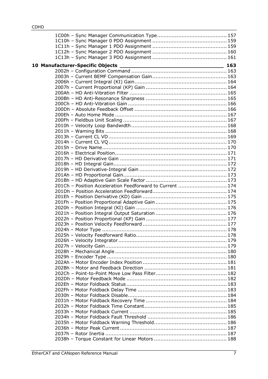
CDHD Contents 2.1 1 Introduction _______________________________________________ 15 1.1 About This Manual .................................................................................. 15 1.2 Manual Format – Object Dictionary ........................................................... 15 2 Fieldbus Wiring and Setup ____________________________________ 17 Fieldbus Wiring (Examples) ..................................................................... 17 CDHD – CAN Configuration – softMC 7 Controller – Example ........................ 17 CDHD – CAN Configuration – Horner Controller – Example .......................... 18 CDHD – CAN Configuration – Beckhoff Controller – Example ........................ 19 CDHD – EtherCAT Configuration – softMC 7 Controller – Example ................. 20 CDHD – EtherCAT Configuration – Beckhoff Controller – Example ................. 21 2.2 Node Address ........................................................................................ 22 Node Address in CANopen Network ........................................................... 22 Node Address in EtherCAT Network .......................................................... 22 2.3 Termination Resistor Switch..................................................................... 22 Termination Resistor Switch in CANopen Network ....................................... 22 Termination Resistor Switch in EtherCAT Network ...................................... 23 2.4 Command Interface Mode........................................................................ 23 Communication in CANopen Network ........................................................ 23 Communication in EtherCAT Network ........................................................ 24 2.5 CAN Bus Bit Rate .................................................................................... 25 2.6 Interpolation Time (Cyclic Synchronous) ................................................... 25 3 Configuring softMC Controller for Use with CDHD EtherCAT (EC) Drive ___ 26 4 Configuring Horner Controller for Use with CDHD CAN (AF) Drive ______ 27 4.1 CDHD Hardware and Software Settings ..................................................... 27 4.2 Communication Between Controller and PC ................................................ 28 4.3 Communication Between Controller and Drive ............................................ 29 4.4 PDO Object Mapping ............................................................................... 31 5 Configuring Beckhoff Controller for Use with CDHD EtherCAT (EC) Drive _ 35 5.1 CDHD Hardware and Software Settings ..................................................... 35 5.2 Communication between Controller and PC ................................................ 36 5.3 Communication between Controller and Drive ............................................ 39 5.4 Generating Motion .................................................................................. 41 Setup for Motion .................................................................................... 41 Generating Motion in Cyclic Synchronous Position Mode .............................. 49 Generating Absolute and Relative Motion ................................................... 52 Generating a Step Motion ........................................................................ 53 6 Configuring Keba Controller for Use with CDHD EtherCAT (EC) Drive ____ 54 7 CANopen Operation __________________________________________ 55 7.1 Device Communication ............................................................................ 55 7.2 Communication Objects .......................................................................... 56 Service Data Communication ................................................................... 56 Process Data Communication ................................................................... 56 7.3 Device Control and State Machine ............................................................ 57 7.4 Indicating the Operating State ................................................................. 58 7.5 Changing the Operating State .................................................................. 60 7.6 Starting and Changing an Operating Mode ................................................. 61 7.7 Profile Position Mode ............................................................................... 62 7.8 Homing Mode......................................................................................... 65 7.9 Profile Velocity Mode ............................................................................... 68 7.10 Profile Torque Mode ................................................................................ 71 EtherCAT and CANopen Reference Manual 5
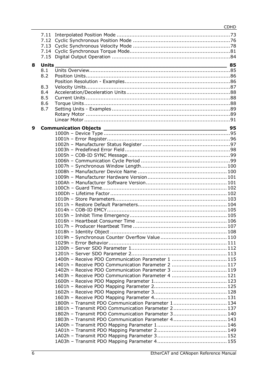
CDHD 7.11 Interpolated Position Mode ...................................................................... 73 7.12 Cyclic Synchronous Position Mode ............................................................ 76 7.13 Cyclic Synchronous Velocity Mode ............................................................ 78 7.14 Cyclic Synchronous Torque Mode .............................................................. 81 7.15 Digital Output Operation ......................................................................... 84 8 Units _____________________________________________________ 85 8.1 Units Overview ....................................................................................... 85 Position Units ......................................................................................... 86 8.2 Position Resolution - Examples ................................................................. 86 8.3 Velocity Units ......................................................................................... 87 8.4 Acceleration/Deceleration Units ................................................................ 88 8.5 Current Units ......................................................................................... 88 8.6 Torque Units .......................................................................................... 88 8.7 Setting Units - Examples ......................................................................... 89 Rotary Motor ......................................................................................... 89 Linear Motor .......................................................................................... 91 9 Communication Objects ______________________________________ 95 1000h – Device Type .............................................................................. 95 1001h – Error Register ............................................................................ 96 1002h – Manufacturer Status Register ...................................................... 97 1003h – Predefined Error Field ................................................................. 98 1005h – COB-ID SYNC Message ............................................................... 99 1006h – Communication Cycle Period ....................................................... 99 1007h – Synchronous Window Length ..................................................... 100 1008h – Manufacturer Device Name ....................................................... 100 1009h – Manufacturer Hardware Version ................................................. 101 100Ah – Manufacturer Software Version .................................................. 101 100Ch – Guard Time ............................................................................. 102 100Dh – Lifetime Factor ........................................................................ 102 1010h – Store Parameters ..................................................................... 103 1011h – Restore Default Parameters....................................................... 104 1014h – COB-ID EMCY .......................................................................... 105 1015h – Inhibit Time Emergency ............................................................ 105 1016h – Heartbeat Consumer Time ........................................................ 106 1017h – Producer Heartbeat Time .......................................................... 107 1018h – Identity Object ........................................................................ 108 1019h – Synchronous Counter Overflow Value ......................................... 110 1029h – Error Behavior ......................................................................... 111 1200h – Server SDO Parameter 1........................................................... 112 1201h – Server SDO Parameter 2........................................................... 113 1400h – Receive PDO Communication Parameter 1 .................................. 115 1401h – Receive PDO Communication Parameter 2 .................................. 117 1402h – Receive PDO Communication Parameter 3 .................................. 119 1403h – Receive PDO Communication Parameter 4 .................................. 121 1600h – Receive PDO Mapping Parameter 1............................................. 123 1601h – Receive PDO Mapping Parameter 2............................................. 125 1602h – Receive PDO Mapping Parameter 3............................................. 128 1603h – Receive PDO Mapping Parameter 4............................................. 131 1800h – Transmit PDO Communication Parameter 1 ................................. 134 1801h – Transmit PDO Communication Parameter 2 ................................. 137 1802h – Transmit PDO Communication Parameter 3 ................................. 140 1803h – Transmit PDO Communication Parameter 4 ................................. 143 1A00h – Transmit PDO Mapping Parameter 1 ........................................... 146 1A01h – Transmit PDO Mapping Parameter 2 ........................................... 149 1A02h – Transmit PDO Mapping Parameter 3 ........................................... 152 1A03h – Transmit PDO Mapping Parameter 4 ........................................... 155 6 EtherCAT and CANopen Reference Manual
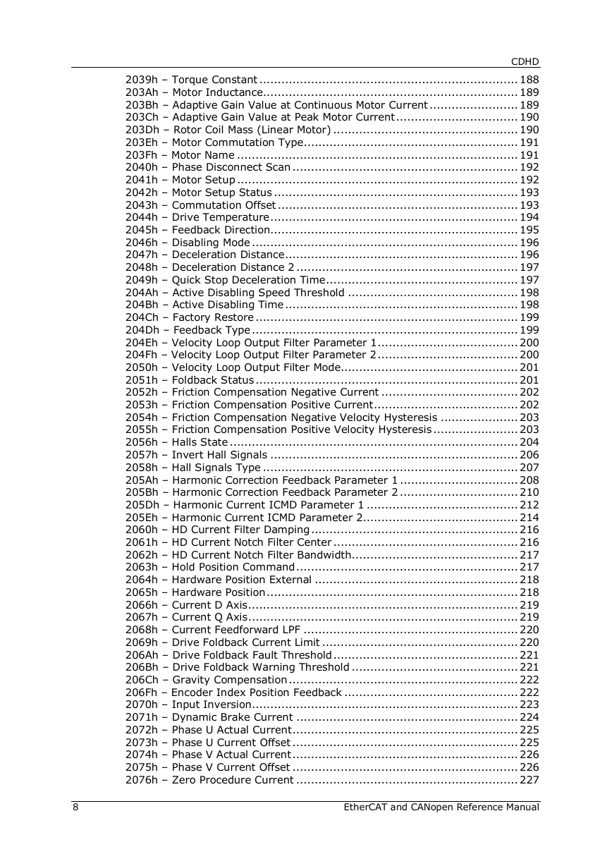
CDHD 1C00h – Sync Manager Communication Type ........................................... 157 1C10h – Sync Manager 0 PDO Assignment .............................................. 159 1C11h – Sync Manager 1 PDO Assignment .............................................. 159 1C12h – Sync Manager 2 PDO Assignment .............................................. 160 1C13h – Sync Manager 3 PDO Assignment .............................................. 161 10 Manufacturer-Specific Objects ________________________________ 163 2002h – Configuration Command ........................................................... 163 2003h – Current BEMF Compensation Gain .............................................. 163 2006h – Current Integral (KI) Gain ......................................................... 164 2007h – Current Proportional (KP) Gain .................................................. 164 200Ah – HD Anti-Vibration Filter ............................................................ 165 200Bh – HD Anti-Resonance Sharpness .................................................. 165 200Ch – HD Anti-Vibration Gain ............................................................. 166 200Dh – Absolute Feedback Offset ......................................................... 166 200Eh – Auto Home Mode ..................................................................... 167 200Fh – Fieldbus Unit Scaling ................................................................ 167 2010h – Velocity Loop Bandwidth ........................................................... 168 2011h – Warning Bits ........................................................................... 168 2013h – Current CL VD ......................................................................... 169 2014h – Current CL VQ ......................................................................... 170 2015h – Drive Name ............................................................................. 170 2016h – Electrical Position ..................................................................... 171 2017h – HD Derivative Gain .................................................................. 171 2018h – HD Integral Gain ...................................................................... 172 2019h – HD Derivative-Integral Gain ...................................................... 172 201Ah – HD Proportional Gain ................................................................ 173 201Bh – HD Adaptive Gain Scale Factor .................................................. 173 201Ch – Position Acceleration Feedforward to Current .............................. 174 201Dh – Position Acceleration Feedforward .............................................. 174 201Eh – Position Derivative (KD) Gain .................................................... 175 201Fh – Position Proportional Adaptive Gain ............................................ 175 2020h – Position Integral (KI) Gain ........................................................ 176 2021h – Position Integral Output Saturation ............................................ 176 2022h – Position Proportional (KP) Gain .................................................. 177 2023h – Position Velocity Feedforward .................................................... 177 2024h – Motor Type ............................................................................. 178 2025h – Velocity Feedforward Ratio ........................................................ 178 2026h – Velocity Integrator ................................................................... 179 2027h – Velocity Gain ........................................................................... 179 2028h – Mechanical Angle ..................................................................... 180 2029h – Encoder Type .......................................................................... 180 202Ah – Motor Encoder Index Position .................................................... 181 202Bh – Motor and Feedback Direction ................................................... 181 202Ch – Point-to-Point Move Low Pass Filter ............................................ 182 202Dh – Motor Feedback Mode .............................................................. 182 202Eh – Motor Foldback Status .............................................................. 183 202Fh – Motor Foldback Delay Time ....................................................... 183 2030h – Motor Foldback Disable ............................................................. 184 2031h – Motor Foldback Recovery Time .................................................. 184 2032h – Motor Foldback Time Constant ................................................... 185 2033h – Motor Foldback Current ............................................................ 185 2034h – Motor Foldback Fault Threshold ................................................. 186 2035h – Motor Foldback Warning Threshold ............................................. 186 2036h – Motor Peak Current .................................................................. 187 2037h – Rotor Inertia ........................................................................... 187 2038h – Torque Constant for Linear Motors ............................................. 188 EtherCAT and CANopen Reference Manual 7
CDHD 2039h – Torque Constant ...................................................................... 188 203Ah – Motor Inductance..................................................................... 189 203Bh – Adaptive Gain Value at Continuous Motor Current ........................ 189 203Ch – Adaptive Gain Value at Peak Motor Current ................................. 190 203Dh – Rotor Coil Mass (Linear Motor) .................................................. 190 203Eh – Motor Commutation Type .......................................................... 191 203Fh – Motor Name ............................................................................ 191 2040h – Phase Disconnect Scan ............................................................. 192 2041h – Motor Setup ............................................................................ 192 2042h – Motor Setup Status .................................................................. 193 2043h – Commutation Offset ................................................................. 193 2044h – Drive Temperature ................................................................... 194 2045h – Feedback Direction................................................................... 195 2046h – Disabling Mode ........................................................................ 196 2047h – Deceleration Distance ............................................................... 196 2048h – Deceleration Distance 2 ............................................................ 197 2049h – Quick Stop Deceleration Time .................................................... 197 204Ah – Active Disabling Speed Threshold .............................................. 198 204Bh – Active Disabling Time ............................................................... 198 204Ch – Factory Restore ....................................................................... 199 204Dh – Feedback Type ........................................................................ 199 204Eh – Velocity Loop Output Filter Parameter 1 ...................................... 200 204Fh – Velocity Loop Output Filter Parameter 2 ...................................... 200 2050h – Velocity Loop Output Filter Mode................................................ 201 2051h – Foldback Status ....................................................................... 201 2052h – Friction Compensation Negative Current ..................................... 202 2053h – Friction Compensation Positive Current ....................................... 202 2054h – Friction Compensation Negative Velocity Hysteresis ..................... 203 2055h – Friction Compensation Positive Velocity Hysteresis ....................... 203 2056h – Halls State .............................................................................. 204 2057h – Invert Hall Signals ................................................................... 206 2058h – Hall Signals Type ..................................................................... 207 205Ah – Harmonic Correction Feedback Parameter 1 ................................ 208 205Bh – Harmonic Correction Feedback Parameter 2 ................................ 210 205Dh – Harmonic Current ICMD Parameter 1 ......................................... 212 205Eh – Harmonic Current ICMD Parameter 2.......................................... 214 2060h – HD Current Filter Damping ........................................................ 216 2061h – HD Current Notch Filter Center .................................................. 216 2062h – HD Current Notch Filter Bandwidth ............................................. 217 2063h – Hold Position Command ............................................................ 217 2064h – Hardware Position External ....................................................... 218 2065h – Hardware Position .................................................................... 218 2066h – Current D Axis ......................................................................... 219 2067h – Current Q Axis ......................................................................... 219 2068h – Current Feedforward LPF .......................................................... 220 2069h – Drive Foldback Current Limit ..................................................... 220 206Ah – Drive Foldback Fault Threshold .................................................. 221 206Bh – Drive Foldback Warning Threshold ............................................. 221 206Ch – Gravity Compensation .............................................................. 222 206Fh – Encoder Index Position Feedback ............................................... 222 2070h – Input Inversion ........................................................................ 223 2071h – Dynamic Brake Current ............................................................ 224 2072h – Phase U Actual Current ............................................................. 225 2073h – Phase U Current Offset ............................................................. 225 2074h – Phase V Actual Current ............................................................. 226 2075h – Phase V Current Offset ............................................................. 226 2076h – Zero Procedure Current ............................................................ 227 8 EtherCAT and CANopen Reference Manual
分享到:
收藏