Linear Motion Servo Plants: IP01 or IP02
Linear Experiment #0:
Integration with QUARC
IP01 and IP02
Student Handout
�
IP01 or IP02 and QUARC Integration – Student Handout
Table of Contents
1. Objectives............................................................................................................................1
2. Prerequisites.........................................................................................................................1
3. References............................................................................................................................1
4. Experimental Setup..............................................................................................................2
4.1. Main Components........................................................................................................2
4.2. Wiring..........................................................................................................................2
5. IP01 or IP02 and QUARC Integration.................................................................................4
5.1. Applying a Voltage to the DC Motor..........................................................................4
5.1.1. Creating the Model...............................................................................................4
5.1.1.1. Objective.......................................................................................................4
5.1.1.2. Procedure......................................................................................................4
5.1.2. Compiling the Model...........................................................................................6
5.1.2.1. Objective.......................................................................................................6
5.1.2.2. Procedure......................................................................................................7
5.1.3. Running the Real-Time Code...............................................................................9
5.1.3.1. Objective.......................................................................................................9
5.1.3.2. Procedure......................................................................................................9
5.2. Measuring from the IP01 Cart Potentiometer............................................................10
5.2.1. Objective............................................................................................................10
5.2.2. Procedure............................................................................................................10
5.3. The IP01 Open-Loop Block.......................................................................................13
5.3.1. Objective............................................................................................................13
5.3.2. Procedure............................................................................................................13
5.4. Measuring from the IP02 Cart Encoder.....................................................................15
5.4.1. Objective............................................................................................................15
5.4.2. Procedure............................................................................................................15
5.5. The IP02 Open-Loop Block.......................................................................................17
5.5.1. Objective............................................................................................................17
5.5.2. Procedure............................................................................................................17
5.6. Other QUARC Functions...........................................................................................19
5.6.1. Digital Display...................................................................................................19
5.6.2. Saving Scope Data.............................................................................................19
5.6.3. Signal and Triggering.........................................................................................20
6. Knowledge Test.................................................................................................................22
Document Number: 502 Revision: 5.1 Page: i
�
IP01 or IP02 and QUARC Integration – Student Handout
1. Objectives
In this introductory session you will become familiar with QUARC and the IP01 or IP02
servo experiment. At the end of the session you will know the following:
● The main components comprising this basic setup (e.g. data acquisition board,
power amplifier, real-time control software).
● How to wire up the system.
● How to create a Simulink based controller and run it in real-time using QUARC (i.e.
Quanser's Windows-based real-time control software).
● How to measure and display, using a Simulink diagram, the encoder and/or
● How to apply and display, using a Simulink diagram, a varying voltage to the IP01
● How to construct a Simulink block (i.e. subsystem) that represents the IP01 or IP02
potentiometer signals.
or IP02 DC motor.
servo system.
2. Prerequisites
To successfully carry out this introductory laboratory, the prerequisites are:
i) To be familiar with your IP01 or IP02 main components, (e.g. actuator, sensors), your
power amplifier (e.g. VoltPAQ), and your data acquisition card (e.g. Q4 or Q8), as
described in References [1], [2], and [3].
ii) To be familiar with the complete wiring of your IP01 or IP02 servo plant, as per
dictated in Reference [1].
3. References
[1] IP01 and IP02 User Manual.
[2] DAQ User Manual.
[3] Universal Power Module User Manual.
[4] QUARC User Manual (type doc quarc in Matlab to access).
[5] QUARC Installation Manual.
Document Number: 502 Revision: 5.1 Page: 1
�
IP01 or IP02 and QUARC Integration – Student Handout
4. Experimental Setup
4.1. Main Components
To setup this preparatory laboratory, the following hardware and software are required:
● Power Module:
● Data Acquistion Board:
● Linear Motion Servo Plant:
● Real Time Control Software:
Quanser VoltPAQ, or equivalent.
Quanser Q2-USB, Q8-USB, QPID
or equivalent.
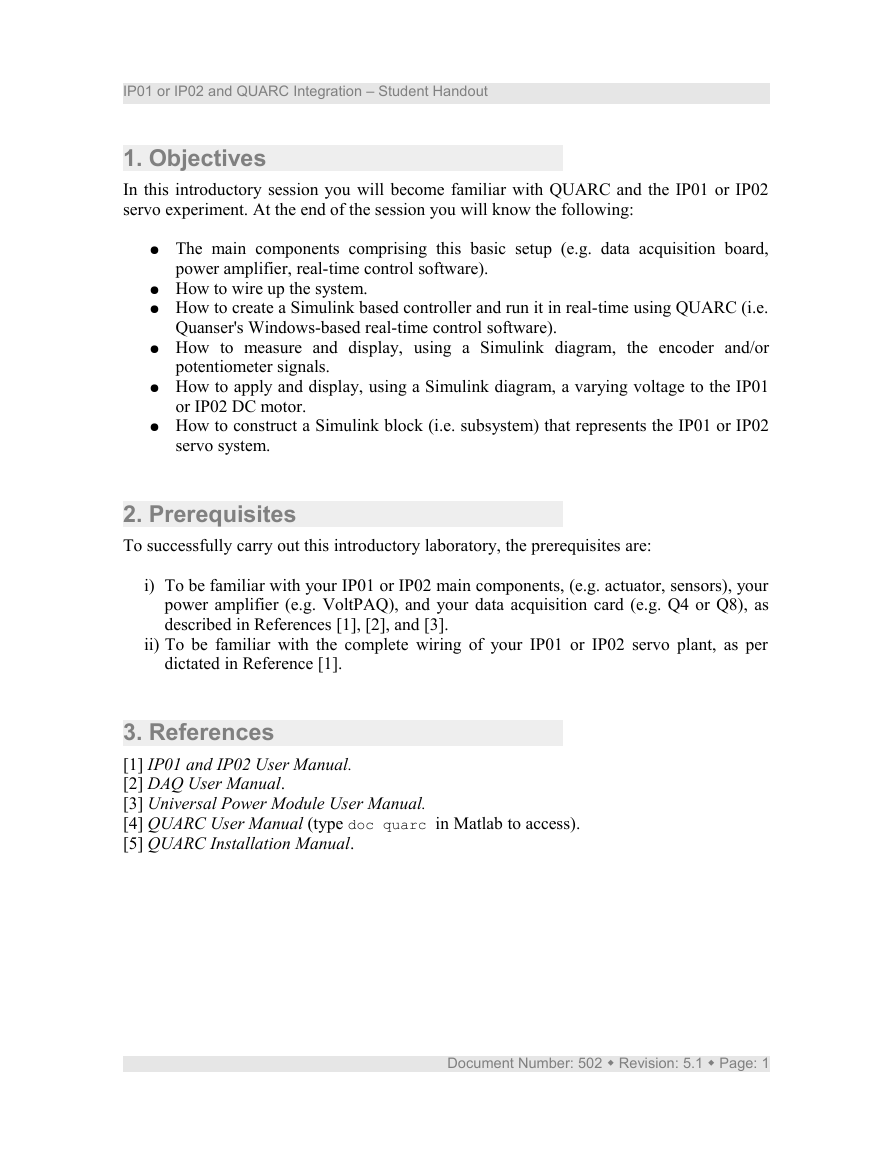
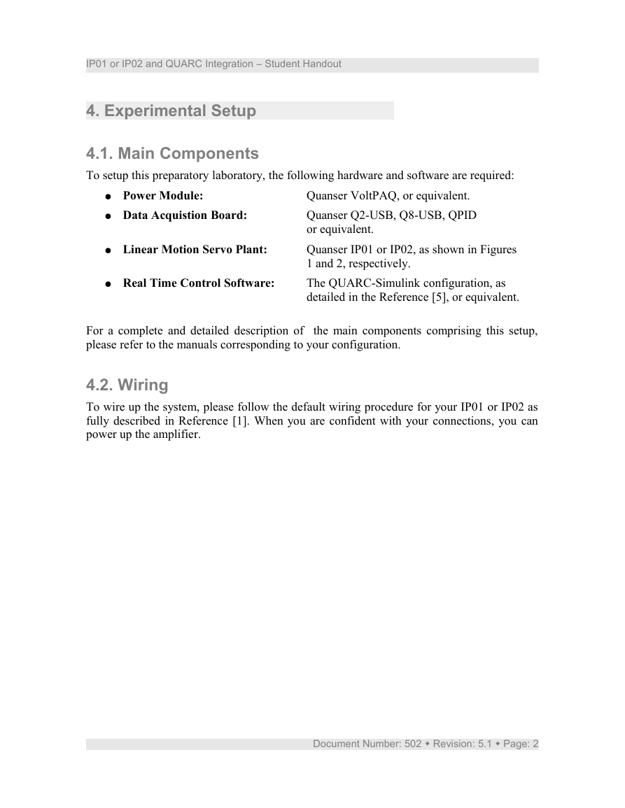
Quanser IP01 or IP02, as shown in Figures
1 and 2, respectively.
The QUARC-Simulink configuration, as
detailed in the Reference [5], or equivalent.
For a complete and detailed description of the main components comprising this setup,
please refer to the manuals corresponding to your configuration.
4.2. Wiring
To wire up the system, please follow the default wiring procedure for your IP01 or IP02 as
fully described in Reference [1]. When you are confident with your connections, you can
power up the amplifier.
Document Number: 502 Revision: 5.1 Page: 2
�
IP01 or IP02 and QUARC Integration – Student Handout
Figure 1 IP01 System
Figure 2 IP02 System
Document Number: 502 Revision: 5.1 Page: 3
�
IP01 or IP02 and QUARC Integration – Student Handout
5. IP01 or IP02 and QUARC Integration
5.1. Applying a Voltage to the DC Motor
The IP01 or IP02 DC motor is driven by an amplifier (e.g. VoltPAQ) suitable to deliver the
desired power to it. In order to drive a voltage to the motor, you need to output the desired
voltage to the desired D/A (i.e. Digital-to-Analog) channel of your data acquisition card
(e.g., Q8, Q4), that is to say the D/A channel connected to the power amplifier. From the
wiring you performed, following the instructions described in [1], it is known that D/A
channel #0 on the data acquisition card drives the amplifier, which in turn drives the IP01
or IP02 DC motor.
5.1.1. Creating the Model
5.1.1.1. Objective
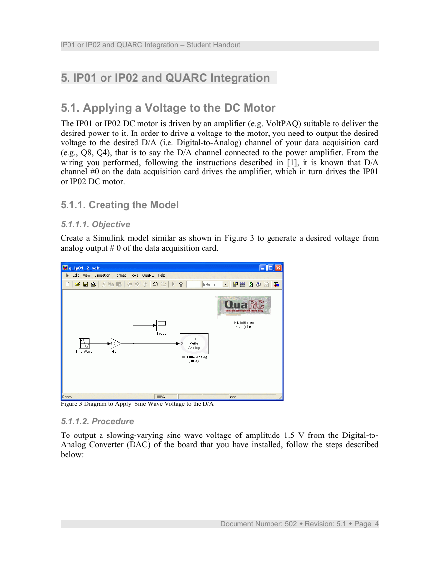
Create a Simulink model similar as shown in Figure 3 to generate a desired voltage from
analog output # 0 of the data acquisition card.
Figure 3 Diagram to Apply Sine Wave Voltage to the D/A
5.1.1.2. Procedure
To output a slowing-varying sine wave voltage of amplitude 1.5 V from the Digital-to-
Analog Converter (DAC) of the board that you have installed, follow the steps described
below:
Document Number: 502 Revision: 5.1 Page: 4
�
IP01 or IP02 and QUARC Integration – Student Handout
1. Load the Matlab software.
2. Create a new Simulink Diagram by clicking on File | New | Model item from the
menu bar.
3. Open the Simulink Library Browser window by clicking on the View | Library
Browser item in the Simulink menu bar or clicking on the Simulink icon.
4. As illustrated in Figure 4, expand the QUARC Targets item and go to the Data
Acquisition \ Generic \ Configuration folder.
5. Click-and-drag the HIL Initialize block from the library window into the blank
Simulink model. This is used to configure your data-acquisition device, e.g. the
Quanser Q4 or Q8 hardware-in-the-loop board.
In the Library Browser, go to the Generic \ Immediate I/O category. This contains
various blocks used to interact with actuators and sensors.
6.
Figure 4: QuaRC Configuration folder in the Simulink Library Browser
window.
7. Click-and-drag the HIL Write Analog block from the library into the Simulink
diagram. This block is used to output a voltage from a digital-to-analog channel, i.e.
Document Number: 502 Revision: 5.1 Page: 5
�
IP01 or IP02 and QUARC Integration – Student Handout
D/A, on the data-acquisition device.
Add the Sine Wave block, found in the Simulink \ Source folder, and the Gain block,
from the Simulink \ Math Operations category, into the Simulink model. Connect
the blocks as shown in Figure 3.
8. Keep the default parameters for the Simulink sine wave block, that is to say, an
amplitude of 1, a frequency of 1 rad/s, and zero bias and phase. Therefore, the sine
wave amplitude, as fed to the analog output block, is set by the subsequent gain
block to 1.5 V.
9. Double-click on the HIL Initialize block.
10. In the Board type field, select the the board that is installed in your PC and which
will be used to communicate with the IP01_2 system, e.g. q4 or q8.
Please have your lab assistant confirm the type of data acquisition card (e.g.,
Q8, Q4) that is installed in the computer and that you are using. Ensure the
HIL Initialize block is configured for the data-acquisition device installed in
your PC and that you will be using.
11. If more than one board of same type is installed, ensure the Board number field is
set correctly, e.g. if two boards are used then choose either 0 or 1.
12. The default settings for the board should fine for this experiment. For more
information on this block, click on its Help button. Otherwise click on the OK
button and proceed.
13. Double-click on the HIL Write Analog block.
14. Set Board name to HIL-1. By default, Channels is set to 0 and the Sample time field
is set to -1. Recall that, as instructed in Reference 1, the DC motor is connected to
Analog Output Channel #0 on the hardware-in-the-loop board. Therefore Channels
should be set to 0. Also, setting the Sample Time to -1 implies that the sampling
interval is inherited from the previous block. This setting is fine as well.
15. Click on the OK button to save and close the HIL Write Analog block properties.
CAUTION:
If a "To Load" cable (as described in Reference [1]) with a gain other than one is being
used (to connect the amplifier to the DC motor), a Gain block should be inserted before the
Analog Output block with a gain of "1 / cable gain" in order to obtain overall closed-loop
unity gain.
5.1.2. Compiling the Model
5.1.2.1. Objective
To compile the designed model into real-time code that will be executable by QUARC.
Document Number: 502 Revision: 5.1 Page: 6
�





 2023年江西萍乡中考道德与法治真题及答案.doc
 2012年重庆南川中考生物真题及答案.doc
 2013年江西师范大学地理学综合及文艺理论基础考研真题.doc
 2020年四川甘孜小升初语文真题及答案I卷.doc
 2020年注册岩土工程师专业基础考试真题及答案.doc
 2023-2024学年福建省厦门市九年级上学期数学月考试题及答案.doc
 2021-2022学年辽宁省沈阳市大东区九年级上学期语文期末试题及答案.doc
 2022-2023学年北京东城区初三第一学期物理期末试卷及答案.doc
 2018上半年江西教师资格初中地理学科知识与教学能力真题及答案.doc
 2012年河北国家公务员申论考试真题及答案-省级.doc
 2020-2021学年江苏省扬州市江都区邵樊片九年级上学期数学第一次质量检测试题及答案.doc
 2022下半年黑龙江教师资格证中学综合素质真题及答案.doc