Version 3.0
Technical Brief
Release 1.0
May 15, 2008
�
Document Change History
Ver
1
Date
Resp
May 15, 2008
GG, LB, AT
Reason for change
Initial revision.
ii
�
Introduction
The Mobile PCI Express Module (MXM) is a standard graphics interface for PCI Express systems.
This technical brief document summarizes the MXM version 3.0 specifications as well as highlighting
the benefits of MXM version 3.0.
Target Markets
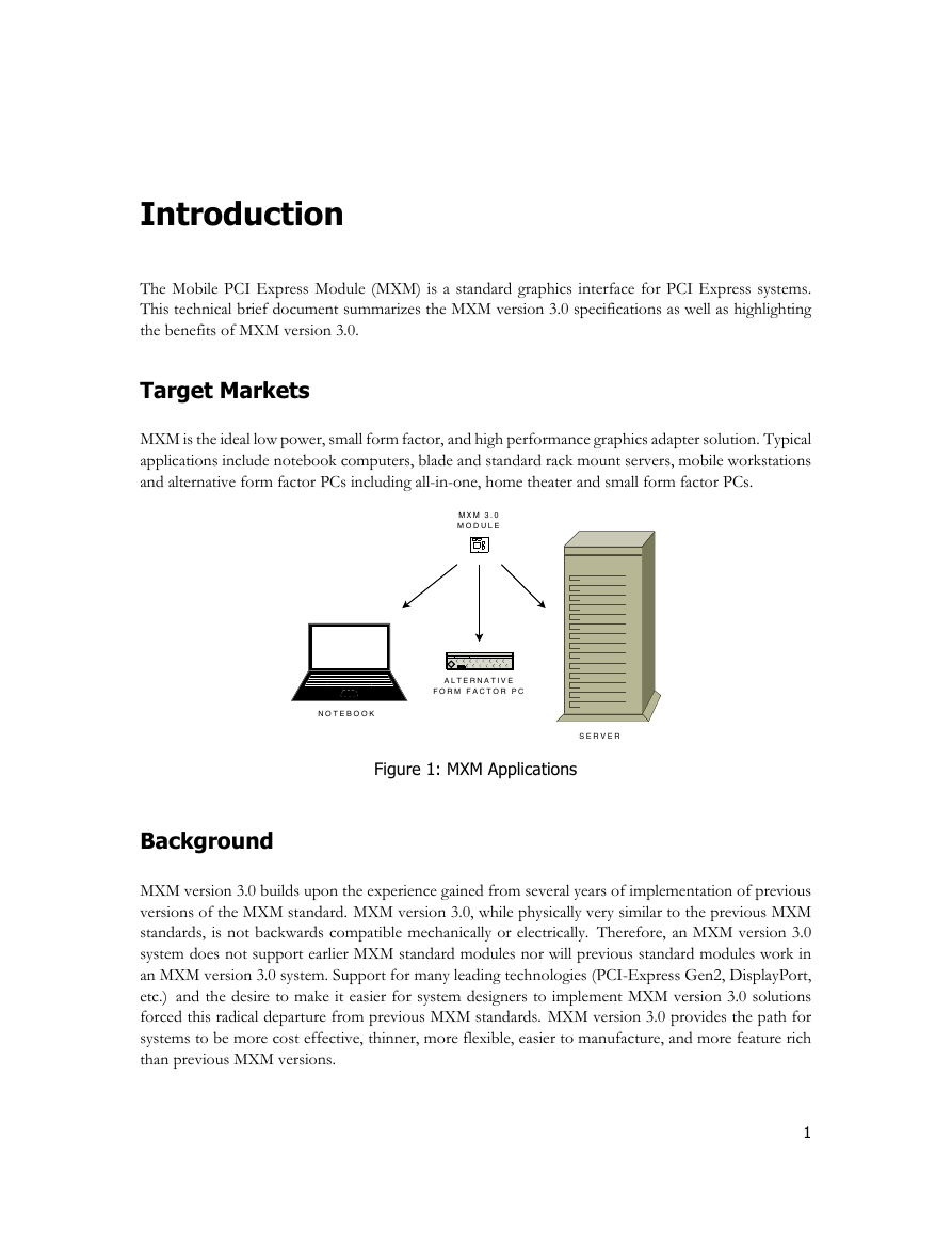
MXM is the ideal low power, small form factor, and high performance graphics adapter solution. Typical
applications include notebook computers, blade and standard rack mount servers, mobile workstations
and alternative form factor PCs including all-in-one, home theater and small form factor PCs.
Figure 1: MXM Applications
Background
MXM version 3.0 builds upon the experience gained from several years of implementation of previous
versions of the MXM standard. MXM version 3.0, while physically very similar to the previous MXM
standards, is not backwards compatible mechanically or electrically. Therefore, an MXM version 3.0
system does not support earlier MXM standard modules nor will previous standard modules work in
an MXM version 3.0 system. Support for many leading technologies (PCI-Express Gen2, DisplayPort,
etc.) and the desire to make it easier for system designers to implement MXM version 3.0 solutions
forced this radical departure from previous MXM standards. MXM version 3.0 provides the path for
systems to be more cost effective, thinner, more flexible, easier to manufacture, and more feature rich
than previous MXM versions.
1
MXM 3.0MODULENOTEBOOKALTERNATIVEFORM FACTOR PCSERVER�
MXM Version 3.0 Technical Brief
Module Compatibility
The goal of the MXM version 3.0 specification is to achieve a level of module interchangeability similar
to a desktop system. A compliant module will properly operate in any compliant system without
any hardware or firmware modification to either the module or the system. This goal is achieved by
defining both software and hardware interfaces. The MXM version 3.0 specification comprises of
two detailed specification documents, a hardware specification covering the electrical, mechanical and
thermal aspects and a software specification.
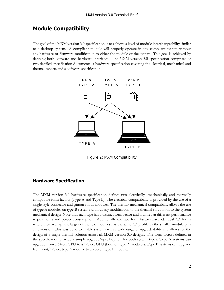
Figure 2: MXM Compatibility
Hardware Specification
The MXM version 3.0 hardware specification defines two electrically, mechanically and thermally
compatible form factors (Type A and Type B). The electrical compatibility is provided by the use of a
single style connector and pinout for all modules. The thermo-mechanical compatibility allows the use
of type A modules on type B systems without any modification to the thermal solution or to the system
mechanical design. Note that each type has a distinct form factor and is aimed at different performance
requirements and power consumption. Additionally the two form factors have identical 3D forms
where they overlap; the larger of the two modules has the same 3D profile as the smaller module plus
an extension. This was done to enable systems with a wide range of upgradeability and allows for the
design of a single thermal solution across all MXM version 3.0 designs. The form factors defined in
the specification provide a simple upgrade/upsell option for both system types. Type A systems can
upgrade from a 64-bit GPU to a 128-bit GPU (both on type A modules). Type B systems can upgrade
from a 64/128-bit type A module to a 256-bit type B module.
2
TYPE ATYPE B64-bTYPE A128-bTYPE A256-bTYPE B�
MXM Version 3.0 Technical Brief
Software Specification
The MXM version 3.0 software specification decouples the graphics module from the system and
defines the functional interface between the two. The MXM software infrastructure resides in the
system BIOS of the system and includes the characteristics of the system mainly with respect to thermal
(graphics power supported by the system) and display configuration (LVDS, DVI, HDMI, DisplayPort,
etc.). To complement the software specification and help software designer implementations many
MXM version 3.0 software tools are available including an MXM Structure edition tool (MXMedit),
system validation tools and sample code.
Major Features
MXM version 3.0 supports the following features:
K up to 16 lanes PCIe Gen2
K 64-b, 128-b and 256-b memory interface using up to 8 DDR2, DDR3, GDDR3, GDDR5
memory devices
K up to 4 Dual mode Display Ports (with support for DVI/HDMI)
K one 24-bit dual link LVDS
K one legacy analog display (multiplexed VGA/TV)
3
�
MXM Version 3.0 Technical Brief
Benefits
MXM version 3.0 reduces significantly the design complexity to integrate graphics modules in a system,
accelerating time to market while reducing incremental qualification effort. End users will see a wider
selection of graphics options, and faster time-to-market for new GPU hardware.
Reduced Cost
The MXM version 3.0 specification reduces the number of system power rails as well as the mandatory
system power required. The use of a single connector allows for better economy of scale. Optimized
form factor and height zones provide very cost effective power supply solutions.
Thermo-mechanical Compatibility
Full thermo-mechanical compatibility between module types eliminate the need to trade off between
which MXM type to use. MXM version 3.0 allows a general increase in the power density thanks to a
well defined thermal environment. There is no need for backside cooling and the new connector design
properly supports PCI-Express Gen2 and DisplayPort signal integrity requirements.
System Optimized Z-height
Recognizing the need for lower z-height systems, especially for notebooks, MXM version 3.0 focused
on the critical system height stack and reduced the z-height requirement of MXM type A by more than
1 mm compared to previous MXM implementations. Support for an inline connector is also being
investigated to further improve the graphic subsystem z-height contribution to the overall z-height of
the system.
Future Proof
MXM version 3.0 is designed with the future in mind. It is planned to have at least a 3 year life span
with its support for complex display configurations (including the newest DisplayPort standard) that
eliminates multiplexer on the system board, several reserved pins, and alignment with the appearance
of PCI-Express Gen2 in the mass market.
Other Benefits
Improved boot time, advanced thermal control capability, simplification of graphics module assembly
within systems, and the support for OEM customization pins will also benefit members of the MXM
version 3.0 ecosystem.
4
�
Implementation Details
This section provides a brief overview of the MXM version 3.0 implementation. Refer to the MXM
Hardware Specification for details.
Form Factors
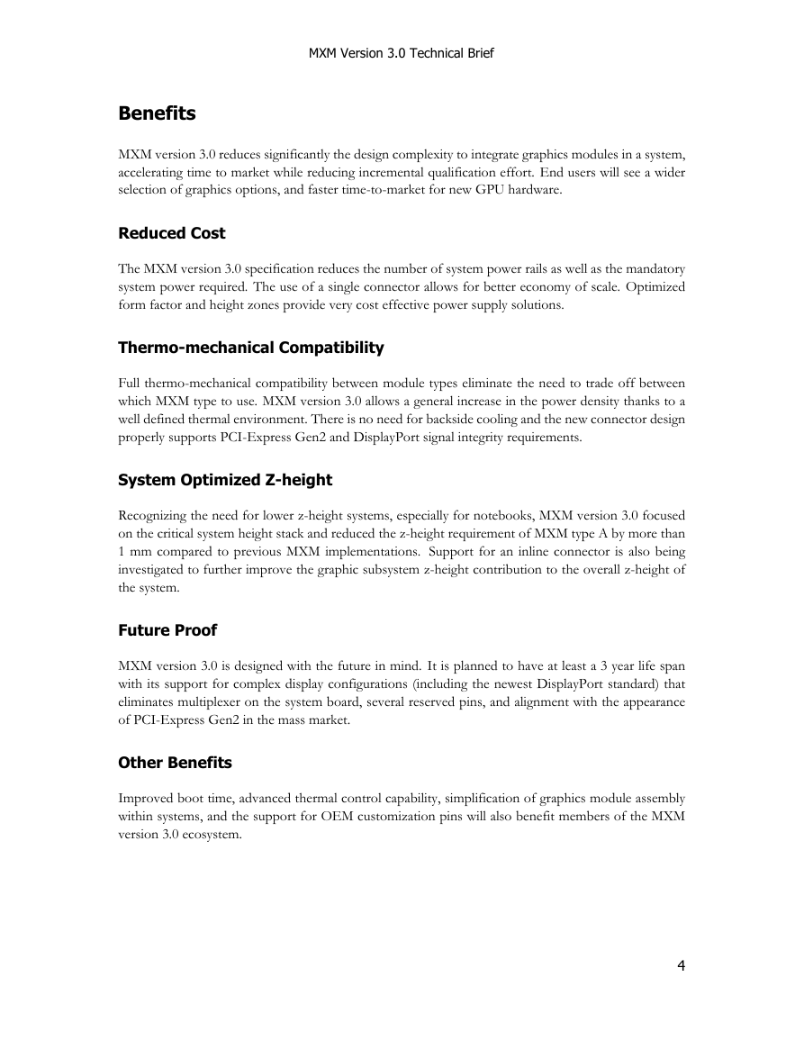
MXM version 3.0 specification defines two electrically, mechanically and thermally compatible form
factors. These two form factors are shown in Figure 3.
Type A Module
Type A targets mid-range and performance systems
K Board size: 82x70mm
K GPU: 64/128-bit (optimized for 29x29mm)
K TGP: Cost optimized for 35W
Type B Module
Type B targets high-performance and enthusiast systems
K Board size: 82x105mm
K GPU: 256-bit (optimized for 35x35mm)
K TGP: Cost optimized for 75W
Input Voltages
MXM version 3.0 requires the following voltages:
K 7-20V (battery) up to 10A (depending on system capability and charge status)
K 5V 2.5A
K 3.3V 1A
5
�
MXM Version 3.0 Technical Brief
Figure 3: MXM Form Factors
Edge-Fingers
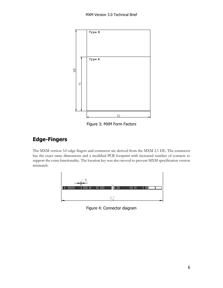
The MXM version 3.0 edge-fingers and connector are derived from the MXM 2.1 HE. The connector
has the exact same dimensions and a modified PCB footprint with increased number of contacts to
support the extra functionality. The location key was also moved to prevent MXM specification version
mismatch.
Figure 4: Connector diagram
6
�




 2023年江西萍乡中考道德与法治真题及答案.doc
 2012年重庆南川中考生物真题及答案.doc
 2013年江西师范大学地理学综合及文艺理论基础考研真题.doc
 2020年四川甘孜小升初语文真题及答案I卷.doc
 2020年注册岩土工程师专业基础考试真题及答案.doc
 2023-2024学年福建省厦门市九年级上学期数学月考试题及答案.doc
 2021-2022学年辽宁省沈阳市大东区九年级上学期语文期末试题及答案.doc
 2022-2023学年北京东城区初三第一学期物理期末试卷及答案.doc
 2018上半年江西教师资格初中地理学科知识与教学能力真题及答案.doc
 2012年河北国家公务员申论考试真题及答案-省级.doc
 2020-2021学年江苏省扬州市江都区邵樊片九年级上学期数学第一次质量检测试题及答案.doc
 2022下半年黑龙江教师资格证中学综合素质真题及答案.doc