logo资料库

ACER笔记本电脑-Aspire 3935说明书.pdf

第1页 / 共39页
第2页 / 共39页
第3页 / 共39页
第4页 / 共39页
第5页 / 共39页
第6页 / 共39页
第7页 / 共39页
第8页 / 共39页
资料共39页,剩余部分请下载后查看
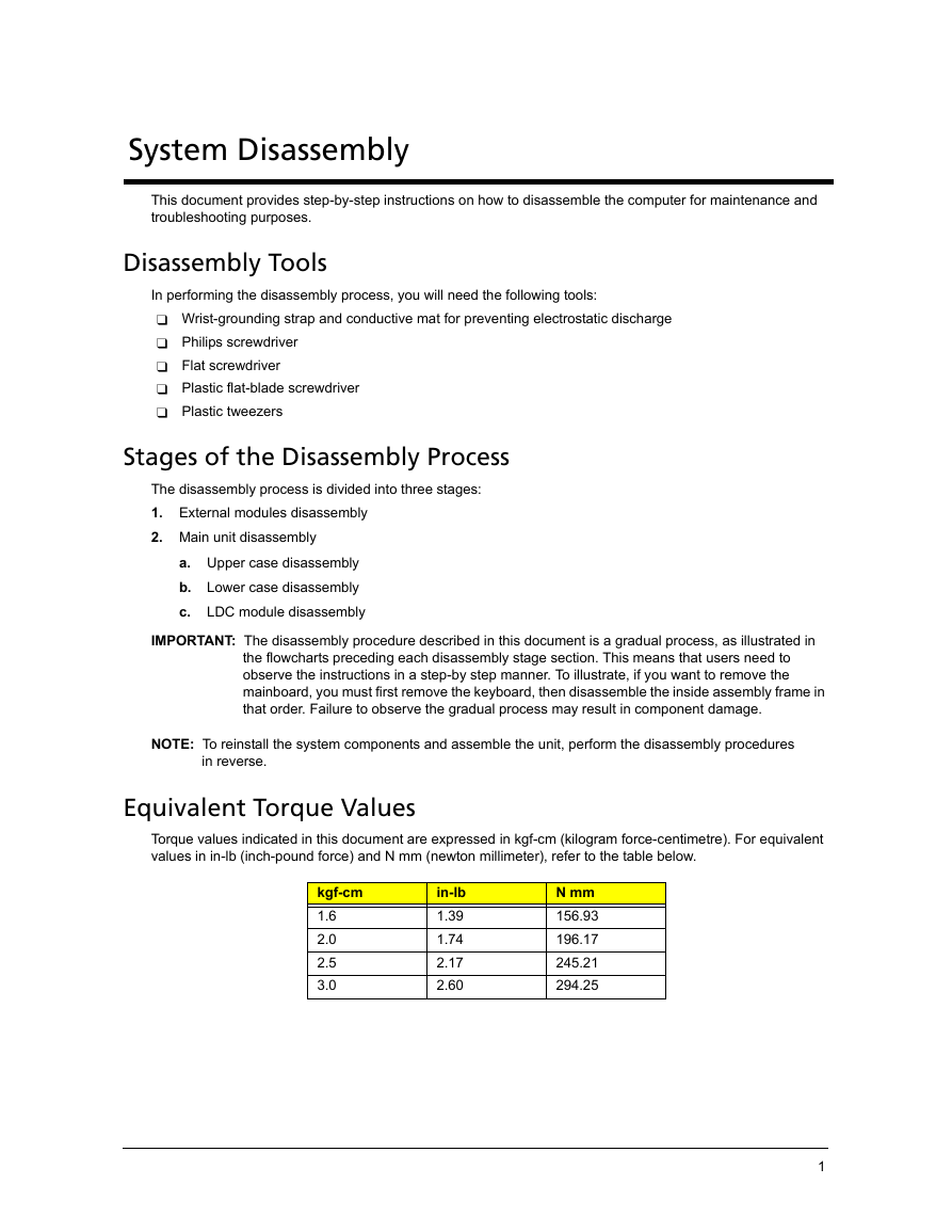
Acer Aspire 3935 Notebook Computer Disassembly Instructions
System Disassembly
Disassembly Tools
Stages of the Disassembly Process
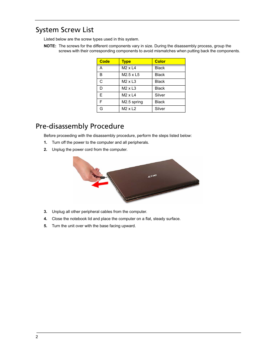
Equivalent Torque Values
System Screw List
Pre-disassembly Procedure
External Modules Disassembly
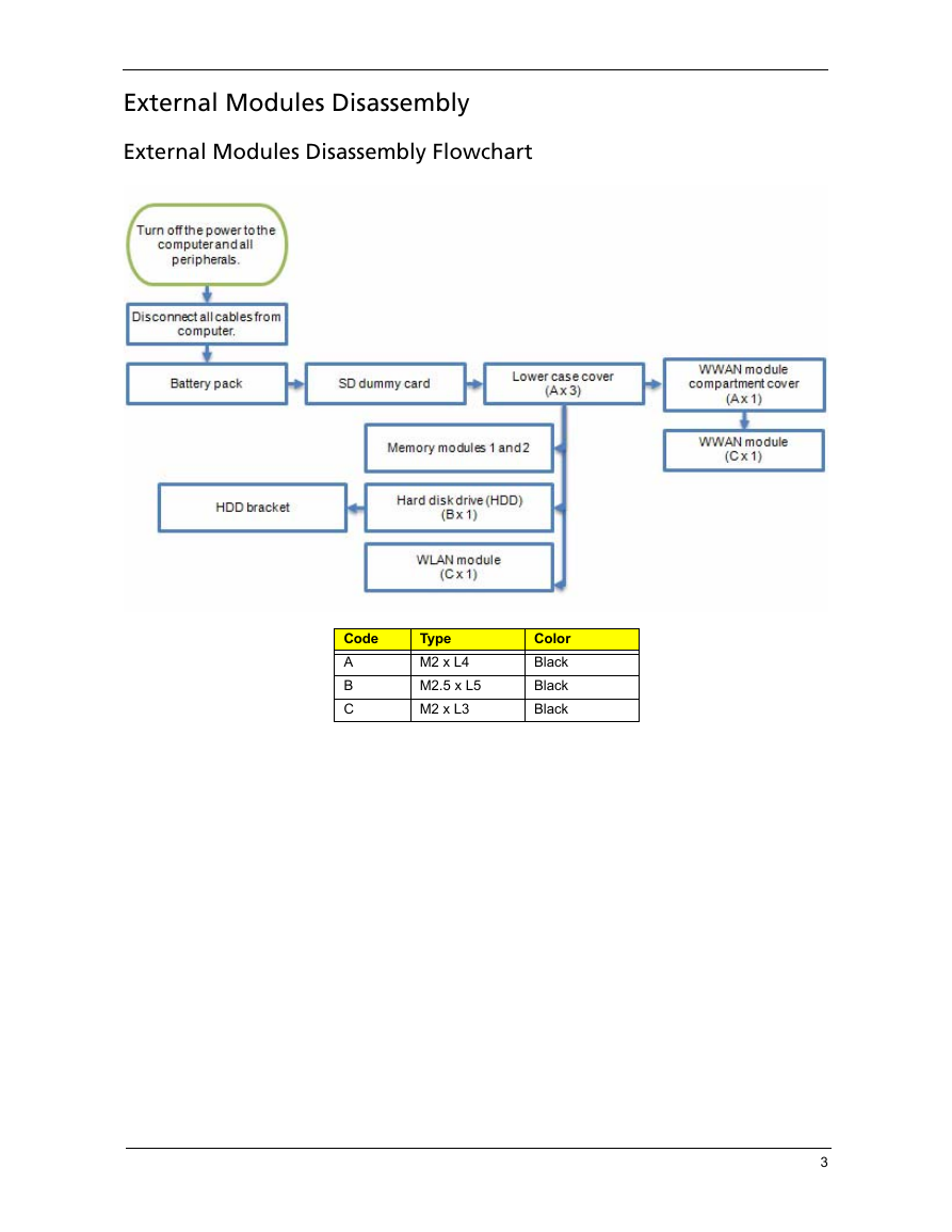
External Modules Disassembly Flowchart
Removing the Battery Pack
Removing the SD Dummy Card
Removing the Lower Case Cover
Removing the Memory Modules
Removing the Hard Disk Drive
Removing the WLAN Module
Removing the WWAN (3G) Module
Main Unit Disassembly
Main Unit Disassembly Flowchart
Removing the Middle Cover
Removing the Keyboard
Removing the LCD Module
Removing the Upper Case
Removing the Speakers
Removing the Thermal Bracket
Removing the Fingerprint Reader Board
Removing the Microphone
Removing the Touchpad Board
Removing the Cover Switch Cable
Removing the Optical Disc Drive
Removing the Mainboard
Removing the Heat Sink Fan (HSF) Assembly
Removing the Processor
Removing the I/O Board
Removing the DC-in Cable
LCD Module Disassembly
LCD Module Disassembly Flowchart
Removing the LCD Bezel
Removing the LCD Panel
Removing the LCD Panel Brackets
Removing the CCD Board
Acer Aspire 3935 Notebook Computer Disassembly Instructions
System Disassembly This document provides step-by-step instructions on how to disassemble the computer for maintenance and troubleshooting purposes. Disassembly Tools In performing the disassembly process, you will need the following tools:  Wrist-grounding strap and conductive mat for preventing electrostatic discharge  Philips screwdriver  Flat screwdriver  Plastic flat-blade screwdriver  Plastic tweezers Stages of the Disassembly Process The disassembly process is divided into three stages: 1. External modules disassembly 2. Main unit disassembly a. Upper case disassembly b. Lower case disassembly c. LDC module disassembly IMPORTANT: The disassembly procedure described in this document is a gradual process, as illustrated in the flowcharts preceding each disassembly stage section. This means that users need to observe the instructions in a step-by step manner. To illustrate, if you want to remove the mainboard, you must first remove the keyboard, then disassemble the inside assembly frame in that order. Failure to observe the gradual process may result in component damage. NOTE: To reinstall the system components and assemble the unit, perform the disassembly procedures  in reverse. Equivalent Torque Values Torque values indicated in this document are expressed in kgf-cm (kilogram force-centimetre). For equivalent values in in-lb (inch-pound force) and N mm (newton millimeter), refer to the table below. kgf-cm 1.6 2.0 2.5 3.0 in-lb 1.39 1.74 2.17 2.60 N mm 156.93 196.17 245.21 294.25 1
System Screw List Listed below are the screw types used in this system. NOTE: The screws for the different components vary in size. During the disassembly process, group the screws with their corresponding components to avoid mismatches when putting back the components. Code A B C D E F G Type M2 x L4 M2.5 x L5 M2 x L3 M2 x L3 M2 x L4 M2.5 spring M2 x L2 Color Black Black Black Black Silver Black Silver Pre-disassembly Procedure Before proceeding with the disassembly procedure, perform the steps listed below: 1. Turn off the power to the computer and all peripherals. 2. Unplug the power cord from the computer. 3. Unplug all other peripheral cables from the computer. 4. Close the notebook lid and place the computer on a flat, steady surface. 5. Turn the unit over with the base facing upward. 2
External Modules Disassembly External Modules Disassembly Flowchart Code A B C Type M2 x L4 M2.5 x L5 M2 x L3 Color Black Black Black 3
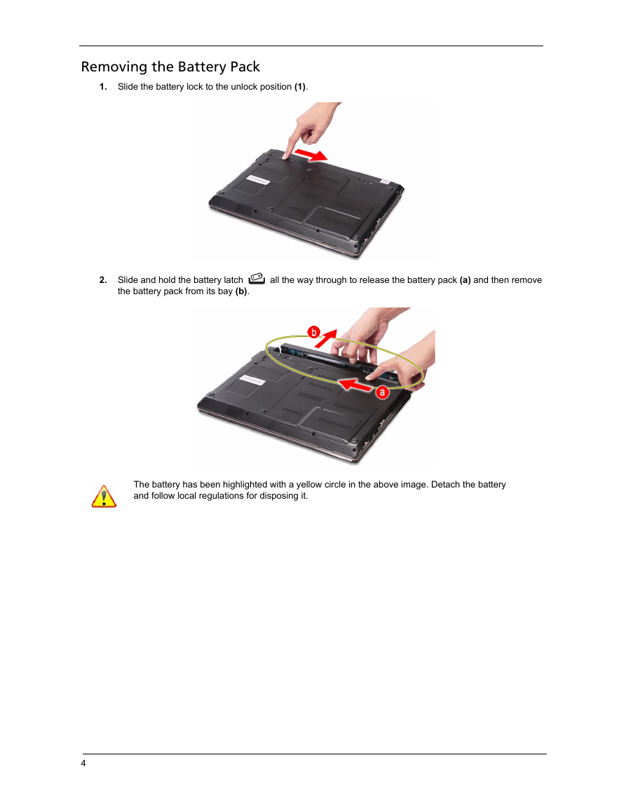
Removing the Battery Pack 1. Slide the battery lock to the unlock position (1). 2. Slide and hold the battery latch the battery pack from its bay (b). all the way through to release the battery pack (a) and then remove The battery has been highlighted with a yellow circle in the above image. Detach the battery and follow local regulations for disposing it. 4
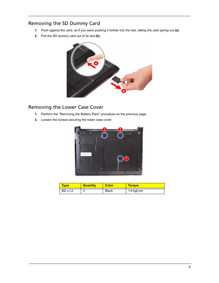
Removing the SD Dummy Card 1. Push against the card, as if you were pushing it further into the slot, letting the card spring out (a). 2. Pull the SD dummy card out of its slot (b). Removing the Lower Case Cover 1. Perform the “Removing the Battery Pack” procedure on the previous page. 2. Loosen the screws securing the lower case cover. Type M2 x L4 Quantity 3 Color Black Torque 1.6 kgf-cm 5
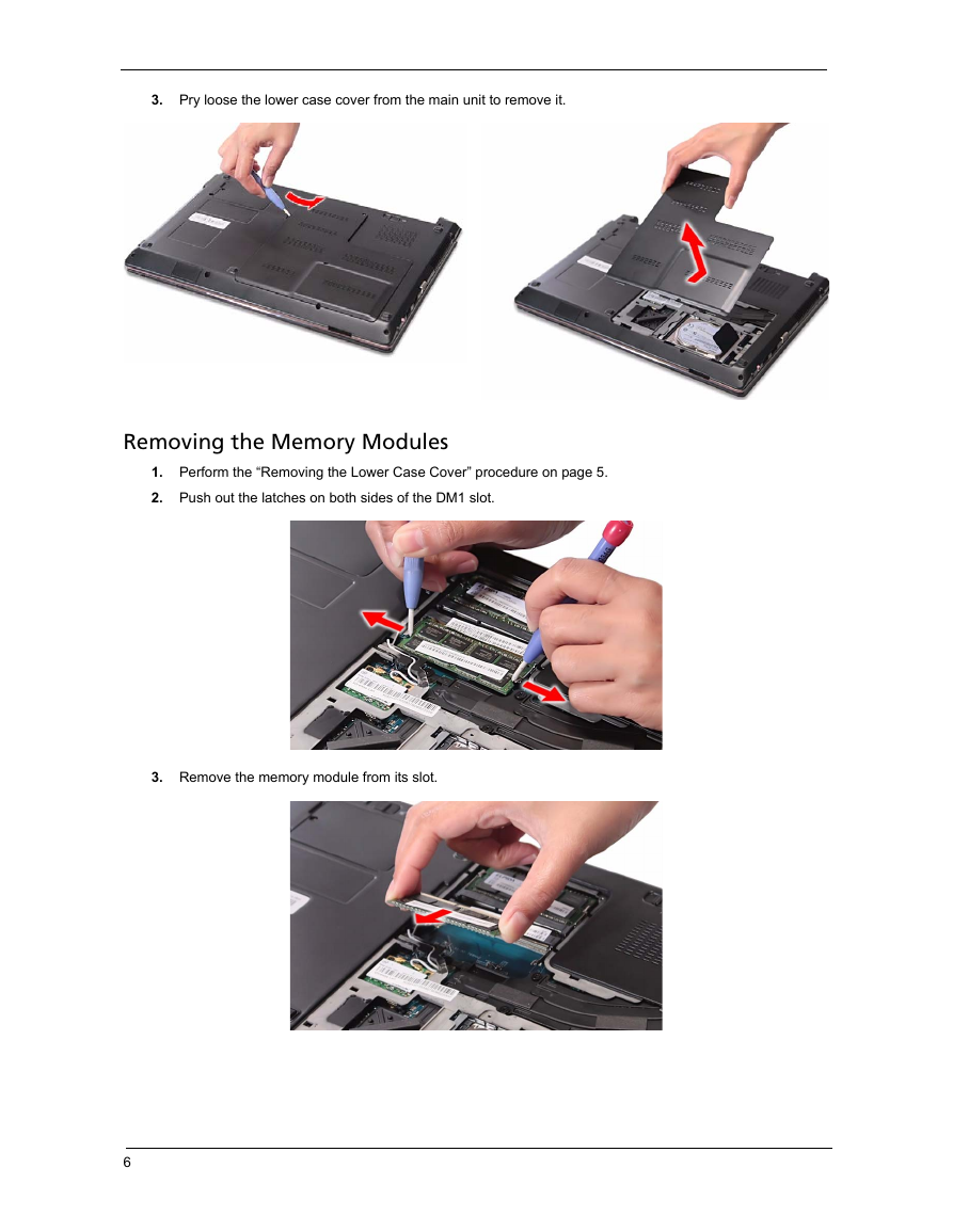
3. Pry loose the lower case cover from the main unit to remove it. Removing the Memory Modules 1. Perform the “Removing the Lower Case Cover” procedure on page 5. 2. Push out the latches on both sides of the DM1 slot. 3. Remove the memory module from its slot. 6
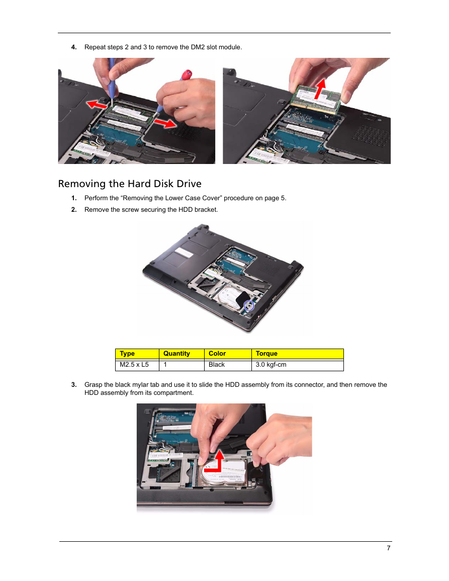
4. Repeat steps 2 and 3 to remove the DM2 slot module. Removing the Hard Disk Drive 1. Perform the “Removing the Lower Case Cover” procedure on page 5. 2. Remove the screw securing the HDD bracket. Type M2.5 x L5 Quantity 1 Color Black Torque 3.0 kgf-cm 3. Grasp the black mylar tab and use it to slide the HDD assembly from its connector, and then remove the HDD assembly from its compartment. 7
分享到:
收藏