Acknowledgements
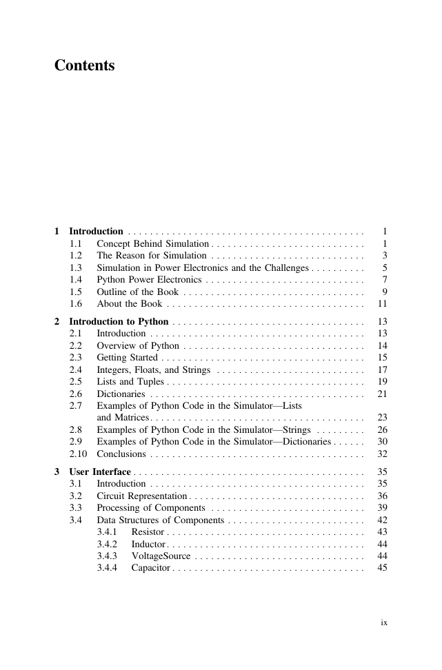
Contents
1 Introduction
1.1 Concept Behind Simulation
1.2 The Reason for Simulation
1.3 Simulation in Power Electronics and the Challenges
1.4 Python Power Electronics
1.5 Outline of the Book
1.6 About the Book
2 Introduction to Python
2.1 Introduction
2.2 Overview of Python
2.3 Getting Started
2.4 Integers, Floats, and Strings
2.5 Lists and Tuples
2.6 Dictionaries
2.7 Examples of Python Code in the Simulator—Lists and Matrices
2.8 Examples of Python Code in the Simulator—Strings
2.9 Examples of Python Code in the Simulator—Dictionaries
2.10 Conclusions
3 User Interface
3.1 Introduction
3.2 Circuit Representation
3.3 Processing of Components
3.4 Data Structures of Components
3.4.1 Resistor
3.4.2 Inductor
3.4.3 VoltageSource
3.4.4 Capacitor
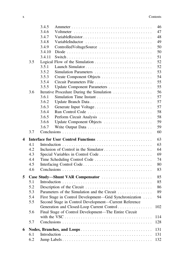
3.4.5 Ammeter
3.4.6 Voltmeter
3.4.7 VariableResistor
3.4.8 VariableInductor
3.4.9 ControlledVoltageSource
3.4.10 Diode
3.4.11 Switch
3.5 Logical Flow of the Simulation
3.5.1 Launch Simulator
3.5.2 Simulation Parameters
3.5.3 Create Component Objects
3.5.4 Circuit Parameters File
3.5.5 Update Component Parameters
3.6 Iterative Procedure During the Simulation
3.6.1 Simulation Time Instant
3.6.2 Update Branch Data
3.6.3 Generate Input Voltage
3.6.4 Run Control Code
3.6.5 Perform Circuit Analysis
3.6.6 Update Component Objects
3.6.7 Write Output Data
3.7 Conclusions
4 Interface for User Control Functions
4.1 Introduction
4.2 Inclusion of Control in the Simulator
4.3 Special Variables in Control Code
4.4 Time Scheduling Control Code
4.5 Interfacing Control Code
4.6 Conclusions
5 Case Study—Shunt VAR Compensator
5.1 Introduction
5.2 Description of the Circuit
5.3 Parameters of the Simulation and the Circuit
5.4 First Stage in Control Development—Grid Synchronization
5.5 Second Stage in Control Development—Current Reference Generation and Closed-Loop Current Control
5.6 Final Stage of Control Development—The Entire Circuit with the VSC
5.7 Conclusions
6 Nodes, Branches, and Loops
6.1 Introduction
6.2 Jump Labels
6.3 Nodes and Branches
6.4 Short Branches and Nodes
6.5 Connectivity Map for Nodal Analysis
6.6 Loops
6.7 Loop Map
6.8 Conclusions
7 Circuit Analysis—Loop Analysis
7.1 Introduction
7.2 Matrices for Loop Analysis
7.3 Solving the Matrix Equation
7.4 Mapping Branch Currents and Loop Currents
7.5 Effects of Time Constants on Loop Analysis
7.6 Effect of Stiff Loops
7.7 Loop Manipulations
7.8 Limitation of Loop Analysis
7.9 Conclusions
8 Circuit Analysis—Nodal Analysis
8.1 Introduction
8.2 Concept of Nodal Analysis
8.3 Limitation of Loop Analysis in Nonlinear Circuits
8.4 Applying Nodal Analysis in Nonlinear Circuits
8.5 Continuing with Loop Analysis
8.6 Event-Driven Circuit Updates
8.7 Process Flow in the Simulator
8.8 Conclusions
9 Conclusions
9.1 Advantages of the Simulator
9.2 Drawbacks of the Simulator and Scope for Future Work
9.3 Future of the Project
Bibliography




 2023年江西萍乡中考道德与法治真题及答案.doc
 2012年重庆南川中考生物真题及答案.doc
 2013年江西师范大学地理学综合及文艺理论基础考研真题.doc
 2020年四川甘孜小升初语文真题及答案I卷.doc
 2020年注册岩土工程师专业基础考试真题及答案.doc
 2023-2024学年福建省厦门市九年级上学期数学月考试题及答案.doc
 2021-2022学年辽宁省沈阳市大东区九年级上学期语文期末试题及答案.doc
 2022-2023学年北京东城区初三第一学期物理期末试卷及答案.doc
 2018上半年江西教师资格初中地理学科知识与教学能力真题及答案.doc
 2012年河北国家公务员申论考试真题及答案-省级.doc
 2020-2021学年江苏省扬州市江都区邵樊片九年级上学期数学第一次质量检测试题及答案.doc
 2022下半年黑龙江教师资格证中学综合素质真题及答案.doc