U S E R ‘ S M A N U A L A
N D P R O G R A M M I N G
G U I D E
VLP-16
Velodyne LiDAR Puck
�
T A B L E O F C O N T E
N T S
V L P - 1 6 U S E R ’ S M A N
U A L
i S A F E T Y N O T I C E S
1 I N T R O D U C T I O N
2 P R I N C I P L E S O F O P E R A T I O N
3 C a l i b r a t e d R e f l e c t i v i t i e s
4 R e t u r n M o d e s
7 S E T U P
7 C a s e C o n t e n t s
7 M o u n t i n g
8 C o n n e c t i o n s
8 P o w e r
8 E t h e r n e t
9 G P S
1 0 U S A G E
1 0 U s i n g t h e S e n s o r
1 2 S E N S O R D A T A
1 2 D a t a P a c k e t F o r m a t
1 6 T i m e S t a m p
1 6 T i m e S t a m p i n g A c c u r a c y
16 6 F a c t o r y B y t e s
17 7 T h e P o s i t i o n P a c k e t
19 9 T R O U B L E S H O O T I N G
1 9 S e r v i c e a n d M a i n t e n a n c e
20 0 S P E C I F I C A T
I O N S 2 1 A P P E N D I
X A
P a c k e t S t r u c t u r e & T i m i n g
2 9 A P P E N D I X B
I n t e r f a c e B o x
34 4 A P P E N D I X C
W e b s e r v e r G U I
35 5 A P P E N D I X D
F i r m w a r e U p d a t e P r o c e d u r e
4 3 A P P E N D I X E
V e l o V i e w
4 4 A P P E N D I X F
M e c h a n i c a l D r a w i n g
�
S A F E T Y N O T I C
E S
V L P - 1 6 U S E R ’ S M A N
U A L
body. Refer servicing to qualified service personnel.
is intended to alert
the user
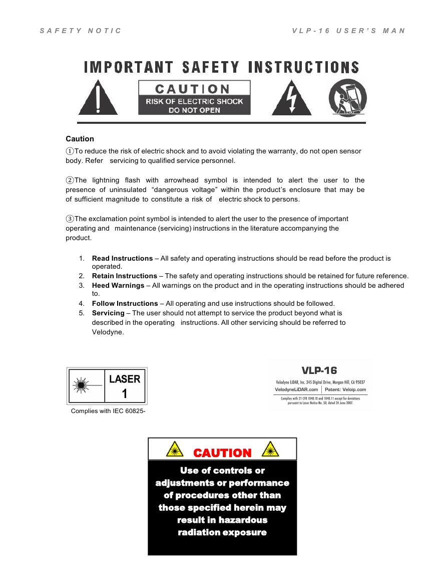
Caution①To reduce the risk of electric shock and to avoid violating the warranty, do not open sensor
②The lightning flash with arrowhead symbol
③The exclamation point symbol is intended to alert the user to the presence of important
to the
presence of uninsulated “dangerous voltage” within the product’s enclosure that may be
of sufficient magnitude to constitute a risk of electric shock to persons.
operating and maintenance (servicing) instructions in the literature accompanying the
product.
1. Read Instructions – All safety and operating instructions should be read before the product is
operated.
2. Retain Instructions – The safety and operating instructions should be retained for future reference.
3. Heed Warnings – All warnings on the product and in the operating instructions should be adhered
to.
4. Follow Instructions – All operating and use instructions should be followed.
5. Servicing – The user should not attempt to service the product beyond what is
described in the operating instructions. All other servicing should be referred to
Velodyne.
Complies with IEC 60825-
1
CAUTION
Use of controls or
adjustments or performance
of procedures other than
those specified herein may
result in hazardous
radiation exposure
�
S A F E T Y N O T I C
E S
V L P - 1 6 U S E R ’ S M A N
U A L
i
�
I N T R O D U C T I
O N
V L P - 1 6 U S E R ’ S M A N
U A L
Congratulations on your purchase of a Velodyne VLP-16 Real-Time 3D LiDAR Sensor. This
sensor provides state-of-
the-art 3D imaging in real time.
This manual describes
format and interpretation, and GPS installation notes.
how to set up and operate the
VLP-16.
It covers
installation and
wiring,
output packet
This manual is undergoing constant revision and improvement – check www.velodynelidar.com for updates.
1
�
P R I N C I P L E S O F O P E R A
T I O N
V L P - 1 6 U S E R ’ S M A N
U A L
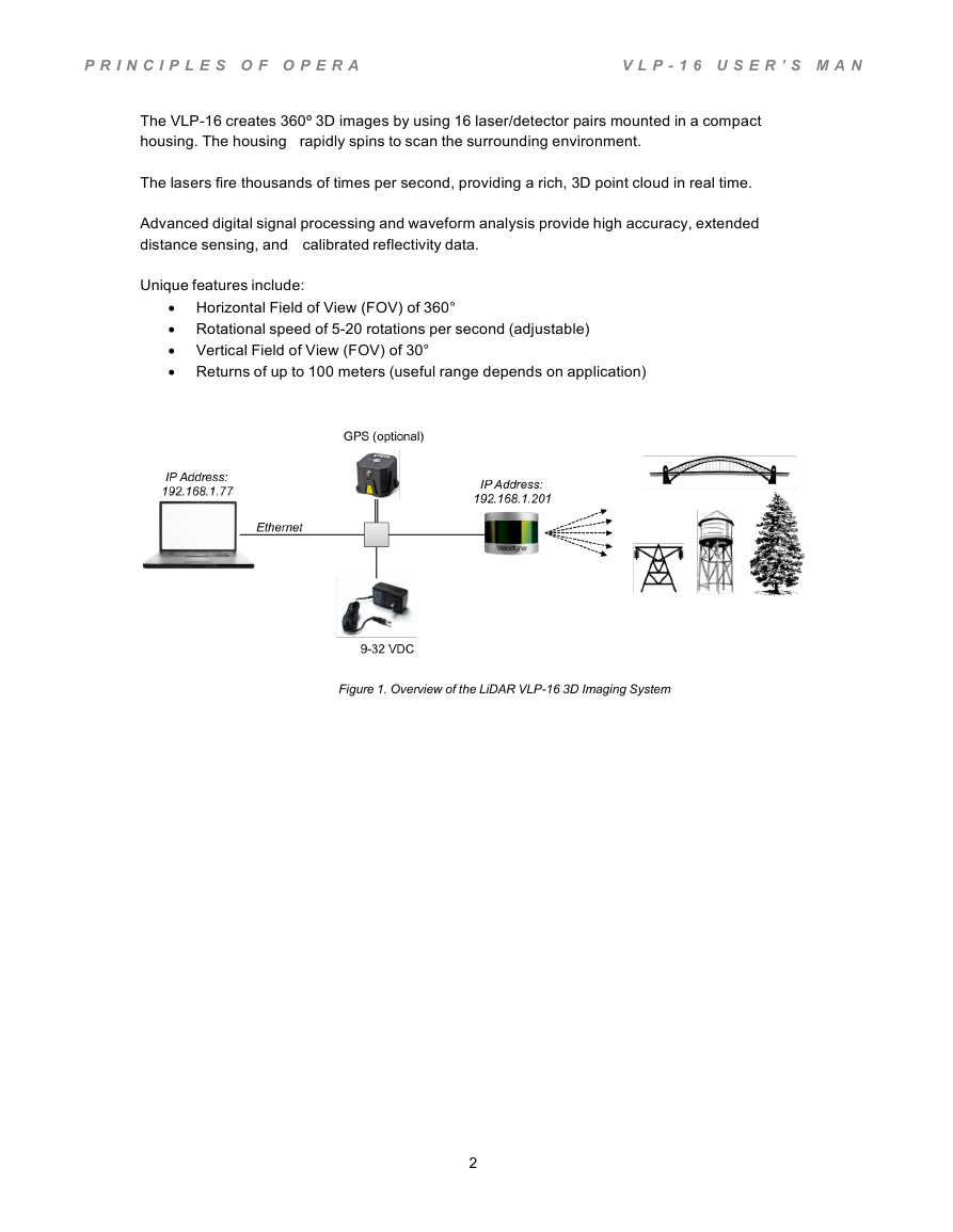
The VLP-16 creates 360º 3D images by using 16 laser/detector pairs mounted in a compact
housing. The housing rapidly spins to scan the surrounding environment.
The lasers fire thousands of times per second, providing a rich, 3D point cloud in real time.
Advanced digital signal processing and waveform analysis provide high accuracy, extended
distance sensing, and calibrated reflectivity data.
Unique features include:
Horizontal Field of View (FOV) of 360°
Rotational speed of 5-20 rotations per second (adjustable)
Returns of up to 100 meters (useful range depends on application)
Vertical Field of View (FOV) of 30°
Figure 1. Overview of the LiDAR VLP-16 3D Imaging System
2
�
P R I N C I P L E S O F O P E R A
T I O N
Calibrated Reflectivities
V L P - 1 6 U S E R ’ S M A N
U A L
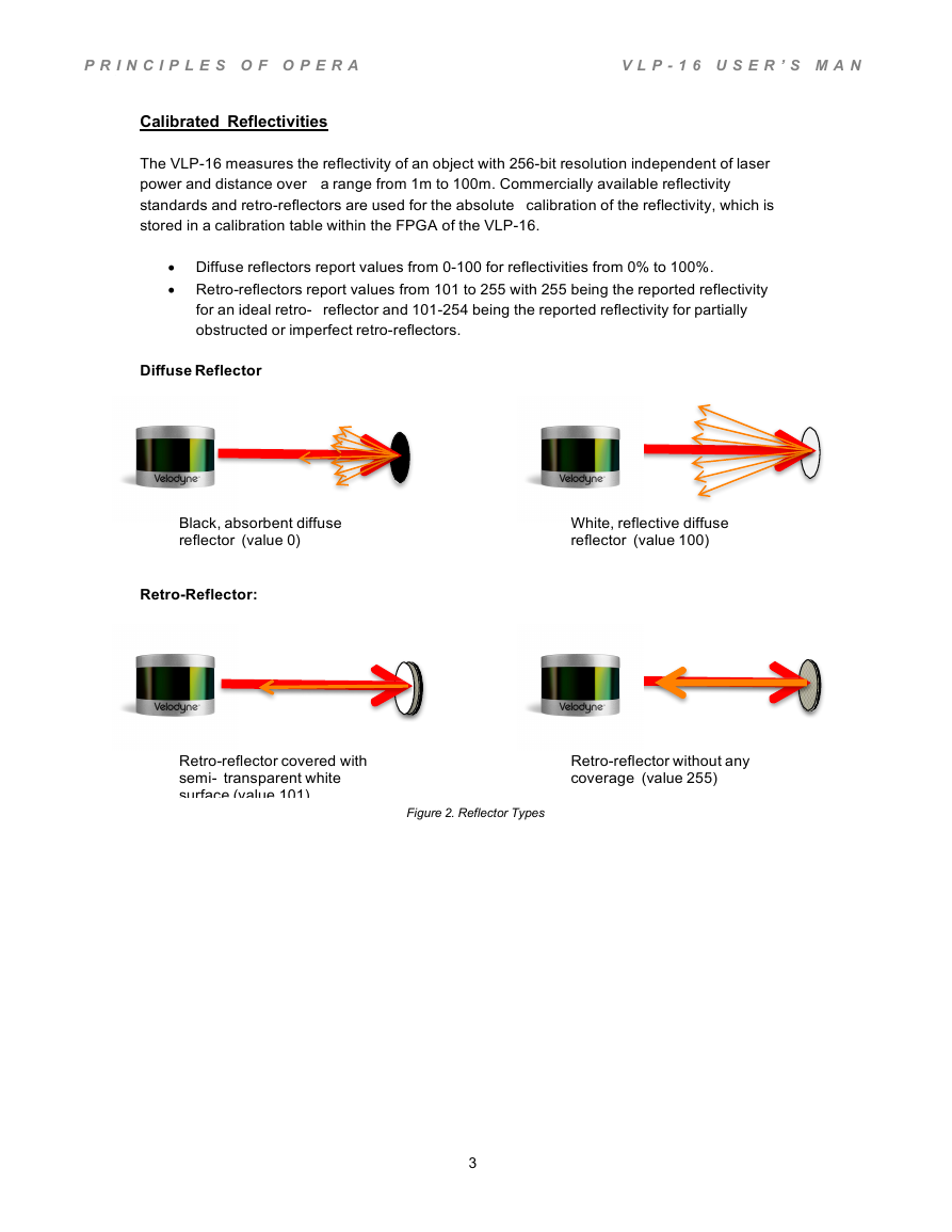
The VLP-16 measures the reflectivity of an object with 256-bit resolution independent of laser
power and distance over a range from 1m to 100m. Commercially available reflectivity
standards and retro-reflectors are used for the absolute calibration of the reflectivity, which is
stored in a calibration table within the FPGA of the VLP-16.
Diffuse reflectors report values from 0-100 for reflectivities from 0% to 100%.
Retro-reflectors report values from 101 to 255 with 255 being the reported reflectivity
for an ideal retro-
obstructed or imperfect retro-reflectors.
reflector and 101-254 being the reported reflectivity for partially
Diffuse Reflector
Black, absorbent diffuse
reflector (value 0)
White, reflective diffuse
reflector (value 100)
Retro-Reflector:
Retro-reflector covered with
semi- transparent white
surface (value 101)
Figure 2. Reflector Types
Retro-reflector without any
coverage (value 255)
3
�
P R I N C I P L E S O F O P E R A
T I O N
Return Modes
V L P - 1 6 U S E R ’ S M A N
U A L
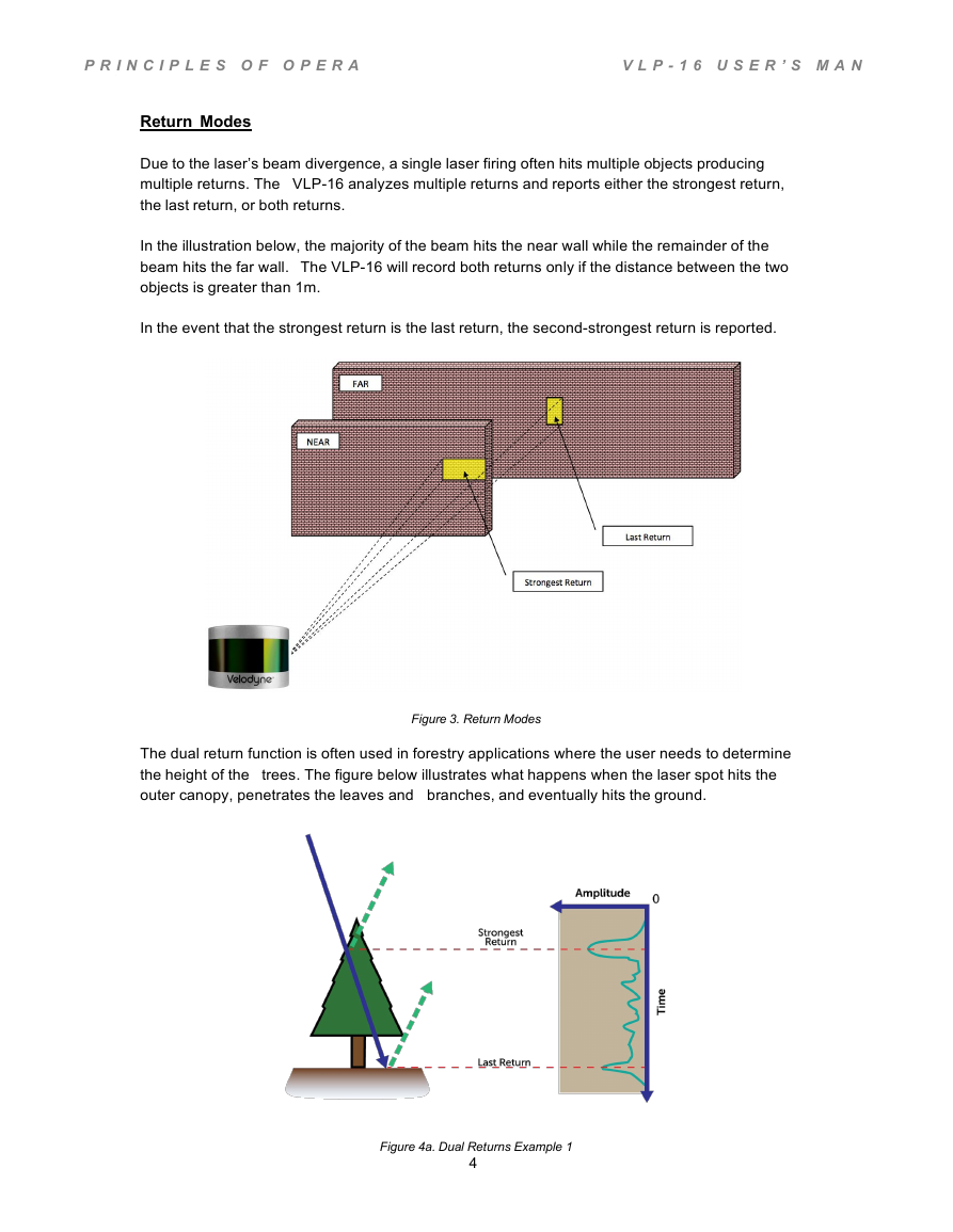
Due to the laser’s beam divergence, a single laser firing often hits multiple objects producing
multiple returns. The VLP-16 analyzes multiple returns and reports either the strongest return,
the last return, or both returns.
In the illustration below, the majority of the beam hits the near wall while the remainder of the
beam hits the far wall. The VLP-16 will record both returns only if the distance between the two
objects is greater than 1m.
In the event that the strongest return is the last return, the second-strongest return is reported.
Figure 3. Return Modes
The dual return function is often used in forestry applications where the user needs to determine
the height of the trees. The figure below illustrates what happens when the laser spot hits the
outer canopy, penetrates the leaves and branches, and eventually hits the ground.
Figure 4a. Dual Returns Example 1
4
�





 2023年江西萍乡中考道德与法治真题及答案.doc
 2012年重庆南川中考生物真题及答案.doc
 2013年江西师范大学地理学综合及文艺理论基础考研真题.doc
 2020年四川甘孜小升初语文真题及答案I卷.doc
 2020年注册岩土工程师专业基础考试真题及答案.doc
 2023-2024学年福建省厦门市九年级上学期数学月考试题及答案.doc
 2021-2022学年辽宁省沈阳市大东区九年级上学期语文期末试题及答案.doc
 2022-2023学年北京东城区初三第一学期物理期末试卷及答案.doc
 2018上半年江西教师资格初中地理学科知识与教学能力真题及答案.doc
 2012年河北国家公务员申论考试真题及答案-省级.doc
 2020-2021学年江苏省扬州市江都区邵樊片九年级上学期数学第一次质量检测试题及答案.doc
 2022下半年黑龙江教师资格证中学综合素质真题及答案.doc