Solutions Manual to Accompany
Homework
For Linear Control
System Engineering
Liu Sijiu
HIT 651
Copyright 2006
�
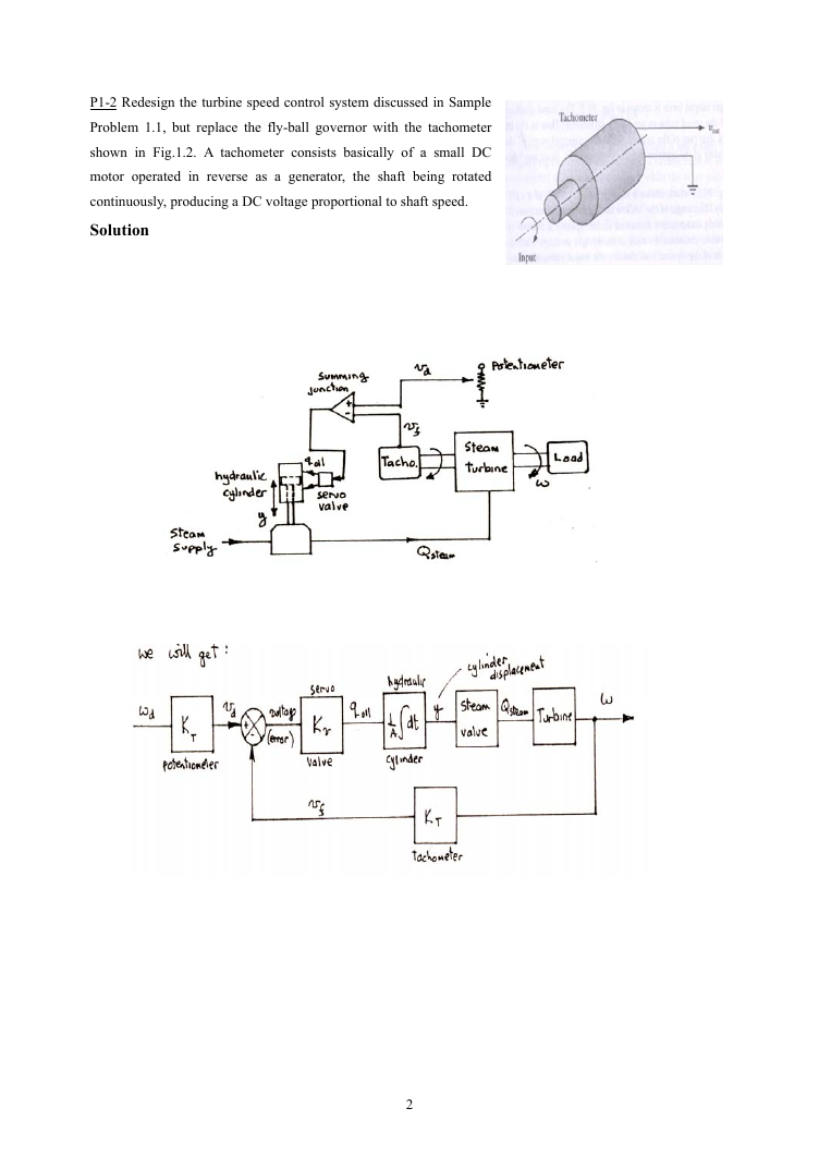
P1-2 Redesign the turbine speed control system discussed in Sample
Problem 1.1, but replace the fly-ball governor with the tachometer
shown in Fig.1.2. A tachometer consists basically of a small DC
motor operated in reverse as a generator, the shaft being rotated
continuously, producing a DC voltage proportional to shaft speed.
Solution
2
�
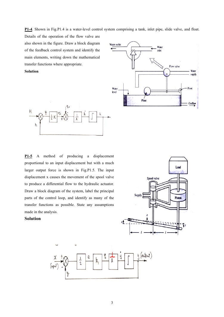
P1-4. Shown in Fig.P1.4 is a water-level control system comprising a tank, inlet pipe, slide valve, and float.
Details of the operation of the flow valve are
also shown in the figure. Draw a block diagram
of the feedback control system and identify the
main elements, writing down the mathematical
transfer functions where appropriate.
Solution
P1-5 A method of producing a displacement
proportional to an input displacement but with a much
larger output force is shown in Fig.P1.5. The input
displacement x causes the movement of the spool valve
to produce a differential flow to the hydraulic actuator.
Draw a block diagram of the system, label the principal
parts of the control loop, and identify as many of the
transfer functions as possible. State any assumptions
made in the analysis.
Solution
3
�
P2-1 A system unknown transfer function is shown in Fig.P2.1. If a unit impulse applied at the input produces
at the output a signal described by the time function
, determine the unknown transfer function.
Solution
)t(c
t3e2
−
t3e2
−
=>
)t(c
=
=
=
C
R
2
3s
+
P2-2. Find the solution of the differential equation
+
2
xd
2
dt
)t(z
When
+
dx
dt
t2e
−=
x8
=
dz
dt
+
z3
and all other initial conditions are zero.
Solution
)s(Z
=
1
2s
+
⋅
3s
+
8s
++
2
s
=
1
2s
+
⎛
⎜⎜
⎝
−
Cs
+
2
2
8s
++
⎞
⋅⎟⎟
⎠
s
C
1
=
⎛
⎜
⎜
⎜
⎜
⎝
1
2s
+
−
11
2
+
s
−
1
2
)
31
4
s(
+
⋅
1
10
⎞
⎟
⎟
⎟
⎟
⎠
)t(y
=
e1.0
−
t2
−
e1.0
−
1
2
t
⎛
⎜
⎜
⎝
cos
31
2
t
−
23
31
sin
31
2
t
⎞
⎟
⎟
⎠
P2-3 For the system shown in Fig.P2.3., determine the relationship between voltage and current, express this
relationship in the form of a transfer function and determine the current as a function of time when the voltage
is a step change from zero to 10V.
Solution
1
sLR
+
+
=
/1
Cs
Cs
+
RCs
,
+
1
2
LCs
)s(Y
=
10
s
2
LCs
Cs
+
RCs
=
+
1
−
10
10
26
s
−
10
⋅
10
+
6
−
3
1s
+
=
2
s
+
10
3
s
10
6
+
10
)t(y
=
10
−
2
2
3
−
500
t
e
sin(
3
2
1000
)t
=
.0
01154
⋅
e
−
500
t
sin(
866
)t
P2-8 For the system shown in Fig2.8 determine the closed –loop
transfer function C/R.
Solution
C
R
=
G
HG1
+
1
1
⎛
1
⎜⎜
+⋅
⎝
G
G
2
1
⎞
=⎟⎟
⎠
+
GG
2
1
HG1
+
1
P2-9 For the single input system shown in Fig2.9, find the
transfer function of output to input C/R.
Solution
GG
1
2
2
3
HGG1
+
C
R
=
HGG1
+
23
2
+
GGG
21
+
2
3
HGG
121
=>
32
HGG1
+
2
GGG
21
3
HGGGHGG
121
33
21
+
4
�
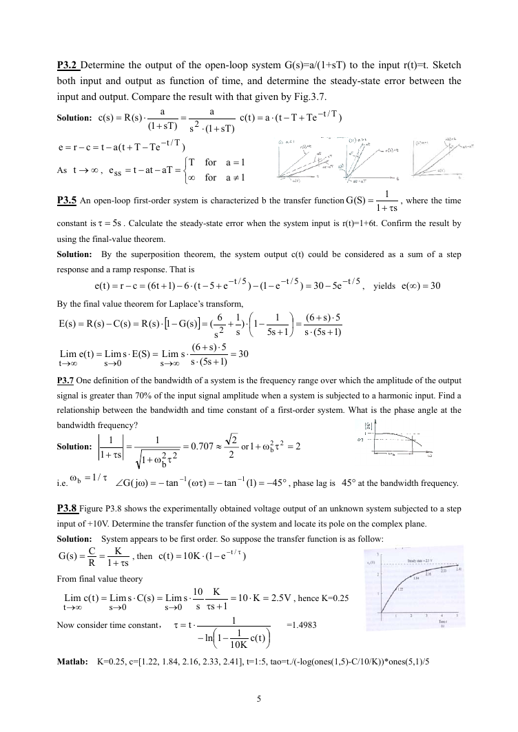
P3.2 Determine the output of the open-loop system G(s)=a/(1+sT) to the input r(t)=t. Sketch
both input and output as function of time, and determine the steady-state error between the
input and output. Compare the result with that given by Fig.3.7.
Solution:
)s(R)s(c
=
⋅
e
−=−=
c
r
t
Tt(a
−+
a
)sT1(
+
T/t−
Te
As
∞→t
,
ess
−−=
at
t
aT
=
a
)sT1(
+⋅
)t(c
+−⋅=
Tt(a
Te
T/t−
)
for
for
1a
=
1a
≠
2
=
s
)
T
⎧
⎨
∞
⎩
P3.5 An open-loop first-order system is characterized b the transfer function
)S(G
=
1
s
τ+
1
, where the time
s5=τ
. Calculate the steady-state error when the system input is r(t)=1+6t. Confirm the result by
constant is
using the final-value theorem.
Solution: By the superposition theorem, the system output c(t) could be considered as a sum of a step
response and a ramp response. That is
−
5/t
e1(
−−
−
5/t
)
=
30
−
e5
−
5/t
, yields
(e
=∞
)
30
r
c
)t(e
=−=
e5t(6)1t6(
+−⋅−+
)
By the final value theorem for Laplace’s transform,
⎛
1)
−⋅
⎜
⎝
)s(G1)s(R)s(C)s(R)s(E
[
−⋅
1
s
−
=
+
=
1
1s5
+
⎞
=⎟
⎠
5)s6(
⋅+
)1s5(s
+
⋅
]
=
6(
2
s
5)s6(s
⋅+
⋅
)1s5(s
+
⋅
⋅
0
=
=
=
30
)t(e
Lim
s
∞→
)S(EsLim
s
→
Lim
t
∞→
P3.7 One definition of the bandwidth of a system is the frequency range over which the amplitude of the output
signal is greater than 70% of the input signal amplitude when a system is subjected to a harmonic input. Find a
relationship between the bandwidth and time constant of a first-order system. What is the phase angle at the
bandwidth frequency?
1
=
.0
707
≈
or
1
=τω+
22
b
2
2
2
Solution:
1
s
τ+
1
=
=ω
b
/1
τ
i.e.
1
22
τω+
b
tan
−=ω∠
)j(G
−
1
(
−=ωτ
)
tan
−
1
)1(
45
°−=
, phase lag is
°45
at the bandwidth frequency.
P3.8 Figure P3.8 shows the experimentally obtained voltage output of an unknown system subjected to a step
input of +10V. Determine the transfer function of the system and locate its pole on the complex plane.
Solution: System appears to be first order. So suppose the transfer function is as follow:
C)s(G
R
/t τ−−⋅
e1(K10
K
s
τ+
, then
)t(c
)
=
=
=
1
From final value theory
Lim
t
∞→
)t(c
=
)s(CsLim
s
→
0
⋅
=
Now consider time constant,
⋅
sLim
0
s
→
t
⋅=τ
10
s
K
1s
+τ
=
V5.2K10
=
⋅
, hence K=0.25
1
1
K10
)t(c
⎞
⎟
⎠
−
⎛ −
1ln
⎜
⎝
=1.4983
Matlab: K=0.25, c=[1.22, 1.84, 2.16, 2.33, 2.41], t=1:5, tao=t./(-log(ones(1,5)-C/10/K))*ones(5,1)/5
5
�
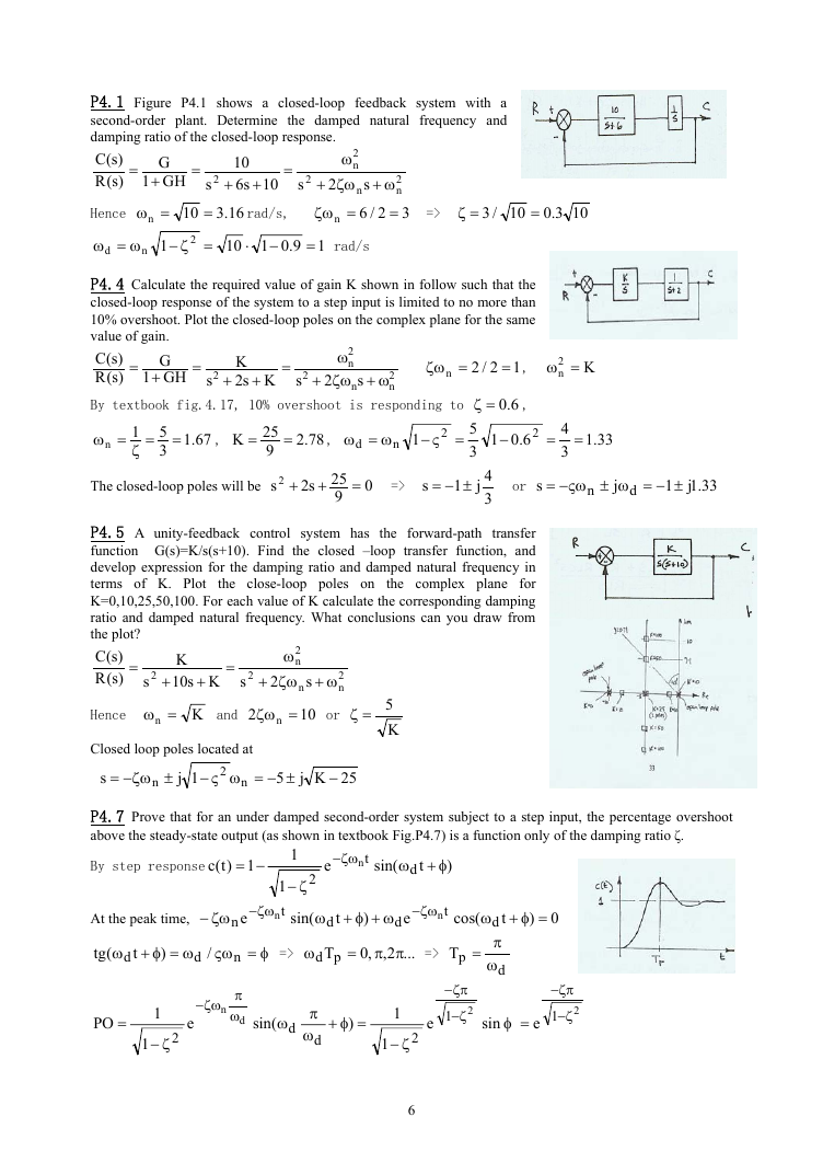
P4.1 Figure P4.1 shows a closed-loop feedback system with a
second-order plant. Determine the damped natural frequency and
damping ratio of the closed-loop response.
2
)s(C
ω
n
)s(R
2
ζω+
ζω
=
10
s6
+
16.3
2
s
ω+
n
n
2/6
=
G
GH
+
rad/s,
=ω
Hence
=>
s
=
=ζ
10
/3
=
+
=
=
3
1
s
2
2
n
n
ω=ω
d
n
1
=ζ−
10
⋅
9.01
−
=
1
rad/s
10
2
10
=
3.0
10
P4.4 Calculate the required value of gain K shown in follow such that the
closed-loop response of the system to a step input is limited to no more than
10% overshoot. Plot the closed-loop poles on the complex plane for the same
value of gain.
)s(C
)s(R
G
GH
+
K
sKs2
2
ω
n
ζω+
12/2
=
ζω
=
=
+
+
=
=
2
1
s
s
2
2
n
,
2
ω+
n
n
n
=
1
ζ
=ω
6.0=ζ
By textbook fig.4.17, 10% overshoot is responding to
5
3
4j1
3
The closed-loop poles will be
ω=ω
=ς−
±−=
25
9
25
9
=>
67.1
78.2
5
3
s 2
s2
K
,
,
=
=
=
=
+
+
1
0
s
n
d
2
6.01
−
,
K2
n =ω
2
=
4
3
=
33.1
or
s
ςω−=
n
±−=ω±
33.1j1
j
d
the close-loop poles on
P4.5 A unity-feedback control system has the forward-path transfer
function G(s)=K/s(s+10). Find the closed –loop transfer function, and
develop expression for the damping ratio and damped natural frequency in
terms of K. Plot
the complex plane for
K=0,10,25,50,100. For each value of K calculate the corresponding damping
ratio and damped natural frequency. What conclusions can you draw from
the plot?
)s(C
)s(R
K
sKs10
2
ω
n
ζω+
ω+
=
+
+
=
2
s
s
2
2
2
n
n
10
5
K
Hence
n =ω
K
and
2
ζω
n =
or
=ζ
Closed loop poles located at
s
ζω−=
1j
±
2
n
n
±−=ως−
25Kj5
−
P4.7 Prove that for an under damped second-order system subject to a step input, the percentage overshoot
above the steady-state output (as shown in textbook Fig.P4.7) is a function only of the damping ratio ζ.
By step response
1)t(c
−=
At the peak time,
ζω−
e
n
ζω−
1
t
n
1
2
ζ−
ζω−
t
n
e
sin(
)
φ+ω
t
d
sin(
ω+φ+ω
)
t
ζω−
t
n
e
d
cos(
=φ+ω
)
0
d
Tpd
t
d
π
ω
d
(tg
ω=φ+ω
)
t
d
/
ςω
n
d
φ=
=>
ω
=
,0
2,
ππ
...
=>
pT
=
ζω−
n
e
π
ω
d
PO
=
1
2
1
ζ−
sin(
ω
d
π
ω
d
=φ+
)
1
2
1
ζ−
e
ζπ−
2
1
ζ−
ζπ−
2
1
ζ−
sin
=φ
e
6
�
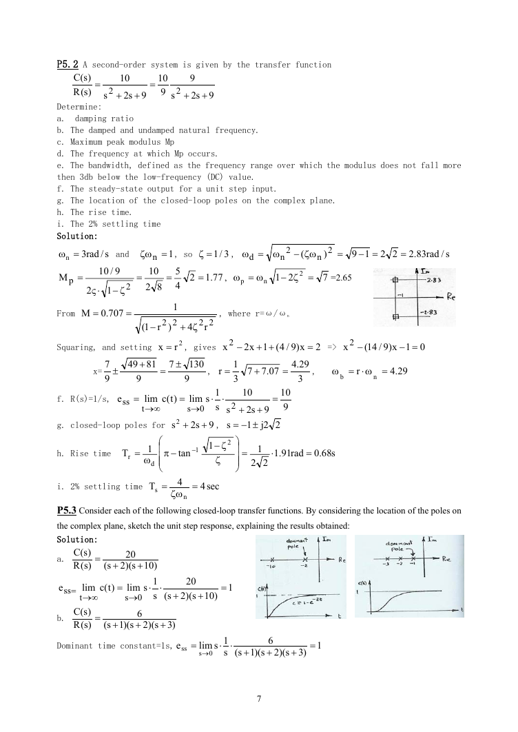
P5.2 A second-order system is given by the transfer function
)s(C
)s(R
=
10
9s2
+
+
=
10
9
2
2
9
9s2
+
s
+
s
Determine:
a. damping ratio
b. The damped and undamped natural frequency.
c. Maximum peak modulus Mp
d. The frequency at which Mp occurs.
e. The bandwidth, defined as the frequency range over which the modulus does not fall more
then 3db below the low-frequency (DC) value.
f. The steady-state output for a unit step input.
g. The location of the closed-loop poles on the complex plane.
h. The rise time.
i. The 2% settling time
Solution:
s/
9/10
ω=ω
3/1=ζ
n =ω
ζω−
19
=−
and
rad3
83.2
22
rad
ζω
s/
,
=
=
1
2
n
2
n
d
)
(
=
77.1
,
ω=ω
p
n
21
=ζ−
2
7
=2.65
n =
10
82
=
, so
5
4
2
=
M
p
=
2
⋅ς
1
ζ−
2
, where r=ω/ωn
22
r
x 2
−
1
3
=
++
x)9/4(1x2
=
29.4
3
07.77
+
=
2
=>
x 2
−
01x)9/14(
=−
,
=ω⋅=ω
r
29.4
b
n
From
.0M
=
707
=
r1(
−
1
22
)
Squaring, and setting
81
x=
±
7
9
49
+
9
x =
7
=
f. R(s)=1/s,
e
ss
=
)t(c
lim
t
∞→
=
g. closed-loop poles for
s2
4
ζ+
2r
±
,
, gives
130
9
r
1s
lim
⋅
s
0
s
→
, 9s2
+
+
⋅
h. Rise time
T
r
=
1
ω
d
i. 2% settling time
T
s
⎛
⎜
⎜⎜
⎝
=
1
1
−
tan
−π
ζ−
ζ
4
ζω
n
=
sec4
10
9
s
s
2
2
=
10
9s2
+
+
22j1
±−=
⎞
⎟
⎟⎟
⎠
1
22
=
⋅
91.1
rad
=
s68.0
P5.3 Consider each of the following closed-loop transfer functions. By considering the location of the poles on
the complex plane, sketch the unit step response, explaining the results obtained:
Solution:
a.
e
ss
b.
)s(C
)s(R
=
20
s)(2s(
+
+
)t(c
=
=
lim
t
∞→
)s(C
)s(R
=
lim
0
s
→
6
+
)3s)(2s)(1s(
+
+
)10
1s
⋅
s
⋅
20
s)(2s(
+
+
)10
=
1
Dominant time constant=1s,
e
ss
=
lim
s
0
→
1s
⋅
s
⋅
6
+
)3s)(2s)(1s(
+
+
=
1
7
�
c.
Poles:
=
)s(C
)s(R
s
−=
=ω
n
from Fig4.7,
1s
⋅
s
=
e
ss
⋅
lim
0
s
→
)s(C
)s(R
=
d.
Solving
2
s
9
3s
++
5.0j5.0
±
,3
=ζ
PO
=
9
3s
++
10
+
+
5s4
s
2
2
11
732.1/5.0
,%35
c
Δ
=
3
+
)5.0s)(5s4
=+
0
gives
=ζ
sin
=θ
=
54.0
=
89.0
s(
s 2
+
2
5
=
=
289.0
05.4
s
±−=
2
j
No overshoot, however, real axis pole will dominate with a time constant at 2s.ess=10/2.5=4
e.
)s(C
)s(R
=
Solving
gives
1
2
+
=+
s)(5s(
+
s2
5s2
+
2j1
s
±−=
)5s2
+
0
=ζ
sin
=θ
1
5
=
45.0
The complex pair will dominate the real axis pole,
ess=1/25=0.04
=
f.
)s(C
)s(R
Solving
Solving
100
2
s)(13
2
s(
+
+
s6
+
+
s2
13
s6
+
s2
40
s12
+
pair closer
+
)40
s12
+
j23
s
±−=
s
j26
±−=
to im
aginary axis will
,gives
, gives
Complex
dominate those further away.
ζ
dom
=
3
13
=
83.0
High damping, no or little overshoot, Steady state output=100/(13*40)=0.192
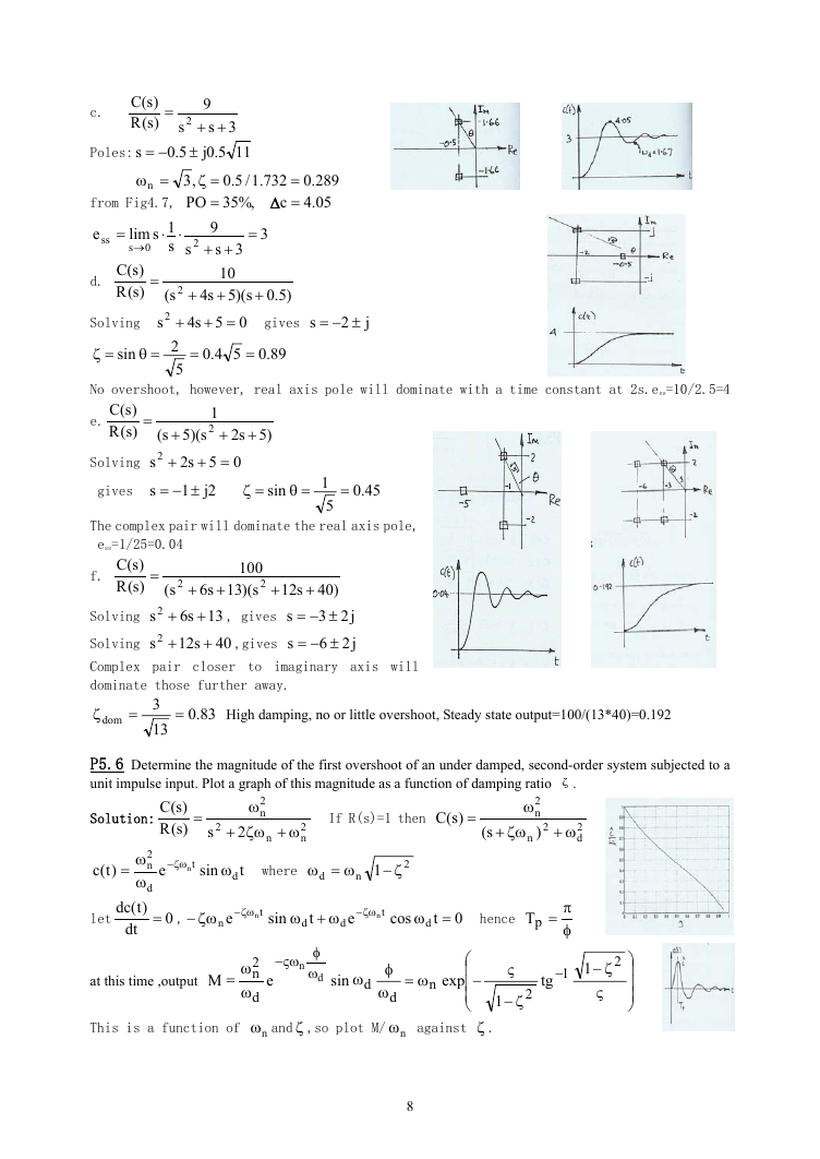
P5.6 Determine the magnitude of the first overshoot of an under damped, second-order system subjected to a
unit impulse input. Plot a graph of this magnitude as a function of damping ratio ζ.
Solution:
)s(C
)s(R
=
2
ω
n
ζω+
2
2
s
ω+
2
n
n
If R(s)=1 then
)s(C
=
ω
ζω+
n
2
n
)
s(
2
ω+
2
d
)t(c
let
2
n
=
ω
ω
d
)t(dc
dt
ζω−
t
n
e
sin
ω
t
d
where
ω=ω
d
n
2
1 ζ−
= ,
0
ζω−
e
n
ζω−
t
n
sin
ω+ω
t
d
ζω−
t
n
e
d
cos
=ω
t
d
0
hence
=pT
π
φ
at this time ,output
M
=
ςω−
n
φ
ω
d
ω
ω
2
n
d
e
sin
ω
d
φ
ω
d
This is a functi
on of
nω and ζ ,so plot M/
nω
−
ω=
n
⎛
⎜
exp
⎜
⎜
⎝
against
ζ
.
1
−
tg
ς
2
1
ζ−
2
ζ
1
−
ς
⎞
⎟
⎟
⎟
⎠
8
�




 2023年江西萍乡中考道德与法治真题及答案.doc
 2012年重庆南川中考生物真题及答案.doc
 2013年江西师范大学地理学综合及文艺理论基础考研真题.doc
 2020年四川甘孜小升初语文真题及答案I卷.doc
 2020年注册岩土工程师专业基础考试真题及答案.doc
 2023-2024学年福建省厦门市九年级上学期数学月考试题及答案.doc
 2021-2022学年辽宁省沈阳市大东区九年级上学期语文期末试题及答案.doc
 2022-2023学年北京东城区初三第一学期物理期末试卷及答案.doc
 2018上半年江西教师资格初中地理学科知识与教学能力真题及答案.doc
 2012年河北国家公务员申论考试真题及答案-省级.doc
 2020-2021学年江苏省扬州市江都区邵樊片九年级上学期数学第一次质量检测试题及答案.doc
 2022下半年黑龙江教师资格证中学综合素质真题及答案.doc