logo资料库

PLECS, User Manual, Version 4.1.pdf

第1页 / 共742页
第2页 / 共742页
第3页 / 共742页
第4页 / 共742页
第5页 / 共742页
第6页 / 共742页
第7页 / 共742页
第8页 / 共742页
资料共742页,剩余部分请下载后查看
Contents
Before You Begin
Installing PLECS Blockset
Installation on Microsoft Windows
Installation on Mac OS X
Installation on Linux
Licensing
Configuring the MATLAB Search Path
Configuring PLECS
Installing Different Versions of PLECS Blockset in Parallel
Uninstalling PLECS Blockset
Installing PLECS Standalone
Installation on Microsoft Windows
Installation on Mac OS X
Installation on Linux
Licensing
License File Location
Network Licensing
What's New in Version 4.1
Major New Features
Further Enhancements
Introduction
Concepts of PLECS
Integration into Simulink
Ideal Switches
Getting Started
Getting Started with PLECS Blockset
A Simple Passive Network
Buck Converter
Getting Started with PLECS Standalone
A Simple Passive Network
Buck Converter
How PLECS Works
Modeling Dynamic Systems
System Equations
Block Diagrams
Physical Models
Simulating Dynamic Systems
Model Initialization
Model Execution
Fixed-Step Simulation
Sampled Data Systems
Sample Times
Sample Time Inheritance
Multirate Systems
Troubleshooting
Using PLECS
Configuring PLECS
General
Libraries
Thermal
Scope Colors
Update
Coder
Installing Extensions
Creating a New Circuit with PLECS Blockset
Customizing the Circuit Block
Using the Library Browser
Components
Specifying Component Parameters
Displaying Parameters in the Schematic
Changing Parameters of Multiple Components
Changing Parameters During a Simulation
Changing Component Names
Changing the Orientation of Components
Getting Component Help
Libraries
Creating a New Library in PLECS Blockset
Creating a New Library in PLECS Standalone
Creating a Library Reference
Updating a Library Reference
Breaking a Library Reference
Connections
Wires
Signals
Creating Branches
Annotations
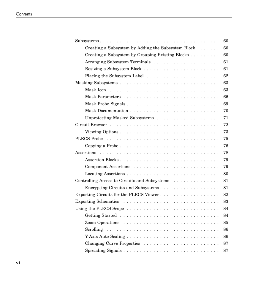
Subsystems
Creating a Subsystem by Adding the Subsystem Block
Creating a Subsystem by Grouping Existing Blocks
Arranging Subsystem Terminals
Resizing a Subsystem Block
Placing the Subsystem Label
Masking Subsystems
Mask Icon
Mask Parameters
Mask Probe Signals
Mask Documentation
Unprotecting Masked Subsystems
Circuit Browser
Viewing Options
PLECS Probe
Copying a Probe
Assertions
Assertion Blocks
Component Assertions
Locating Assertions
Controlling Access to Circuits and Subsystems
Encrypting Circuits and Subsystems
Exporting Circuits for the PLECS Viewer
Exporting Schematics
Using the PLECS Scope
Getting Started
Zoom Operations
Scrolling
Y-Axis Auto-Scaling
Changing Curve Properties
Spreading Signals
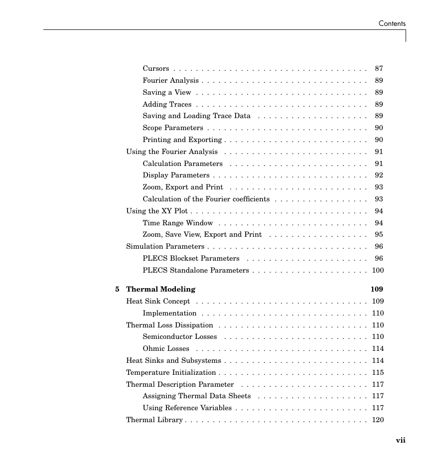
Cursors
Fourier Analysis
Saving a View
Adding Traces
Saving and Loading Trace Data
Scope Parameters
Printing and Exporting
Using the Fourier Analysis
Calculation Parameters
Display Parameters
Zoom, Export and Print
Calculation of the Fourier coefficients
Using the XY Plot
Time Range Window
Zoom, Save View, Export and Print
Simulation Parameters
PLECS Blockset Parameters
PLECS Standalone Parameters
Thermal Modeling
Heat Sink Concept
Implementation
Thermal Loss Dissipation
Semiconductor Losses
Ohmic Losses
Heat Sinks and Subsystems
Temperature Initialization
Thermal Description Parameter
Assigning Thermal Data Sheets
Using Reference Variables
Thermal Library
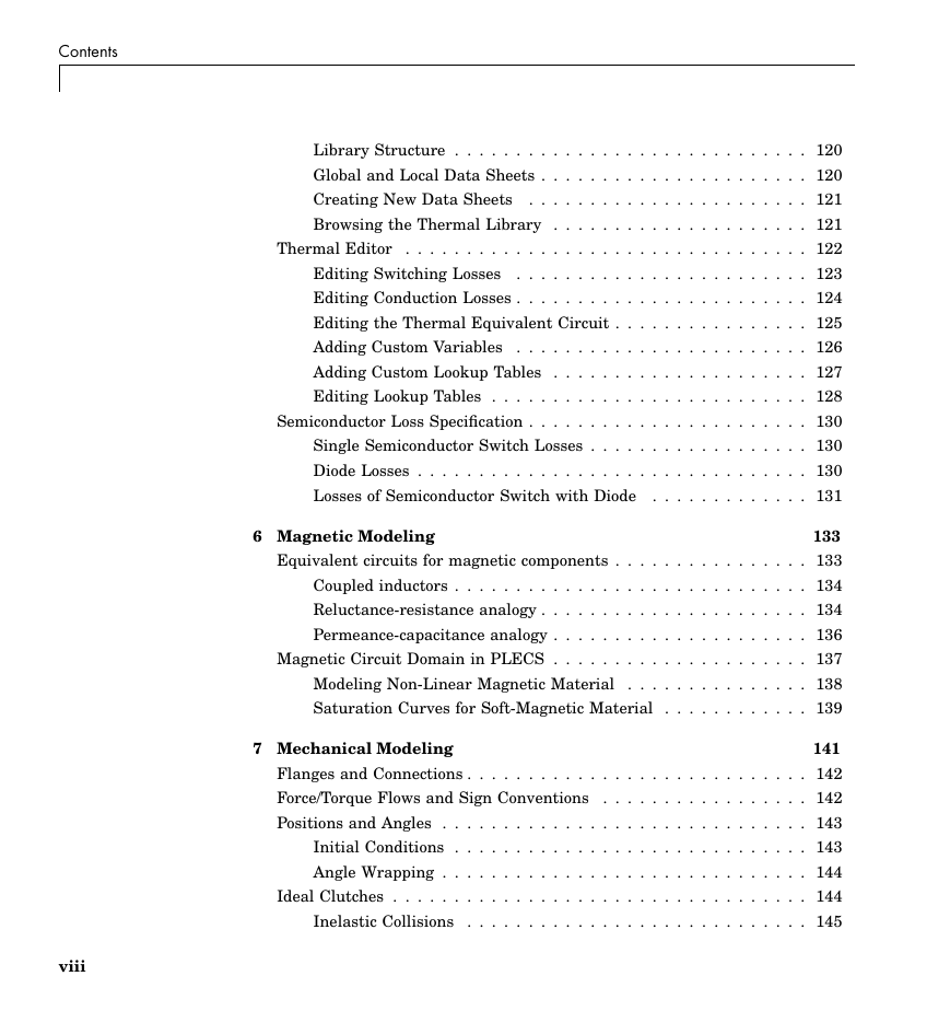
Library Structure
Global and Local Data Sheets
Creating New Data Sheets
Browsing the Thermal Library
Thermal Editor
Editing Switching Losses
Editing Conduction Losses
Editing the Thermal Equivalent Circuit
Adding Custom Variables
Adding Custom Lookup Tables
Editing Lookup Tables
Semiconductor Loss Specification
Single Semiconductor Switch Losses
Diode Losses
Losses of Semiconductor Switch with Diode
Magnetic Modeling
Equivalent circuits for magnetic components
Coupled inductors
Reluctance-resistance analogy
Permeance-capacitance analogy
Magnetic Circuit Domain in PLECS
Modeling Non-Linear Magnetic Material
Saturation Curves for Soft-Magnetic Material
Mechanical Modeling
Flanges and Connections
Force/Torque Flows and Sign Conventions
Positions and Angles
Initial Conditions
Angle Wrapping
Ideal Clutches
Inelastic Collisions
Analysis Tools
Steady-State Analysis
Algorithm
Fast Jacobian Calculation for Thermal States
Non-periodic Case
Limitations
Reference
AC Analysis
Impulse Response Analysis
Algorithm
Compensation for Discrete Pulse
Reference
Multitone Analysis
Algorithm
Remarks
References
Usage in PLECS Standalone
Steady-State Analysis
AC Sweep
Impulse Response Analysis
Multitone Analysis
Extraction of State-Space Matrices
Application Example
Usage in PLECS Blockset
Steady-State Analysis
AC Sweep / Loop Gain Analysis
Impulse Response Analysis
Multitone / Loop Gain Analysis
Extraction of State-Space Matrices
Application Example
C-Scripts
How C-Scripts Work
C-Script Functions
Modeling Discontinuities
Sample Time
User Parameters
Runtime Checks
C-Script Examples
A Simple Function – Times Two
Discrete States – Sampled Delay
Continuous States – Integrator
Event Handling – Wrapping Integrator
Piecewise Smooth Functions – Saturation
Multiple Sample Times – Turn-on Delay
C-Script Macros
Deprecated Macros
State Machines
Working with State Machines
Working with States
Working with Transitions
Working with Junctions
Working with Annotations
State Machine Configuration
State Machine Execution
Transition Evaluation
Trigger Types
Trigger Lifetime
Execution of Hierarchical State Machines
State Machine Examples
Oven Control
Constant On-Time Control
Simulation Scripts
Command Line Interface in PLECS Blockset
Simulation Scripts in PLECS Standalone
Overview of PLECS Scripting Extensions
Example Script
XML-RPC Interface in PLECS Standalone
Establishing an XML-RPC Connection to PLECS
Overview of XML-RPC Commands
Example Script
Scripted Simulation and Analysis Options
Code Generation
Code Generation for Physical Systems
Reducing the Code Size
Maximum Number of Switches
Handling Naturally Commutated Devices
Unsupported Components
Code Generation with PLECS Standalone
Generating Code
Simulating a Subsystem in CodeGen Mode
Code Generation with PLECS Blockset
Standalone Code Generation
Integration with Simulink Coder
Simulink Coder Options
Code Generation Targets
Real-Time Target
Rapid Simulation Target
Processor-in-the-Loop
Motivation
How PIL Works
PIL Modes
Configuring PLECS for PIL
Target Manager
Communication Links
PIL Block
Components by Category
System
Assertions
Control
Sources
Math
Continuous
Delays
Discontinuous
Discrete
Filters
Functions & Tables
Logical
Modulators
Transformations
State Machine
Small Signal Analysis
Electrical
Sources
Meters
Passive Components
Power Semiconductors
Power Modules
Switches
Transformers
Machines
Converters
Electronics
Model Settings
Thermal
Magnetic
Mechanical
Translational
Rotational
Additional Simulink Blocks
Component Reference
1D Look-Up Table
2D Look-Up Table
2-Pulse Generator
3D Look-Up Table
3-Phase Overmodulation
6-Pulse Generator
Abs
Algebraic Constraint
Ambient Temperature
Air Gap
Ammeter
Angle Sensor
Assert Dynamic Lower Limit
Assert Dynamic Range
Assert Dynamic Upper Limit
Assertion
Assert Lower Limit
Assert Range
Assert Upper Limit
Blanking Time
Blanking Time (3-Level)
Breaker
Brushless DC Machine
Brushless DC Machine (Simple)
C-Script
Capacitor
Clock
Combinatorial Logic
Comparator
Compare to Constant
Configurable Subsystem
Constant
Constant Heat Flow
Constant Temperature
Controlled Heat Flow
Controlled Temperature
Current Source (Controlled)
Current Source AC
Current Source DC
D Flip-flop
DC Machine
Dead Zone
Delay
Diode
Diode with Reverse Recovery
Diode Rectifier (3ph)
Discrete Fourier Transform
Discrete Integrator
Discrete Mean Value
Discrete RMS Value
Discrete State Space
Discrete Total Harmonic Distortion
Discrete Transfer Function
Display
DLL
Double Switch
Edge Detection
Electrical Algebraic Component
Electrical Ground
Electrical Label
Electrical Model Settings
Electrical Port
Enable
Flux Rate Meter
Force (Constant)
Force (Controlled)
Force Sensor
Fourier Series
Function
Gain
Gear
GTO
GTO (Reverse Conducting)
Heat Flow Meter
Heat Sink
Hit Crossing
Hysteretic Core
Ideal 3-Level Converter (3ph)
Ideal Converter (3ph)
Ideal Transformer
IGBT
IGBT 3-Level Converter (3ph)
IGBT 3-Level Half Bridge (NPC)
IGBT Chopper (High-Side Switch)
IGBT Chopper (High-Side Switch with Reverse Diode)
IGBT Chopper (Low-Side Switch)
IGBT Chopper (Low-Side Switch with Reverse Diode)
IGBT Converter (3ph)
IGBT Full Bridges (Series Connected)
IGBT Half Bridge
IGBT Half Bridges (Low-/High-Side Connected)
IGBT with Diode
IGBT with Limited di/dt
IGCT (Reverse Blocking)
IGCT (Reverse Conducting)
Induction Machine (Slip Ring)
Induction Machine (Open Stator Windings)
Induction Machine (Squirrel Cage)
Induction Machine with Saturation
Inductor
Inertia
Initial Condition
Integrator
JK Flip-flop
Leakage Flux Path
Linear Core
Linear Transformer (2 Windings)
Linear Transformer (3 Windings)
Logical Operator
Magnetic Permeance
Magnetic Port
Magnetic Resistance
Manual Double Switch
Manual Signal Switch
Manual Switch
Manual Triple Switch
Mass
Math Function
Memory
Meter (3-Phase)
Minimum / Maximum
MMF Meter
MMF Source (Constant)
MMF Source (Controlled)
Monoflop
MOSFET
MOSFET Converter (3ph)
MOSFET with Diode
MOSFET with Limited di/dt
Moving Average
Mutual Inductor
Mutual Inductance (2 Windings)
Mutual Inductance (3 Windings)
Non-Excited Synchronous Machine
Offset
Op-Amp
Op-Amp with Limited Output
Pause / Stop
Peak Current Controller
Periodic Average
Periodic Impulse Average
Permanent Magnet Synchronous Machine
Pi-Section Line
Piece-wise Linear Resistor
Planetary Gear Set
Polar to Rectangular
Position Sensor
Product
Pulse Delay
Pulse Generator
Quantizer
Rack and Pinion
Ramp
Random Numbers
Rate Limiter
Rectangular to Polar
Relational Operator
Relay
Resistor
Rotational Algebraic Component
Rotational Backlash
Rotational Clutch
Rotational Damper
Rotational Friction
Rotational Hard Stop
Rotational Model Settings
Rotational Port
Rotational Reference
Rotational Speed (Constant)
Rotational Speed (Controlled)
Rotational Speed Sensor
Rounding
Saturable Capacitor
Saturable Core
Saturable Inductor
Saturable Transformers
Saturation
Sawtooth PWM
Sawtooth PWM (3-Level)
Scope
Set/Reset Switch
Signal Demultiplexer
Signal From
Signal Goto
Signal Inport
Signal Multiplexer
Signal Outport
Signal Selector
Signal Switch
Signum
Sine Wave
Small Signal Gain
Small Signal Perturbation
Small Signal Response
Space Vector PWM
Space Vector PWM (3-Level)
SR Flip-flop
State Machine
State Space
Step
Subsystem
Sum
Switch
Switched Reluctance Machine
Symmetrical PWM
Symmetrical PWM (3-Level)
Synchronous Machine (Round Rotor)
Synchronous Machine (Salient Pole)
Synchronous Reluctance Machine
Thermal Capacitor
Thermal Chain
Thermal Ground
Thermal Model Settings
Thermal Port
Thermal Resistor
Thermometer
Thyristor
Thyristor Rectifier/Inverter
Thyristor with Reverse Recovery
To File
Torque (Constant)
Torque (Controlled)
Torque Sensor
Torsion Spring
Transfer Function
Transformation 3ph->RRF
Transformation 3ph->SRF
Transformation RRF->3ph
Transformation RRF->SRF
Transformation SRF->3ph
Transformation SRF->RRF
Transformers (3ph, 2 Windings)
Transformers (3ph, 3 Windings)
Translational Algebraic Component
Translational Backlash
Translational Clutch
Translational Damper
Translational Friction
Translational Hard Stop
Translational Model Settings
Translational Port
Translational Reference
Translational Speed (Constant)
Translational Speed (Controlled)
Translational Speed Sensor
Translational Spring
Transmission Line (3ph)
Transport Delay
TRIAC
Triangular Wave Generator
Trigonometric Function
Triple Switch
Trigger
Turn-on Delay
Variable Capacitor
Variable Inductor
Variable Magnetic Permeance
Variable Resistor
Variable Resistor with Constant Capacitor
Variable Resistor with Constant Inductor
Variable Resistor with Variable Capacitor
Variable Resistor with Variable Inductor
Voltage Source (Controlled)
Voltage Source AC
Voltage Source AC (3-Phase)
Voltage Source DC
Voltmeter
White Noise
Winding
Wire Multiplexer
Wire Selector
XY Plot
Zener Diode
Zero Order Hold
Additional Simulink Blocks
AC Sweep
Discrete Analysis
Impulse Response Analysis
Loop Gain Analysis (AC Sweep)
Loop Gain Analysis (Multitone)
Modulators
Multitone Analysis
Steady-State Analysis
Timer
Transformations

THE SIMULATION PLATFORM FOR POWER ELECTRONIC SYSTEMS User Manual Version 4.1 electrical engineering softwarePlexim GmbH info@plexim.com www.plexim.complecs User Manual Version 3.4
How to Contact Plexim:  u @ +41 44 533 51 00 +41 44 533 51 01 Plexim GmbH Technoparkstrasse 1 8005 Zurich Switzerland info@plexim.com http://www.plexim.com Phone Fax Mail Email Web PLECS User Manual © 2002–2018 by Plexim GmbH The software PLECS described in this manual is furnished under a license agreement. The software may be used or copied only under the terms of the license agreement. No part of this manual may be photocopied or reproduced in any form without prior written consent from Plexim GmbH. PLECS is a registered trademark of Plexim GmbH. MATLAB, Simulink and Simulink Coder are registered trademarks of The MathWorks, Inc. Other product or brand names are trademarks or registered trademarks of their re- spective holders.
Contents Contents Before You Begin Installing PLECS Blockset . . . . . . . . . . . . . . . . . . . . . . . . . . Installation on Microsoft Windows . . . . . . . . . . . . . . . . . . . Installation on Mac OS X . . . . . . . . . . . . . . . . . . . . . . . . Installation on Linux . . . . . . . . . . . . . . . . . . . . . . . . . . . Licensing . . . . . . . . . . . . . . . . . . . . . . . . . . . . . . . . . . Configuring the MATLAB Search Path . . . . . . . . . . . . . . . . Configuring PLECS . . . . . . . . . . . . . . . . . . . . . . . . . . . . Installing Different Versions of PLECS Blockset in Parallel . . . . Uninstalling PLECS Blockset . . . . . . . . . . . . . . . . . . . . . . Installing PLECS Standalone . . . . . . . . . . . . . . . . . . . . . . . . . Installation on Microsoft Windows . . . . . . . . . . . . . . . . . . . Installation on Mac OS X . . . . . . . . . . . . . . . . . . . . . . . . Installation on Linux . . . . . . . . . . . . . . . . . . . . . . . . . . . Licensing . . . . . . . . . . . . . . . . . . . . . . . . . . . . . . . . . . License File Location . . . . . . . . . . . . . . . . . . . . . . . . . . . . . . Network Licensing . . . . . . . . . . . . . . . . . . . . . . . . . . . . . . . What’s New in Version 4.1 . . . . . . . . . . . . . . . . . . . . . . . . . . . Major New Features . . . . . . . . . . . . . . . . . . . . . . . . . . . Further Enhancements . . . . . . . . . . . . . . . . . . . . . . . . . . iii 1 1 1 1 2 2 3 3 4 4 5 5 5 5 6 6 7 8 8 8
Contents iv 1 Introduction Concepts of PLECS . . . . . . . . . . . . . . . . . . . . . . . . . . . . . . . Integration into Simulink . . . . . . . . . . . . . . . . . . . . . . . . 9 9 9 Ideal Switches . . . . . . . . . . . . . . . . . . . . . . . . . . . . . . . 10 2 Getting Started Getting Started with PLECS Blockset . . . . . . . . . . . . . . . . . . . . A Simple Passive Network . . . . . . . . . . . . . . . . . . . . . . . . Buck Converter . . . . . . . . . . . . . . . . . . . . . . . . . . . . . . Getting Started with PLECS Standalone . . . . . . . . . . . . . . . . . . A Simple Passive Network . . . . . . . . . . . . . . . . . . . . . . . . Buck Converter . . . . . . . . . . . . . . . . . . . . . . . . . . . . . . 3 How PLECS Works Modeling Dynamic Systems . . . . . . . . . . . . . . . . . . . . . . . . . . System Equations . . . . . . . . . . . . . . . . . . . . . . . . . . . . . Block Diagrams . . . . . . . . . . . . . . . . . . . . . . . . . . . . . . Physical Models . . . . . . . . . . . . . . . . . . . . . . . . . . . . . . Simulating Dynamic Systems . . . . . . . . . . . . . . . . . . . . . . . . . Model Initialization . . . . . . . . . . . . . . . . . . . . . . . . . . . . Model Execution . . . . . . . . . . . . . . . . . . . . . . . . . . . . . . Fixed-Step Simulation . . . . . . . . . . . . . . . . . . . . . . . . . . Sampled Data Systems . . . . . . . . . . . . . . . . . . . . . . . . . . . . . Sample Times . . . . . . . . . . . . . . . . . . . . . . . . . . . . . . . Sample Time Inheritance . . . . . . . . . . . . . . . . . . . . . . . . Multirate Systems . . . . . . . . . . . . . . . . . . . . . . . . . . . . Troubleshooting . . . . . . . . . . . . . . . . . . . . . . . . . . . . . . 13 13 13 19 22 22 26 29 29 30 30 31 31 32 35 37 40 40 41 42 42
Contents 4 Using PLECS Configuring PLECS . . . . . . . . . . . . . . . . . . . . . . . . . . . . . . . General . . . . . . . . . . . . . . . . . . . . . . . . . . . . . . . . . . . Libraries . . . . . . . . . . . . . . . . . . . . . . . . . . . . . . . . . . Thermal . . . . . . . . . . . . . . . . . . . . . . . . . . . . . . . . . . Scope Colors . . . . . . . . . . . . . . . . . . . . . . . . . . . . . . . . Update . . . . . . . . . . . . . . . . . . . . . . . . . . . . . . . . . . . Coder . . . . . . . . . . . . . . . . . . . . . . . . . . . . . . . . . . . . Installing Extensions . . . . . . . . . . . . . . . . . . . . . . . . . . . . . . Creating a New Circuit with PLECS Blockset . . . . . . . . . . . . . . . Customizing the Circuit Block . . . . . . . . . . . . . . . . . . . . . Using the Library Browser . . . . . . . . . . . . . . . . . . . . . . . . . . Components . . . . . . . . . . . . . . . . . . . . . . . . . . . . . . . . . . . Specifying Component Parameters . . . . . . . . . . . . . . . . . . . Displaying Parameters in the Schematic . . . . . . . . . . . . . . . Changing Parameters of Multiple Components . . . . . . . . . . . . Changing Parameters During a Simulation . . . . . . . . . . . . . . Changing Component Names . . . . . . . . . . . . . . . . . . . . . . Changing the Orientation of Components . . . . . . . . . . . . . . . Getting Component Help . . . . . . . . . . . . . . . . . . . . . . . . . Libraries . . . . . . . . . . . . . . . . . . . . . . . . . . . . . . . . . . . . . . . . . . . . . . . . . . Creating a New Library in PLECS Blockset Creating a New Library in PLECS Standalone . . . . . . . . . . . . Creating a Library Reference . . . . . . . . . . . . . . . . . . . . . . Updating a Library Reference . . . . . . . . . . . . . . . . . . . . . . Breaking a Library Reference . . . . . . . . . . . . . . . . . . . . . . Connections . . . . . . . . . . . . . . . . . . . . . . . . . . . . . . . . . . . Wires . . . . . . . . . . . . . . . . . . . . . . . . . . . . . . . . . . . . Signals . . . . . . . . . . . . . . . . . . . . . . . . . . . . . . . . . . . Creating Branches . . . . . . . . . . . . . . . . . . . . . . . . . . . . Annotations . . . . . . . . . . . . . . . . . . . . . . . . . . . . . . . . . . . 45 45 45 46 47 47 47 48 49 49 50 52 54 54 55 55 55 56 56 56 57 57 57 57 58 58 59 59 59 59 59 v
Contents vi Subsystems . . . . . . . . . . . . . . . . . . . . . . . . . . . . . . . . . . . . Creating a Subsystem by Adding the Subsystem Block . . . . . . . Creating a Subsystem by Grouping Existing Blocks . . . . . . . . . Arranging Subsystem Terminals . . . . . . . . . . . . . . . . . . . . Resizing a Subsystem Block . . . . . . . . . . . . . . . . . . . . . . . Placing the Subsystem Label . . . . . . . . . . . . . . . . . . . . . . Masking Subsystems . . . . . . . . . . . . . . . . . . . . . . . . . . . . . . Mask Icon . . . . . . . . . . . . . . . . . . . . . . . . . . . . . . . . . Mask Parameters . . . . . . . . . . . . . . . . . . . . . . . . . . . . . Mask Probe Signals . . . . . . . . . . . . . . . . . . . . . . . . . . . . Mask Documentation . . . . . . . . . . . . . . . . . . . . . . . . . . . Unprotecting Masked Subsystems . . . . . . . . . . . . . . . . . . . Circuit Browser . . . . . . . . . . . . . . . . . . . . . . . . . . . . . . . . . Viewing Options . . . . . . . . . . . . . . . . . . . . . . . . . . . . . . PLECS Probe . . . . . . . . . . . . . . . . . . . . . . . . . . . . . . . . . . Copying a Probe . . . . . . . . . . . . . . . . . . . . . . . . . . . . . . Assertions . . . . . . . . . . . . . . . . . . . . . . . . . . . . . . . . . . . . Assertion Blocks . . . . . . . . . . . . . . . . . . . . . . . . . . . . . . Component Assertions . . . . . . . . . . . . . . . . . . . . . . . . . . Locating Assertions . . . . . . . . . . . . . . . . . . . . . . . . . . . . Controlling Access to Circuits and Subsystems . . . . . . . . . . . . . . . Encrypting Circuits and Subsystems . . . . . . . . . . . . . . . . . . Exporting Circuits for the PLECS Viewer . . . . . . . . . . . . . . . . . . Exporting Schematics . . . . . . . . . . . . . . . . . . . . . . . . . . . . . Using the PLECS Scope . . . . . . . . . . . . . . . . . . . . . . . . . . . . Getting Started . . . . . . . . . . . . . . . . . . . . . . . . . . . . . . Zoom Operations . . . . . . . . . . . . . . . . . . . . . . . . . . . . . Scrolling . . . . . . . . . . . . . . . . . . . . . . . . . . . . . . . . . . Y-Axis Auto-Scaling . . . . . . . . . . . . . . . . . . . . . . . . . . . . Changing Curve Properties . . . . . . . . . . . . . . . . . . . . . . . Spreading Signals . . . . . . . . . . . . . . . . . . . . . . . . . . . . . 60 60 60 61 61 62 63 63 66 69 70 71 72 73 75 76 78 79 79 80 81 81 82 83 84 84 85 86 86 87 87
Contents Cursors . . . . . . . . . . . . . . . . . . . . . . . . . . . . . . . . . . . Fourier Analysis . . . . . . . . . . . . . . . . . . . . . . . . . . . . . . Saving a View . . . . . . . . . . . . . . . . . . . . . . . . . . . . . . . Adding Traces . . . . . . . . . . . . . . . . . . . . . . . . . . . . . . . Saving and Loading Trace Data . . . . . . . . . . . . . . . . . . . . Scope Parameters . . . . . . . . . . . . . . . . . . . . . . . . . . . . . Printing and Exporting . . . . . . . . . . . . . . . . . . . . . . . . . . Using the Fourier Analysis . . . . . . . . . . . . . . . . . . . . . . . . . . Calculation Parameters . . . . . . . . . . . . . . . . . . . . . . . . . Display Parameters . . . . . . . . . . . . . . . . . . . . . . . . . . . . Zoom, Export and Print . . . . . . . . . . . . . . . . . . . . . . . . . Calculation of the Fourier coefficients . . . . . . . . . . . . . . . . . Using the XY Plot . . . . . . . . . . . . . . . . . . . . . . . . . . . . . . . . Time Range Window . . . . . . . . . . . . . . . . . . . . . . . . . . . Zoom, Save View, Export and Print . . . . . . . . . . . . . . . . . . Simulation Parameters . . . . . . . . . . . . . . . . . . . . . . . . . . . . . . . . . . . . . . . . . . . . . . . . . . . 87 89 89 89 89 90 90 91 91 92 93 93 94 94 95 96 PLECS Blockset Parameters 96 PLECS Standalone Parameters . . . . . . . . . . . . . . . . . . . . . 100 5 Thermal Modeling Heat Sink Concept 109 . . . . . . . . . . . . . . . . . . . . . . . . . . . . . . . 109 Implementation . . . . . . . . . . . . . . . . . . . . . . . . . . . . . . 110 Thermal Loss Dissipation . . . . . . . . . . . . . . . . . . . . . . . . . . . 110 Semiconductor Losses . . . . . . . . . . . . . . . . . . . . . . . . . . 110 Ohmic Losses . . . . . . . . . . . . . . . . . . . . . . . . . . . . . . . 114 Heat Sinks and Subsystems . . . . . . . . . . . . . . . . . . . . . . . . . . 114 Temperature Initialization . . . . . . . . . . . . . . . . . . . . . . . . . . . 115 Thermal Description Parameter . . . . . . . . . . . . . . . . . . . . . . . 117 Assigning Thermal Data Sheets . . . . . . . . . . . . . . . . . . . . 117 Using Reference Variables . . . . . . . . . . . . . . . . . . . . . . . . 117 Thermal Library . . . . . . . . . . . . . . . . . . . . . . . . . . . . . . . . . 120 vii
Contents viii Library Structure . . . . . . . . . . . . . . . . . . . . . . . . . . . . . 120 Global and Local Data Sheets . . . . . . . . . . . . . . . . . . . . . . 120 Creating New Data Sheets . . . . . . . . . . . . . . . . . . . . . . . 121 Browsing the Thermal Library . . . . . . . . . . . . . . . . . . . . . 121 Thermal Editor . . . . . . . . . . . . . . . . . . . . . . . . . . . . . . . . . 122 Editing Switching Losses . . . . . . . . . . . . . . . . . . . . . . . . 123 Editing Conduction Losses . . . . . . . . . . . . . . . . . . . . . . . . 124 Editing the Thermal Equivalent Circuit . . . . . . . . . . . . . . . . 125 Adding Custom Variables . . . . . . . . . . . . . . . . . . . . . . . . 126 Adding Custom Lookup Tables . . . . . . . . . . . . . . . . . . . . . 127 Editing Lookup Tables . . . . . . . . . . . . . . . . . . . . . . . . . . 128 Semiconductor Loss Specification . . . . . . . . . . . . . . . . . . . . . . . 130 Single Semiconductor Switch Losses . . . . . . . . . . . . . . . . . . 130 Diode Losses . . . . . . . . . . . . . . . . . . . . . . . . . . . . . . . . 130 Losses of Semiconductor Switch with Diode . . . . . . . . . . . . . 131 6 Magnetic Modeling 133 Equivalent circuits for magnetic components . . . . . . . . . . . . . . . . 133 Coupled inductors . . . . . . . . . . . . . . . . . . . . . . . . . . . . . 134 Reluctance-resistance analogy . . . . . . . . . . . . . . . . . . . . . . 134 Permeance-capacitance analogy . . . . . . . . . . . . . . . . . . . . . 136 Magnetic Circuit Domain in PLECS . . . . . . . . . . . . . . . . . . . . . 137 . . . . . . . . . . . . . . . 138 . . . . . . . . . . . . 139 Modeling Non-Linear Magnetic Material Saturation Curves for Soft-Magnetic Material 7 Mechanical Modeling 141 Flanges and Connections . . . . . . . . . . . . . . . . . . . . . . . . . . . . 142 Force/Torque Flows and Sign Conventions . . . . . . . . . . . . . . . . . 142 Positions and Angles . . . . . . . . . . . . . . . . . . . . . . . . . . . . . . 143 Initial Conditions . . . . . . . . . . . . . . . . . . . . . . . . . . . . . 143 Angle Wrapping . . . . . . . . . . . . . . . . . . . . . . . . . . . . . . 144 Ideal Clutches . . . . . . . . . . . . . . . . . . . . . . . . . . . . . . . . . . 144 Inelastic Collisions . . . . . . . . . . . . . . . . . . . . . . . . . . . . 145
分享到:
收藏