Authorized licensed use limited to: UNIVERSITY OF WINDSOR. Downloaded on July 22, 2009 at 15:02 from IEEE Xplore. Restrictions apply.
�
.
InverteriMotor
Controller
InverteriMotor
Control
Braking Control
Motor Torque
Motor
Torque
Delivered
Traction Motor
>ommand I
-----+I
I Motorhverter
Motor Nonlinearities 1-q
I
I
Efficiency
Energy Recovered
Inverter Load
Current
Vehicle Velocity
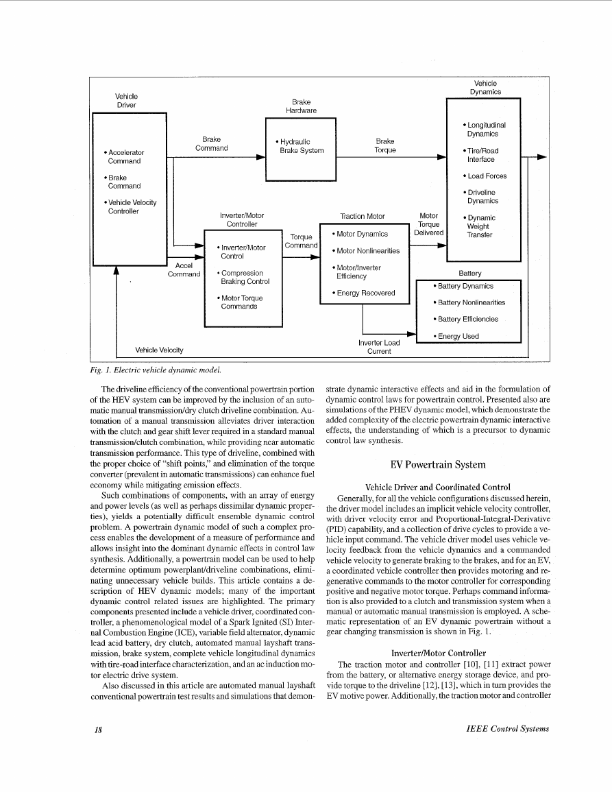
Fig. I . Electric vehicle dynamic model.
The driveline efficiency of the conventional powertrain portion
of the HEV system can be improved by the inclusion of an auto-
matic manual transmissioddry clutch driveline combination. Au-
tomation of a manual transmission alleviates driver interaction
with the clutch and gear shift lever required in a standard manual
bansmissiodclutch combination, while providing near automatic
transmission performance. This type of driveline, combined with
the proper choice of “shift points,” and elimination of the torque
converter (prevalent in automatic transmissions) can enhance fuel
economy while mitigating emission effects.
Such combinations of components, with an array of energy
and power levels (as well as perhaps dissimilar dynamic proper-
ties), yields a potentially difficult ensemble dynamic control
problem. A powertrain dynamic model of such a complex pro-
cess enables the development of a measure of performance and
allows insight into the dominant dynamic effects in control law
synthesis. Additionally, a powertrain model can be used to help
determine optimum powerplantldriveline combinations, elimi-
nating unnecessary vehicle builds. This article contains a de-
scription of HEV dynamic models; many of the important
dynamic control related issues are highlighted. The primary
components presented include a vehicle driver, coordinated con-
troller, a phenomenological model of a Spark Ignited (SI) Inter-
nal Combustion Engine (ICE), variable field altemator, dynamic
lead acid battery, dry clutch, automated manual layshaft trans-
mission, brake system, complete vehicle longitudinal dynamics
with tire-road interface characterization, and an ac induction mo-
tor electric drive system.
Also discussed in this article are automated manual layshaft
conventional powertrain test results and simulations that demon-
strate dynamic interactive effects and aid in the formulation of
dynamic control laws for powertrain control. Presented also are
simulations of the PHEV dynamic model, which demonstrate the
added complexity of the electric powertrain dynamic interactive
effects, the understanding of which is a precursor to dynamic
control law synthesis.
EV Powertrain System
Vehicle Driver and Coordinated Control
Generally, for all the vehicle configurations discussed herein,
the driver model includes an implicit vehicle velocity controller,
with driver velocity error and Propohonal-Integral-Denvatrve
(PID) capability, and a collection of drive cycles to provide a ve-
hicle input command. The vehicle driver model uses vehicle ve-
locity feedback from the vehicle dynamics and a commanded
vehicle velocity to generate braking to the brakes, and for an EV,
a coordinated vehicle controller then provides motoring and re-
generative commands to the motor controller for corresponding
positive and negative motor torque. Perhaps command informa-
tion is also provided to a clutch and transmission system when a
manual or automatic manual transmssion is employed. A sche-
matic representation of an EV dynamic powertrain without a
gear changing transmission is shown in Fig. 1.
Inverter/Motor Controller
The traction motor and controller [lo], [11] extract power
from the battery, or alternative energy storage device, and pro-
vide torque to the driveline [ 121, [ 131, which in turn provides the
EV motive power. Additionally, the traction motor and controller
18
IEEE Control Systems
Brake
Hardware
Brake
Command
Hydraulic
Brake System
Brake
Brake
Torque
Torque
Vehicle
Driver
Accelerator
Command
Brake
Command
Vehicle Velocity
Controller
1
-
I
4
I
Vehicle
Dynamics
Longitudinal
Longitudinal
Dynamics
Dynamics
Tire/Road
Tire/Road
Interface
Interface
Load Forces
Load Forces
Driveline
Dynamics
Dynamic
Weight
Transfer
Battery
Battery Dynamics
Battery Nonlinearities
Battery Efficiencies
�
may be operated as a starter/alternator combination [14] or as a
generator used to recover the vehicle kinetic energy dissipated
during braking [ 1.51, [ 161. The traction motor and controller then
provide power to the battery or altemative power source, and
negative torque to the driveline, which in turn brakes the vehicle.
The coordination of electric and hydraulic blending, during
braking, is performed by the traction motor controller to meet the
driver brake torque command. Compression braking torque,
electric braking torque used to emulate the feel of engine drag
present on an IC engine vehicle, is also determined by the trac-
tion motor controller. All negative motor torque is reduced lin-
early at low vehicle speeds where no energy can be recovered.
Clompression braking torque allows braking to occur while re-
covering the maximum energy, due to all braking being per-
folrmed electrically.
Traction Motor Dynamics
The traction motor dynamic model [lo] represents the dy-
namics of a specific field oriented controlled ac induction motor
as described by the following equations:
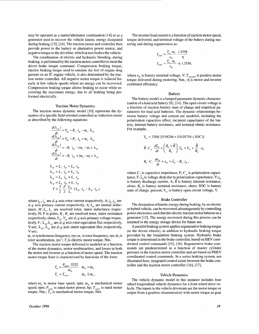
h,, = L, .iqs + L, .iqr
h,, = L,T .id + L, .id,
A,, =Lm.iqa +L;iq,
h, = L, . i, + L, ' i,
wlherei,,, iqr are d,q axis rotor current respectively, A; ids,iqs are
d , q axis primary current respectively, A; L, are mutual induc-
tance, H ; Lr, LJ are resolved rotor, stator inductance respec-
tively, H; P is poles; Rr, Rs are resolved rotor, stator resistance
reispectively, ohms; V,, Vqs are d, q axis primary voltage respec-
tively, V; h,,,h qr are d, q axis rotor equivalent flux respectively,
V-sec; h,, h , are d,q axis stator equivalent flux respectively,
V-sec;
o, is synchronous frequency, rps; or is rotor frequency, rps; &,is
rotor acceleration, rps*; T,is electric motor torque, Nm.
The traction motor torque delivered is modeled as a function
of the motor dynamics, motor nonlinearities, and losses in both
the motor and inverter as a function of motor speed. The traction
motor torque limit is characterized by functions of the form:
The inverter load current is a function of traction motor speed,
torque delivered, and terminal voltage of the battery during mo-
toring and during regeneration as:
where elb is battery terminal voltage, V; Tmposdel
is positive motor
torque delivered during motoring, Nm.; q is motor and inverter
combined efficiency.
Battery
The battery model is a lumped parameter dynamic character-
ization of a lead acid battery [8], [14]. The open circuit voltage is
a function of traction battery state of charge and empirical pa-
rameters for lead acid batteries. The dynamic relationships be-
tween battery voltage and current are modeled, including the
polarization capacitive effect, incipient capacitance of the bat-
tery, internal battery resistance, and terminal ohmic resistance.
For example,
V,, = 338.8.[0.94246 + 0.0.05754.( SOC)]
+ elb = zCh - R~ . ilh ,
R~ .
.
dt
where C, is capacitive impedance, F; C, is polarization capaci-
tance, F; Zlbis voltage drop due to_polarization capacitance, V; ilb
is battery discharge current, A; R is battery intemal resistance,
ohms; Rb is battery terminal resistance, ohms; SOC is battery
state of charge, percent; V,, is battery open circuit voltage, V.
Brake Controller
The dissipation of kinetic energy during braking, by an electric
or hybrid vehicle, can be recovered advantageously by controlling
power electronics such that the electric traction motor behaves as a
generator [ 121. The energy recovered during this process can be
returned to the energy storage device for future use.
A parallel braking system applies regenerative braking torque
(to the driven wheels), in addition to hydraulic braking torque
provided by the foundation braking system. Hydraulic brake
torque is determined in the brake controller, based on HEV coor-
dinated control commands [ 1.51, [ 161. Regenerative brake com-
mands are predetermined as a function of master cylinder
pressure in the traction motor controller and are based on PHEV
coordinated control commands. In a series braking system, not
illustrated here, integrated control exists between the brake con-
troller and the traction motor controller [16], [17].
T, = Tared
a,
box input. In addition, the vehicle drivetrain receives hydraulic
brakmg torque or other driveline loads, and vehicle velocity is
determined via integration of the longitudinal equations of mo-
tion. Rotational dynamics for each wheel, and halfshafts, and a
representation of the forces acting on the vehicle, are modeled.
Rotational wheel dynamics include wheel slip (skid), tireiroad
surface adhesion coefficient, wheel tractive force as a function of
dynamic weight transfer, road load torque for each wheel, and
rotational wheel speed.
Wheel slip (skid) is used to determine the tireiroad surface ad-
hesion coefficient with a nonlinear analytic tireiroad surface inter-
face model [l], [3], [17]. The tire model used for this study
assumed a high road surface adhesion coefficient for dry pave-
ment, because these are conventional driving conditions. The
wheel tractive force as a function of dynamic weight transfer is
the product of the road surface adhesion coefficient and the nor-
mal force acting on the wheel:
In calculating the normal forces acting on each wheel, the dy-
namic weight transfer is modeled for each of both front and rear
wheels in terms of the vehicle pitch and lever arms (wheel base)
to the vehicle center of mass. The road load torque for each wheel
is then determined from the wheel diameter and tractive force:
The torques acting on the wheels include the halfshaft torque, Ts,
road load torque, Tb, bearing friction torque, and the braking
torque. Rotational wheel acceleration is obtained by the sum of
the torque acting on the wheel divided by the wheel inertia.
Wheel speed is obtained by integrating rotational wheel acceler-
ation:
The halfshaft model accounts for the torsional compliance be-
tween the differential and wheel. The resulting halfshaft torque is
applied to the wheel. The relations for shaft torque, and shaft com-
pliance in terms of physical parameters are shown below:
The four wheel tractive forces, aerodynamic drag, grade
forces, and rolling resistance, describe the forces acting on the
vehicle and are depicted below:
Ft”, = Ft,, + Elr f Ft$ + Fdf - Fa,, - Fry - Fgrada .
The aerodynamic drag on the vehicle is a function of vehicle
velocity squared, air density, vehicle frontal area, and coefficient
of drag, where the vehicle velocity is determined by solving €or
vehicle acceleration and integrating over time:
The rolling resistance force is a function of vehicle weight, roll-
ing resistance coefficient, and vehicle speed:
F,, = f, . W, .1.3558(1+ k, . V + k, . V’)
The grade forces acting on the vehicle are a function of vehi-
cle weight and grade angle:
FgrOd, = W, .1.3558 sin0 .
plied by the vehicle acceleration.
The total forces on the vehicle equal the vehicle mass multi-
In these equations, 4 is frontal area of vehicle,m2;Cd is aero-
dynamic drag coefficient; Fa,, is aerodynamic drag force on ve-
hicle, N; Fgrad, is grade force on vehicle, N; Frr is rolling
resistance force on vehicle, N; f , is rolling resistance coefficient;
ev is tractive force on left front wheel, N; c,r is tractive force on
left rear wheel, N; e,, is total forces acting on vehicle, N; F,$ is
tractive force on right front wheel, N; Jdq is differential inertia,
kg.m2 ; Jfd-dg is final drive inertia on differential side, k g , m 2 ;
J , is wheel inertia, kg .m2 K , is halfshaft stiffness, “/rad; K , is
empirical constant; K2 is empirical constant; R,, is loss in shaft
bearings, k g . m 2 i sec.rad ; R, is wheel radius, ft; Tb is brake
torque, Nm; T
is final drive output torque, Nm; TIoad is road
torque, Nm; Tsis halfshaft torque, Nm; V is vehicle velocity,
fd.
m i sec2 ; W,is vehicle weight, lbf; y is air density, kg i m ; 8 is
grade angle, rad; 0, is halfshaft displacement, rad; p(7r,lr,rf,y)
is
coefficient of friction on right rear, left rear, right front, and left
front wheels respectively; 03 is wheel speed, radfsec; cofd is final
drive speed on differential side, radfsec; ol, is left wheel speed,
radisec; w, is right wheel speed, radisec.
Series HEV Powertrain System
Vehicle Driver and Coordinated Control
A Series HEV (SHEV) powertrain may be achieved with the
addition of an auxiliary power plant to the electric vehicle in
power series connection with the traction battery and traction
motor. In a “senes” configuration, the power unit interacts with
the vehicle system controller and the rest of the vehicle electrical
system, which includes the vehicle traction motor and other an-
cillary loads such as power steering or air conditioning. The ve-
hicle system controller provides a desired power command and a
desired engine speed command to the SHEV system. Two or
more control variables may be used to attempt to achieve the de-
sired altemator power at a desired engine speed. In addition, the
coordinated vehicle controller provides motoring and regenera-
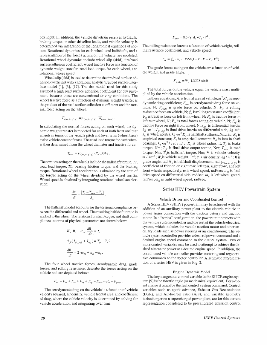
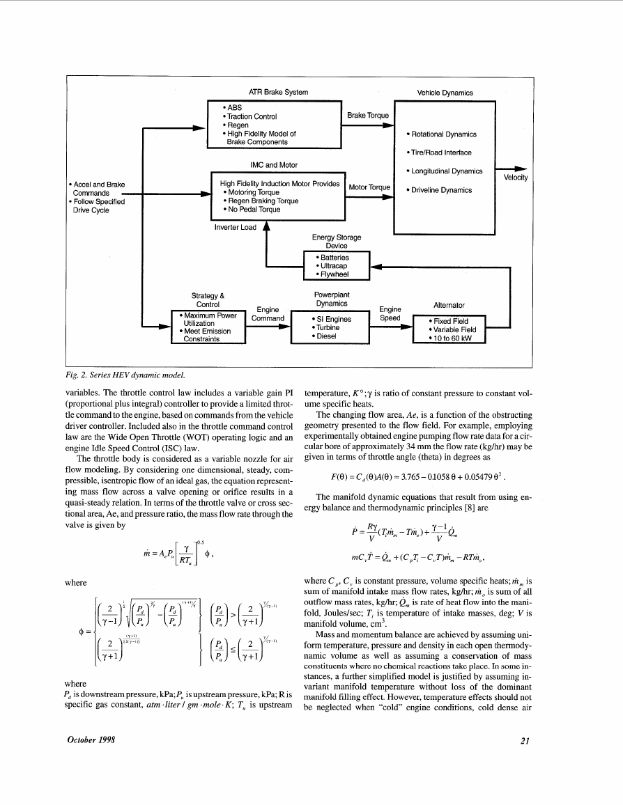
tive commands to the motor controller. A schmatic representa-
tion of a series HEV is given in Fig. 2.
Engine Dynamic Model
The key exogenous control variable to the SI ICE engine sys-
tem [9] is the throttle angle (or mechanical equivalent). For a die-
sel engine it might be the fuel control system command. Control
variables such as spark advance, Exhaust Gas Recirculation
(EGR), and Air-to-Fuel ratio (AF), and variable geometry
turbocharger on a supercharged power plant, are for this current
representation considered to be precalibrated emission control
20
IEEE Control Systems
�
ATR Brake System
Vehicle Dynamics
Brake Torque
I
Rotational Dynamics
*Tire/Road lntetface
Longitudinal Dynamics
Driveline Dynamics
ICommands -
Accel and Brake
Follow Specified
13rive Cycle
High Fidelity Model of
Brake Components
IMC and Motor
High Fidelity Induction Motor Provides
Motoring Torque
Regen Braking Torque
No Pedal Torque
t
Inverter Load
-
-
Strateav &
Maximum Power
Maximum Power
Utilization
Utilization
Meet Emission
Meet Emission
Constraints
Constraints
Command
Command
b
b
Energy Storage
Device
Batteries
Powerplant
SI Engines
SI Engines
Turbine
Turbine
Diesel
Diesel
Speed
Speed
I
*Variable Field -
Fixed Field
Fixed Field
Variable Field
10 to 60 kW
10 to 60 kW
temperature, KO; y is ratio of constant pressure to constant vol-
ume specific heats.
The changing flow area, Ae, is a function of the obstructing
geometry presented to the flow field. For example, employing
experimentally obtained engine pumping flow rate data for a cir-
cular bore of approximately 34 mm the flow rate (kghr) may be
given in terms of throttle angle (theta) in degrees as
F ( e ) = c,(e)A(e) = 3.765 - 0.1058 e + 0.05479 e* .
The manifold dynamic equations that result from using en-
ergy balance and thermodynamic principles [8] are
P . = -(Th,,,
RY
V
-Tho)+ -Qm y-1 ‘
V
where C,, C , is constant pressure, volume specific heats; m,,, is
sum of manifold intake mass flow rates, kghr; riz, is sum of all
outflow mass rates, kghr; Q, is rate of heat flow into the mani-
fold, Jouleslsec; Tt is temperature of intake masses, deg; V is
manifold volume, cm3.
Mass and momentum balance are achieved by assuming uni-
form temperature, pressure and density in each open thermody-
namic volume as well as assuming a conservation of mass
constituents where no chemical reactions take place. In some in-
stances, a further simplified model is justified by assuming in-
variant manifold temperature without loss of the dominant
manifold filling effect. However, temperature effects should not
be neglected when “cold” engine conditions, cold dense air
Fig. 2. Series HEV dynamic model.
variables. The throttle control law includes a variable gain PI
(proportional plus integral) controller to provide a limited throt-
tle command to the engine, based on commands from the vehicle
driver controller. Included also in the throttle command control
law are the Wide Open Throttle (WOT) operating logic and an
engine Idle Speed Control (ISC) law.
The throttle body is considered as a variable nozzle for air
flow modeling. By considering one dimensional, steady, com-
pressible, isentropic flow of an ideal gas, the equation represent-
ing mass flow across a valve opening or orifice results in a
quasi-steady relation. In terms of the throttle valve or cross sec-
tional area, Ae, and pressure ratio, the mass flow rate through the
valve is given by
where
where
P, is downstream pressure, kPa; P, is upstream pressure, kPa; R is
specific gas constant, atm .liter I gm .mole. K ; Tu is upstream
October 1998
21
�
charge, or evaporating and condensing fuel are important dy-
namic issues.
An estimation of mass flow rates out of the manifold is given
approximately by a product of the engine speed, engine displace-
ment, and volumetric efficiency, which in turn is resolved in
terms of engine speed, intake temperature, manifold pressure,
and exhaust gas pressure. Manifold mass flow rate egress is
given in terms of manifold pressure and engine speed by an ap-
proximate polynomial functional form
.
M = ---(OS22
N
1000
+ O.OS553(-))(0.17P+
N
1000
0.00098P2),
where M is speed density mass flow rate, kg/hr and N is engine
speed, rpm.
The engine torque developed at any time is a function of the
mass rates (mass charge) or ratios of rates (mass constituents)
that were sampled one engine induction event earlier. This
breathing event is a crank angle synchronized relationship that is
primarily dependent 011 engine speed. For a zero order extrapola-
tion, the minimum delay in torque generation that results from
ingestion of the manifold constituents is 180 crankangle degrees.
For a four cylinder engine with a speed of N RPM, this is repre-
sented by a propagation lag relationship with idealized delay T is
30/N seconds.
A similar lag exists for the mixed A/F from the end of com-
bustion to exhaust valve closure. In addition, a nonspeed depend-
ent propagation lag, and some gaseous diffusion, is assumed to
persist in the exhaust pipe before the A/F sensor location [18].
Representation of the A/F delays in an SI ICE is extremely im-
portant as the torque response is highly sensitive to A/F tran-
sients, including throttle input and fuel control system transients.
The nonlinear structure for the A/F (Air/Fuel) system con-
sists of an EGO (exhaust gas oxygen) A/F sensor in the exhaust
pipe, with a time constant of the order of 70 ms, followed by a
nonlinear (Nernst) rich/lean Signum function and a PI fuel com-
mand control law [18]. An intake runner port fuel injector is as-
sumed with a fuel rate output, and with fuel condensation and
evaporation dynamics [ 191. The resulting system equations are
.
dm
T -‘=rp~~-m~,
” dt m, = (1 - Tl)rifi + mi,
,
m is manifold fuel flow rate, kglhr; m t~ is injector fuel rate com-
mand, kg/hr;nifL is injected fuel flow rate, kglhr;m is fuel evapo-
ration rate, kghr; q is fuel accumulation parameter, = 0.25 sec; T~
is injector time constant, = 50 ms; 7, is condensation and evapo-
ration time, = 0.5 sec.
The fuel mass flow rate is combined with the throttle mass air
flow rate to form the manifold A/F. This A/F is delayed by the in-
duction breathing lag, preparatory to combustion torque genera-
tion, followed by a combustion torque delay, a power-stroke to
exhaust delay, and a plug stroke exhaust system delay that is de-
pendent on the location of the EGO sensor.
Torque generated from the combustion process is dependent
on the ignition of a cylinder charge o f air, fuel, and residual gas,
as well as other variables and parameters that influence combus-
tion efficiency. Assuming a spark advance, EGR (exhaust gas
recirculation), and fuel emission calibrated 1.8 liter engine, an
approximate brake torque relationship is of the form
T = q ( A l F , ( A / F ) 2 , M , M 2 , N ,..., N4, EGR).
The rotational motion of the engine crankshaft is given in
terms of the engine polar moment of inertia, angular accelera-
tion, and the difference between the net torque generated by the
engine and the load torque on the driveshaft. Thus,
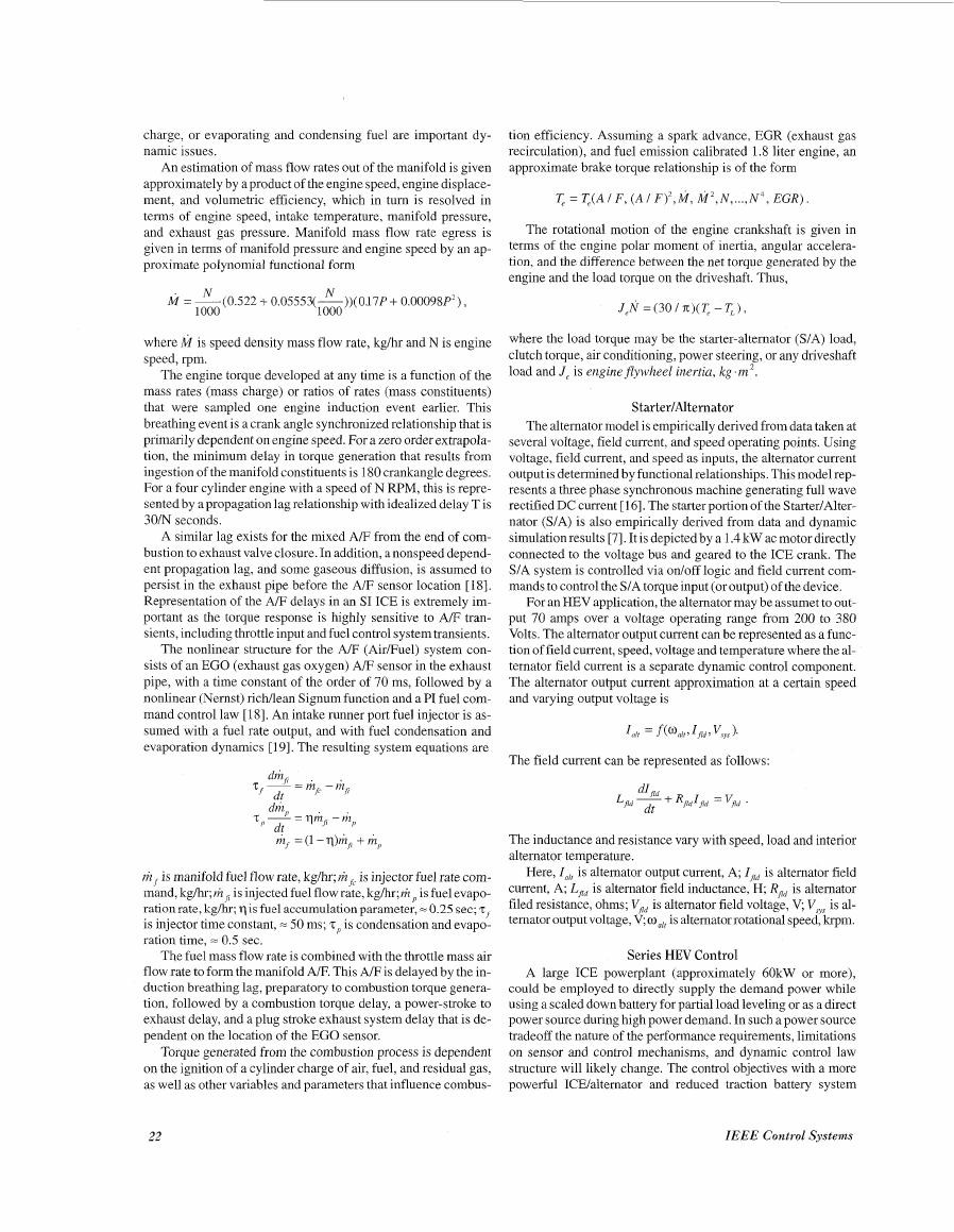
J,N = (30 / E)( T, -
where the load torque may be the starter-alternator (S/A) load,
clutch torque, air conditioning, power steering, or any driveshaft
load and J , is engine flywheel inertia, kg . m ’.
StartedAlternator
The alternator model is empirically derived from data taken at
several voltage, field current, and speed operating points. Using
voltage, field current, and speed as inputs, the alternator current
output is determined by functional relationships. This model rep-
resents a three phase synchronous machine generating full wave
rectified DC current [ 161. The starter portion of the StartedAlter-
nator (S/A) is also empirically derived from data and dynamic
simulation results [7]. It is depicted by a 1.4 kW ac motor directly
connected to the voltage bus and geared to the ICE crank. The
S/A system is controlled via on/off logic and field current com-
mands to control the S/A torque input (or output) of the device.
For an HEV application, the alternator may be assumet to out-
put 70 amps over a voltage operating range from 200 to 380
Volts. The alternator output current can be represented as a func-
tion of field current, speed, voltage and temperature where the al-
ternator field current is a separate dynamic control component.
The alternator output current approximation at a certain speed
and varying output voltage is
The field current can be represented as follows:
The inductance and resistance vary with speed, load and interior
alternator temperature.
Here, I,,l is alternator output current, A; I , is alternator field
current, A; Lfld is alternator field inductance, H; R, is alternator
is alternator field voltage, V; V,,, is al-
filed resistance, ohms; V,,
ternator output voltage, V mail is alternator rotational speed, krpm.
Series HEV Control
A large ICE powerplant (approximately 60kW or more),
could be employed to directly supply the demand power while
using a scaled down battery for partial load leveling or as a direct
power source during high power demand. In such a power source
tradeoff the nature of the performance requirements, limitations
on sensor and control mechanisms, and dynamic control law
structure will likely change. The control objectives with a more
powerful ICE/alternator and reduced traction battery system
22
IEEE Control Systems
�
340
338
336
334
332
330
328
326
324
1000 \
500 1
0
0
1
I
I
15
5
10
Fig. 3. Series power unit control.
might yield a load leveling or load following strategy [20]. In this
instance, the combined powerplanthattery system would be the
prime vehicle power source used to follow the desired vehicle pro-
file while the battery power supply would be used to mitigate the
traction motor transient demands to the ICE/altemator system.
Simulation results for such a combination are shown in Fig. 3.
In this simulation, the vehicle driver would like to follow the
the first few active (non-idle) seconds of the Federal Urban
Driving Cycle (FUDS). In the transient behavior depicted in
Fig. 3, the driver’s input goes directly to the Induction Motor
Control (IMC) of the traction motor and simultaneously to the
thirottle command of the ICE. Until the ICE/alternator can
achieve alternator “cut-in’’ (i.e., that speed at which there is a
power output from the alternator), the traction motor draws
power from the energy storage device which in this case is a low
storage (small) battery pack. The combination of components
thus illustrated would require a smaller battery pack and re-
duced ICE by proper sizing and proration of power between the
ICE and energy storage device.
Simulations that include engine, alternator, battery, and trac-
tion motor/driveline sizing and dynamic interactions, could be
used to examine energy tradeoffs and transient tradeoffs by vary-
ing control and sizing (kW output) between an alternator and bat-
tery system as series power sources. For instance, for a small
ICE-alternator-battery power source (about 25 kW), a system
operating strategy could be such that the “Range Extender” (RE)
is to be activated during estimated low battery State-of-Charge
(SOC) and simply operates until a desired SOC [8], [20] has been
achieved. There exists dynamic interaction among the ICE, alter-
nator, battery and vehicle traction motor (drivetrain) such that en-
Olctober 1998
23
�
ified operating strategy.
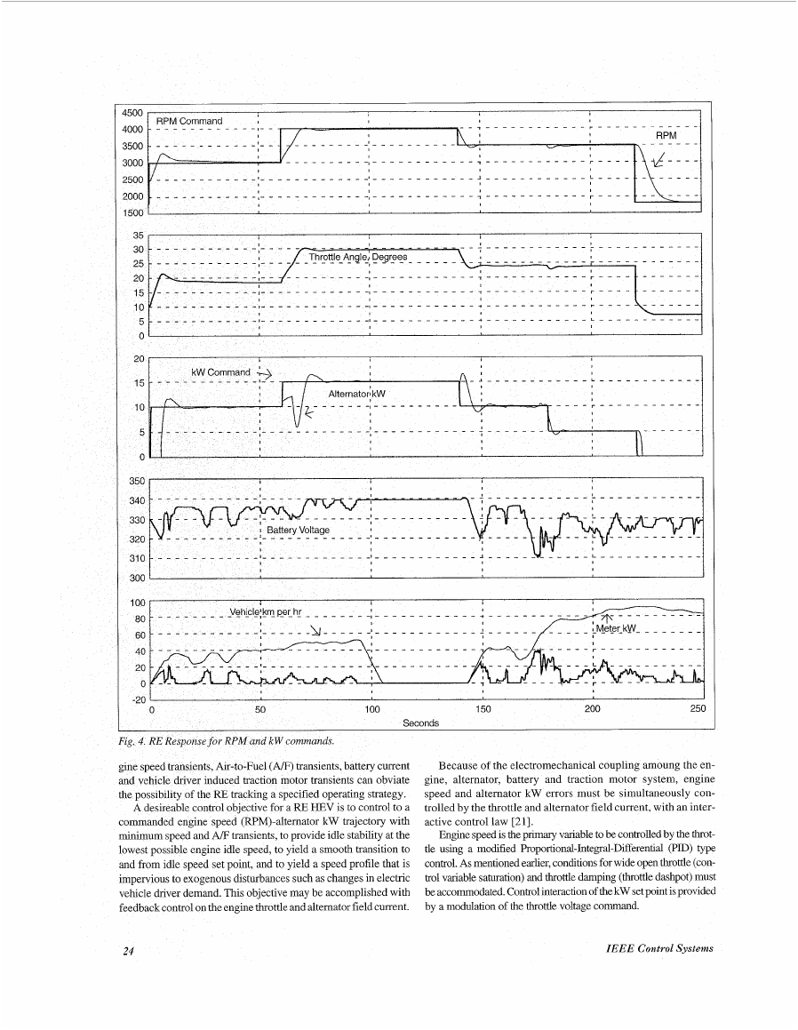
A desireable control objective for a RE HEV is to control to a
commanded engine speed (RPM)-alternator kW trajectory with
minimum speed and A/F transients, to provide idle stability at the
lowest possible engine idle speed, to yield a smooth transition to
and from idle speed set point, and to yield a speed profile that is
impervious to exogenous disturbances such as changes in electric
vehicle driver demand. This objective may be accomplished with
feedback control on the engine throttle and alternator field current.
speed and alternator kW errors must be simultaneously con-
trolled by the throttle and alternator field current, with an inter-
active control law [21].
Engine speed is the pnmaq variable to be controlled by the throt-
tle using a modified Proportional-Integral-Differentd (PID) type
control. As mentioned earlier, conditions for wide open throttle (con-
trol variable saturation) and throttle damping (throttle dashpot) must
be accommodated. Control interaction of the kW set point is provided
by a modulation of the throttle voltage command.
24
IEEE Control Systems
�



 2023年江西萍乡中考道德与法治真题及答案.doc
 2012年重庆南川中考生物真题及答案.doc
 2013年江西师范大学地理学综合及文艺理论基础考研真题.doc
 2020年四川甘孜小升初语文真题及答案I卷.doc
 2020年注册岩土工程师专业基础考试真题及答案.doc
 2023-2024学年福建省厦门市九年级上学期数学月考试题及答案.doc
 2021-2022学年辽宁省沈阳市大东区九年级上学期语文期末试题及答案.doc
 2022-2023学年北京东城区初三第一学期物理期末试卷及答案.doc
 2018上半年江西教师资格初中地理学科知识与教学能力真题及答案.doc
 2012年河北国家公务员申论考试真题及答案-省级.doc
 2020-2021学年江苏省扬州市江都区邵樊片九年级上学期数学第一次质量检测试题及答案.doc
 2022下半年黑龙江教师资格证中学综合素质真题及答案.doc