机构运动学仿真
仿真内容:滑块加速度 1r 、滑块速度 1r 、滑块位移 1r 、曲柄角速度 2 、曲柄转角 2 、
连杆角加速度 3 、连杆角速度 2 和连杆角位移 2 。下面简要陈述仿真过程。
(1) 已知的机构运动学参数
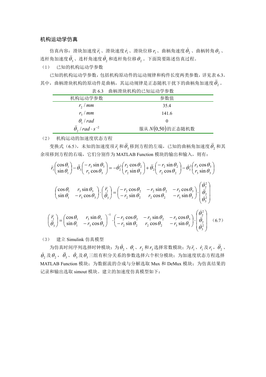
已知的机构运动学参数,包括机构原动件的运动规律和构件长度两类参数,详见表 6.3。
其中,曲柄滑块机构的原动件是曲柄,其运动规律是正态随机干扰下的曲柄角加速度 2 。
表 6.3 曲柄滑块机构的已知运动学参数
参数值
35.4
141.6
2
0
50,0N
的正态随机数
服从
机构运动学参数
r /2
mm
r /3
mm
/1
rad
rad
2 /
s
(2) 机构运动的加速度状态方程
变换式(6.5),未知的加速度项 1r 和 3 移到方程的左端,已知的曲柄角加速度 2 和其
余项移到方程的右端,它们分别作为 MATLAB Function 模块的输出和输入,则有:
r
1
cos
sin
1
3
1
sin
r
3
3
cos
r
3
3
2
2
r
2
r
2
cos
sin
2
2
2
sin
r
2
2
2
cos
r
3
2
2
r
3
r
3
cos
sin
3
3
cos
sin
1
1
r
sin
r
1
3
3
cos
r
3
3
3
r
2
r
2
cos
sin
2
2
sin
r
2
2
cos
r
2
2
r
3
r
3
cos
sin
3
3
2
2
2
2
3
r
1
3
cos
sin
1
1
1
sin
r
3
3
cos
r
3
3
r
2
r
2
cos
sin
2
2
sin
r
2
2
cos
r
2
2
r
3
r
3
cos
sin
3
3
2
2
2
2
3
(6.7)
(3) 建立 Simulink 仿真模型
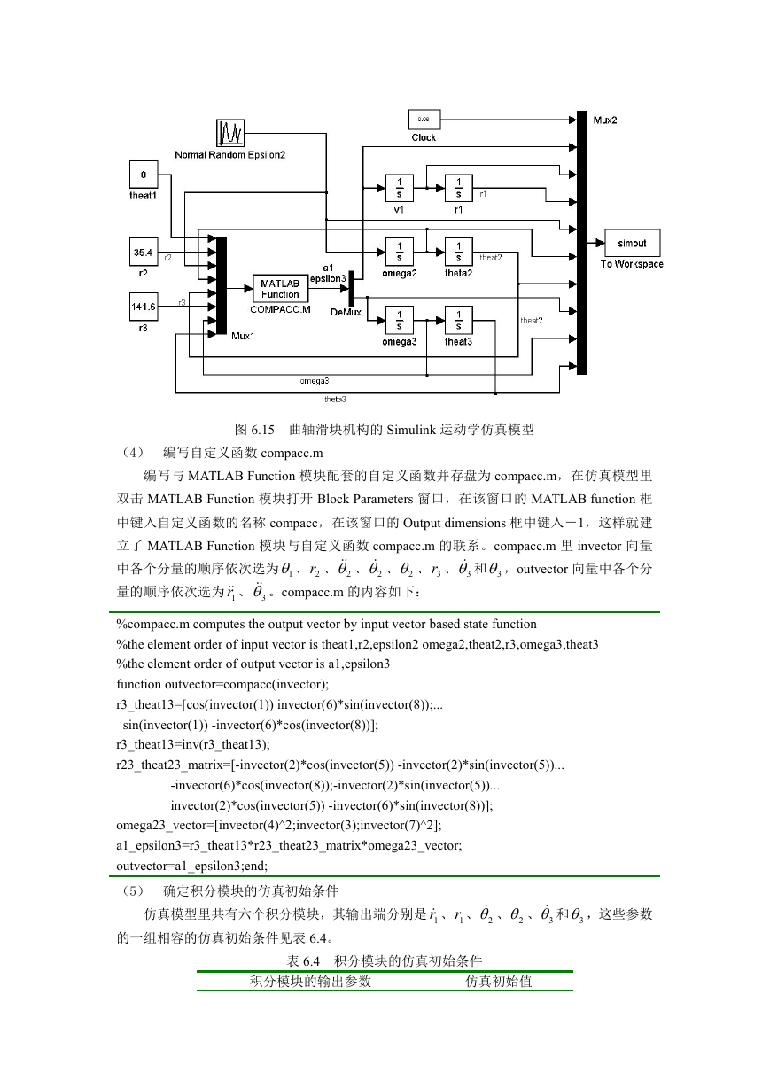
为仿真时间序列选择时钟模块;为 2 、 1 、 2r 和 3r 选择常数模块;为 1r 、 1r 及 1r , 2 、
2 及 2 , 3 、 3 及 3 三组有积分关系的参数选择六个积分模块;为加速度状态方程选择
MATLAB Function 模块;为数据流的合成与分解选取 Mux 和 DeMux 模块;为仿真结果的
记录和输出选取 simout 模块。建立的加速度仿真模型如下:
�
图 6.15 曲轴滑块机构的 Simulink 运动学仿真模型
(4) 编写自定义函数 compacc.m
编写与 MATLAB Function 模块配套的自定义函数并存盘为 compacc.m,在仿真模型里
双击 MATLAB Function 模块打开 Block Parameters 窗口,在该窗口的 MATLAB function 框
中键入自定义函数的名称 compacc,在该窗口的 Output dimensions 框中键入-1,这样就建
立了 MATLAB Function 模块与自定义函数 compacc.m 的联系。compacc.m 里 invector 向量
中各个分量的顺序依次选为 1 、 2r 、 2 、 2 、 2 、 3r 、 3 和 3 ,outvector 向量中各个分
量的顺序依次选为 1r 、 3 。compacc.m 的内容如下:
%compacc.m computes the output vector by input vector based state function
%the element order of input vector is theat1,r2,epsilon2 omega2,theat2,r3,omega3,theat3
%the element order of output vector is a1,epsilon3
function outvector=compacc(invector);
r3_theat13=[cos(invector(1)) invector(6)*sin(invector(8));...
sin(invector(1)) -invector(6)*cos(invector(8))];
r3_theat13=inv(r3_theat13);
r23_theat23_matrix=[-invector(2)*cos(invector(5)) -invector(2)*sin(invector(5))...
-invector(6)*cos(invector(8));-invector(2)*sin(invector(5))...
invector(2)*cos(invector(5)) -invector(6)*sin(invector(8))];
omega23_vector=[invector(4)^2;invector(3);invector(7)^2];
a1_epsilon3=r3_theat13*r23_theat23_matrix*omega23_vector;
outvector=a1_epsilon3;end;
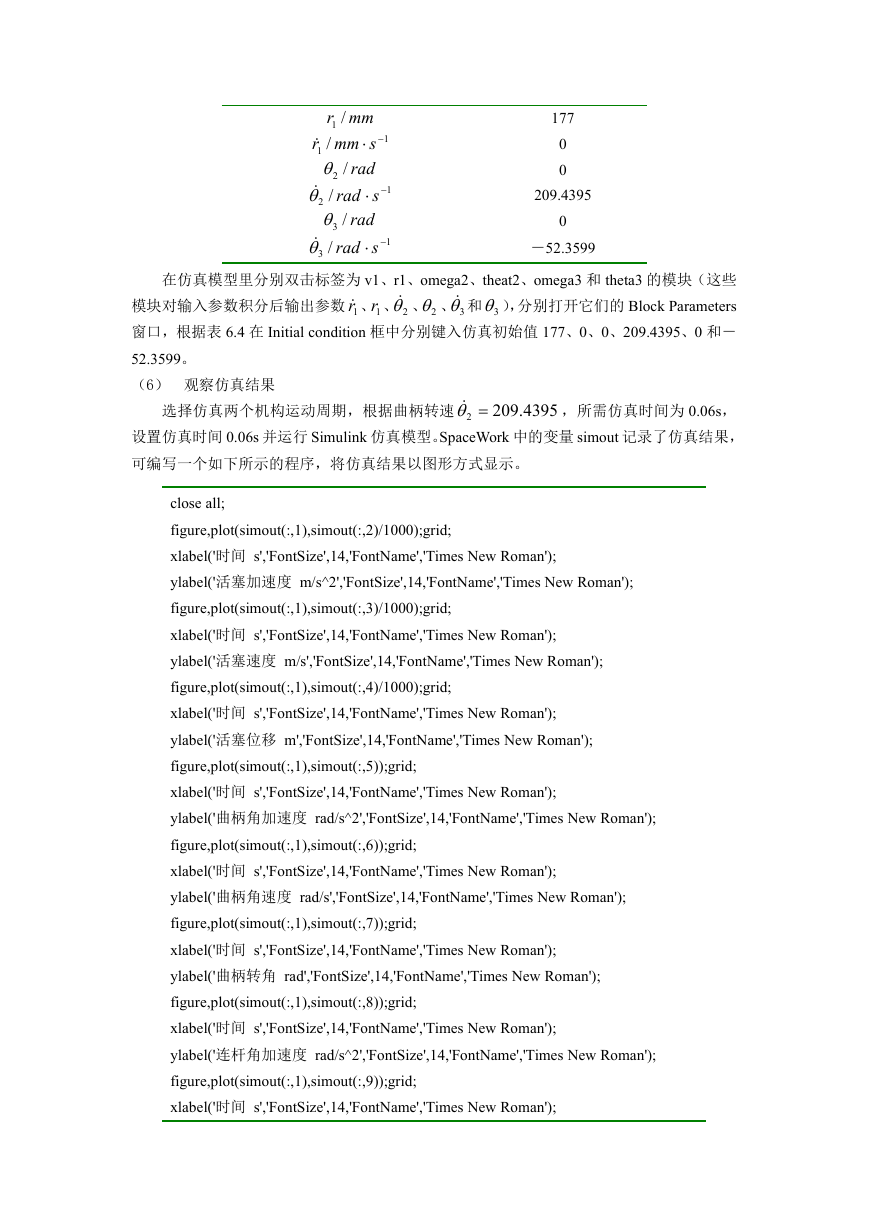
(5) 确定积分模块的仿真初始条件
仿真模型里共有六个积分模块,其输出端分别是 1r 、 1r 、 2 、 2 、 3 和 3 ,这些参数
的一组相容的仿真初始条件见表 6.4。
表 6.4 积分模块的仿真初始条件
积分模块的输出参数
仿真初始值
�
r /1
mm
1 /
smm
r
/2
rad
rad
2 /
s
/3
rad
rad
3 /
s
1
1
1
177
0
0
209.4395
0
-52.3599
在仿真模型里分别双击标签为 v1、r1、omega2、theat2、omega3 和 theta3 的模块(这些
模块对输入参数积分后输出参数 1r 、1r 、 2 、 2 、 3 和 3 ),分别打开它们的 Block Parameters
窗口,根据表 6.4 在 Initial condition 框中分别键入仿真初始值 177、0、0、209.4395、0 和-
52.3599。
(6) 观察仿真结果
选择仿真两个机构运动周期,根据曲柄转速
,所需仿真时间为 0.06s,
设置仿真时间 0.06s 并运行 Simulink 仿真模型。SpaceWork 中的变量 simout 记录了仿真结果,
可编写一个如下所示的程序,将仿真结果以图形方式显示。
209
.
4395
2
close all;
figure,plot(simout(:,1),simout(:,2)/1000);grid;
xlabel('时间 s','FontSize',14,'FontName','Times New Roman');
ylabel('活塞加速度 m/s^2','FontSize',14,'FontName','Times New Roman');
figure,plot(simout(:,1),simout(:,3)/1000);grid;
xlabel('时间 s','FontSize',14,'FontName','Times New Roman');
ylabel('活塞速度 m/s','FontSize',14,'FontName','Times New Roman');
figure,plot(simout(:,1),simout(:,4)/1000);grid;
xlabel('时间 s','FontSize',14,'FontName','Times New Roman');
ylabel('活塞位移 m','FontSize',14,'FontName','Times New Roman');
figure,plot(simout(:,1),simout(:,5));grid;
xlabel('时间 s','FontSize',14,'FontName','Times New Roman');
ylabel('曲柄角加速度 rad/s^2','FontSize',14,'FontName','Times New Roman');
figure,plot(simout(:,1),simout(:,6));grid;
xlabel('时间 s','FontSize',14,'FontName','Times New Roman');
ylabel('曲柄角速度 rad/s','FontSize',14,'FontName','Times New Roman');
figure,plot(simout(:,1),simout(:,7));grid;
xlabel('时间 s','FontSize',14,'FontName','Times New Roman');
ylabel('曲柄转角 rad','FontSize',14,'FontName','Times New Roman');
figure,plot(simout(:,1),simout(:,8));grid;
xlabel('时间 s','FontSize',14,'FontName','Times New Roman');
ylabel('连杆角加速度 rad/s^2','FontSize',14,'FontName','Times New Roman');
figure,plot(simout(:,1),simout(:,9));grid;
xlabel('时间 s','FontSize',14,'FontName','Times New Roman');
�
ylabel('连杆角速度 rad/s','FontSize',14,'FontName','Times New Roman');
figure,plot(simout(:,1),simout(:,10));grid;
xlabel('时间 s','FontSize',14,'FontName','Times New Roman');
ylabel('连杆角位移 rad','FontSize',14,'FontName','Times New Roman');
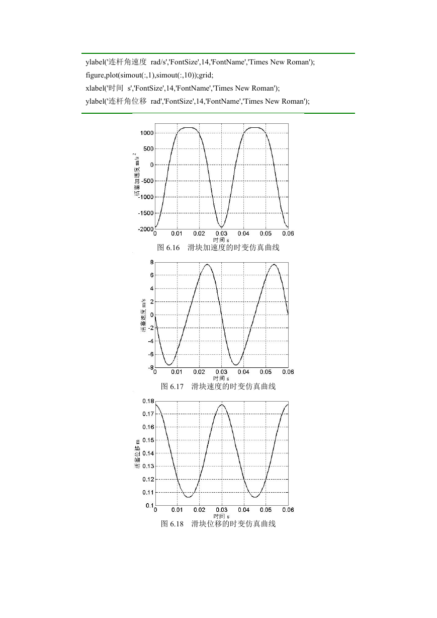
图 6.16 滑块加速度的时变仿真曲线
图 6.17 滑块速度的时变仿真曲线
图 6.18 滑块位移的时变仿真曲线
�
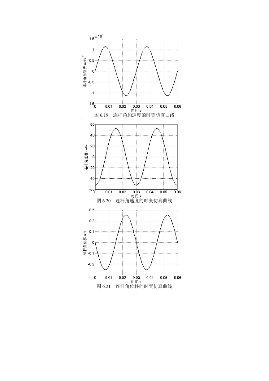
图 6.19 连杆角加速度的时变仿真曲线
图 6.20 连杆角速度的时变仿真曲线
图 6.21 连杆角位移的时变仿真曲线
�
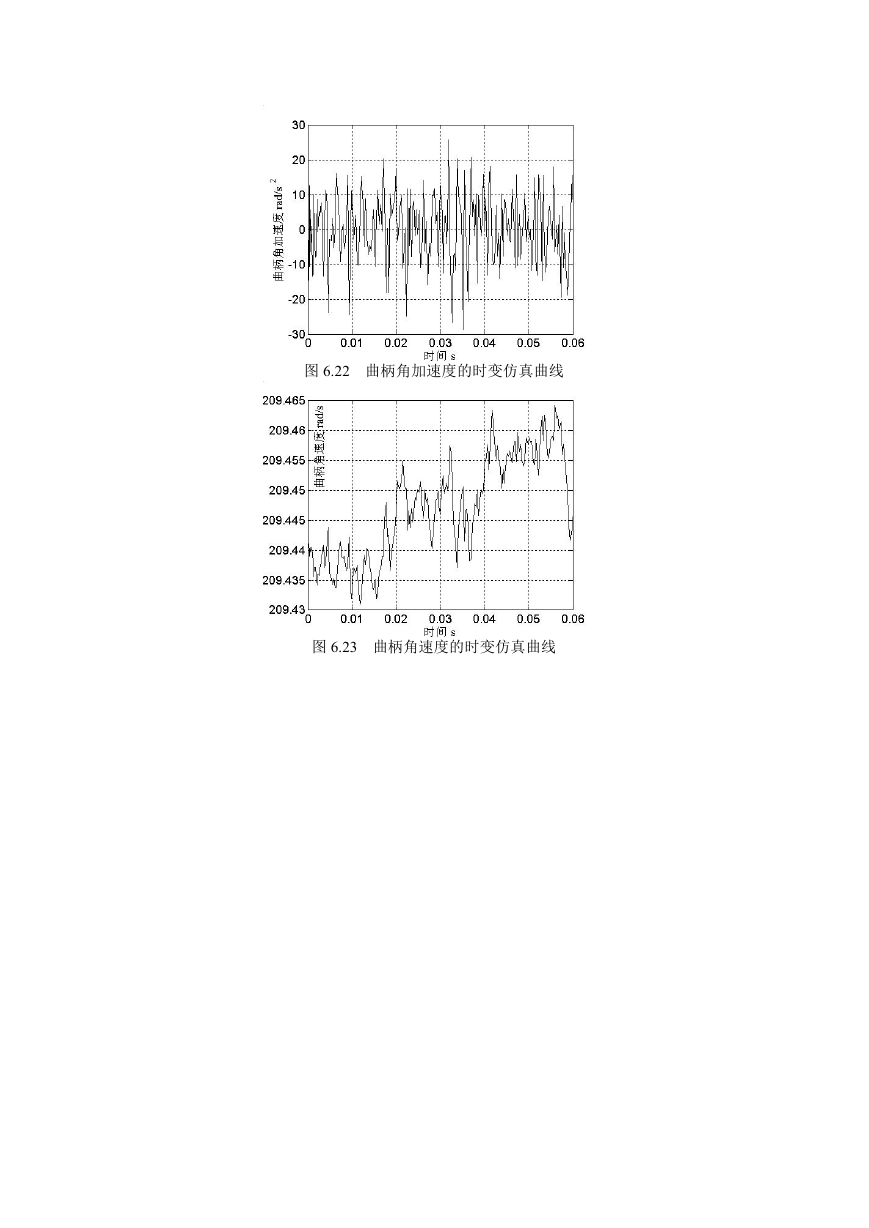
图 6.22 曲柄角加速度的时变仿真曲线
图 6.23 曲柄角速度的时变仿真曲线
�


 2023年江西萍乡中考道德与法治真题及答案.doc
 2012年重庆南川中考生物真题及答案.doc
 2013年江西师范大学地理学综合及文艺理论基础考研真题.doc
 2020年四川甘孜小升初语文真题及答案I卷.doc
 2020年注册岩土工程师专业基础考试真题及答案.doc
 2023-2024学年福建省厦门市九年级上学期数学月考试题及答案.doc
 2021-2022学年辽宁省沈阳市大东区九年级上学期语文期末试题及答案.doc
 2022-2023学年北京东城区初三第一学期物理期末试卷及答案.doc
 2018上半年江西教师资格初中地理学科知识与教学能力真题及答案.doc
 2012年河北国家公务员申论考试真题及答案-省级.doc
 2020-2021学年江苏省扬州市江都区邵樊片九年级上学期数学第一次质量检测试题及答案.doc
 2022下半年黑龙江教师资格证中学综合素质真题及答案.doc