1 Introduction
1.1 Objective
1.2 COM.0 R3.0 Changes from R2.1
Type 6
Type 10
Type 7
1.3 Name and Logo Usage
1.4 Intellectual Property
1.4.1 Necessary Claims (referring to mandatory or recommended features)
1.4.2 Unnecessary Claims (referring to optional features or non-normative elements)
1.4.3 Third Party Disclosures
1.5 Copyright Notice
1.5.1 Trademarks
1.6 Acronyms / Definitions
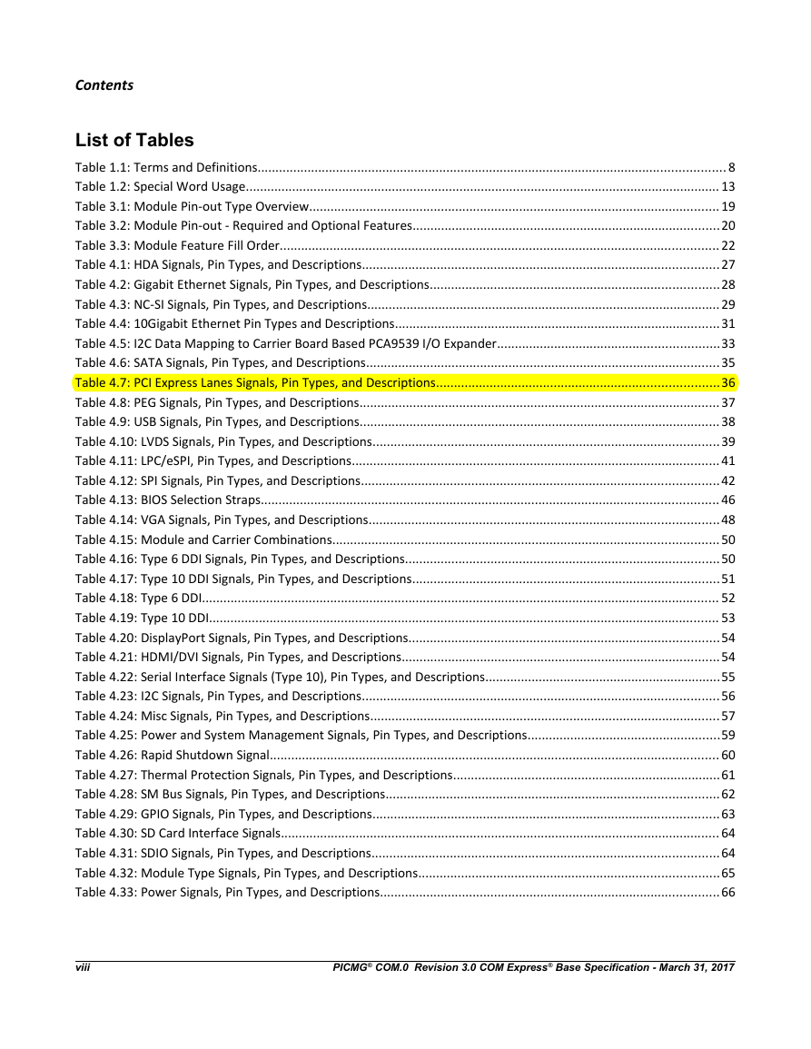
Table 1.1: Terms and Definitions
1.7 Applicable Documents and Standards
1.8 Special Word Usage
Table 1.2: Special Word Usage
1.9 Statement of Compliance
2 Module Overview
2.1 Module Configuration
2.2 Feature Overview - Size
2.2.1 Mini Module
2.2.2 Compact Module
2.2.3 Basic Module
2.2.4 Extended Module
2.3 Feature Overview - Pin-Out Types
2.3.1 Pin-Out Type 10
2.3.2 Pin-Out Type 6
2.3.3 Pin-Out Type 7
3 Required and Optional Features
3.1 Module Pin-Out Type Definitions
Table 3.1: Module Pin-out Type Overview
3.2 Module Pin-Out Types 6-7 & 10 - Required and Optional Features
Table 3.2: Module Pin-out - Required and Optional Features
3.3 Feature Fill Order
Table 3.3: Module Feature Fill Order
3.4 EAPI - Embedded Application Programming Interface
4 Signal Descriptions
4.1 Signal Naming Convention
4.2 Pin and Signal Buffer Types
4.2.1 Pin Types
4.2.2 Buffer Types
4.2.3 Power Rails and Tolerances
4.3 Signal List
4.3.1 High Definition Audio
Table 4.1: HDA Signals, Pin Types, and Descriptions
4.3.2 Gb Ethernet
Table 4.2: Gigabit Ethernet Signals, Pin Types, and Descriptions
4.3.3 NC-SI
Table 4.3: NC-SI Signals, Pin Types, and Descriptions
4.3.4 10Gb Ethernet
Table 4.4: 10Gigabit Ethernet Pin Types and Descriptions
AC Coupling of 10G_KR_TX Signals
Table 4.5: I2C Data Mapping to Carrier Board Based PCA9539 I/O Expander
4.3.5 SDP Pins
Pulse Per Second (PPS):
Platform-Level Synchronization Implementation Examples:
Precision Time Protocol - Background
Software Implementation:
4.3.6 Serial ATA
Table 4.6: SATA Signals, Pin Types, and Descriptions
4.3.7 General Purpose PCI Express Lanes
Table 4.7: PCI Express Lanes Signals, Pin Types, and Descriptions
4.3.8 PEG PCI Express Lanes
Table 4.8: PEG Signals, Pin Types, and Descriptions
4.3.9 USB
Table 4.9: USB Signals, Pin Types, and Descriptions
4.3.10 LVDS Flat Panel
Table 4.10: LVDS Signals, Pin Types, and Descriptions
4.3.11 LPC and eSPI Interface
Table 4.11: LPC/eSPI, Pin Types, and Descriptions
4.3.12 SPI Interface
Table 4.12: SPI Signals, Pin Types, and Descriptions
SPI Power
Module Vs Carrier Board Pull-ups
4.3.13 BIOS Boot Selection
Historical Context
SPI Boot Flash Background
MAFS and SAFS BIOS Configurations
Table 4.13: BIOS Selection Straps
SPI BIOS MAFS Considerations – LPC Enabled
SPI BIOS MAFS Considerations – eSPI Enabled
eSPI BIOS SAFS Considerations – eSPI Enabled
4.3.14 Analog VGA
Table 4.14: VGA Signals, Pin Types, and Descriptions
4.3.15 Digital Display Interfaces (DDI) - Module Type 6 and 10
Figure 4-6: Dual-Mode COM Express Module Implementation
Table 4.15: Module and Carrier Combinations
Requirements
Table 4.16: Type 6 DDI Signals, Pin Types, and Descriptions
Table 4.17: Type 10 DDI Signals, Pin Types, and Descriptions
Table 4.18: Type 6 DDI
Table 4.19: Type 10 DDI
4.3.16 DDI Signals: DisplayPort
Table 4.20: DisplayPort Signals, Pin Types, and Descriptions
4.3.17 DDI Signals: HDMI / DVI
Table 4.21: HDMI/DVI Signals, Pin Types, and Descriptions
4.3.18 General Purpose Serial Interface
Table 4.22: Serial Interface Signals (Type 10), Pin Types, and Descriptions
4.3.19 I2C Bus
Table 4.23: I2C Signals, Pin Types, and Descriptions
4.3.20 Miscellaneous
Table 4.24: Misc Signals, Pin Types, and Descriptions
4.3.21 Power and System Management
Table 4.25: Power and System Management Signals, Pin Types, and Descriptions
4.3.22 Rapid Shutdown
Table 4.26: Rapid Shutdown Signal
4.3.23 Thermal Protection
Table 4.27: Thermal Protection Signals, Pin Types, and Descriptions
4.3.24 SM Bus
Table 4.28: SM Bus Signals, Pin Types, and Descriptions
4.3.25 General Purpose Input Output
Table 4.29: GPIO Signals, Pin Types, and Descriptions
4.3.26 SDIO
Table 4.30: SD Card Interface Signals
Table 4.31: SDIO Signals, Pin Types, and Descriptions
4.3.27 Module Type Definition
Table 4.32: Module Type Signals, Pin Types, and Descriptions
4.3.28 Power and Ground
Table 4.33: Power Signals, Pin Types, and Descriptions
4.3.29 eDP - Embedded DisplayPort
Table 4.34: Module and Carrier Combinations Type 6 and Type 10 Modules
Table 4.35: eDP Signals
Table 4.36: LVDS / eDP Pin Assignment
4.3.30 CAN Bus
Table 4.37: CAN Bus Signals
4.4 Signals Requiring Carrier Board Termination
4.4.1 Ethernet
4.4.2 Analog VGA
4.4.3 LVDS
4.4.4 USB
4.4.5 Digital Display Interfaces (DDI)
4.4.6 VCC_RTC
4.4.7 EMI and ESD Mitigation
4.5 Signals Requiring Module Termination
4.5.1 AC coupled on the Module
4.5.2 Misc
4.6 Pin-out Tables
4.6.1 Type 10
Table 4.38: Pin List for Pin-Out Type 10
4.6.2 Type 6
Table 4.39: Pin List for Pin-Out Type 6
4.6.3 Type 7
Table 4.40: Pin List for Pin-Out Type 7
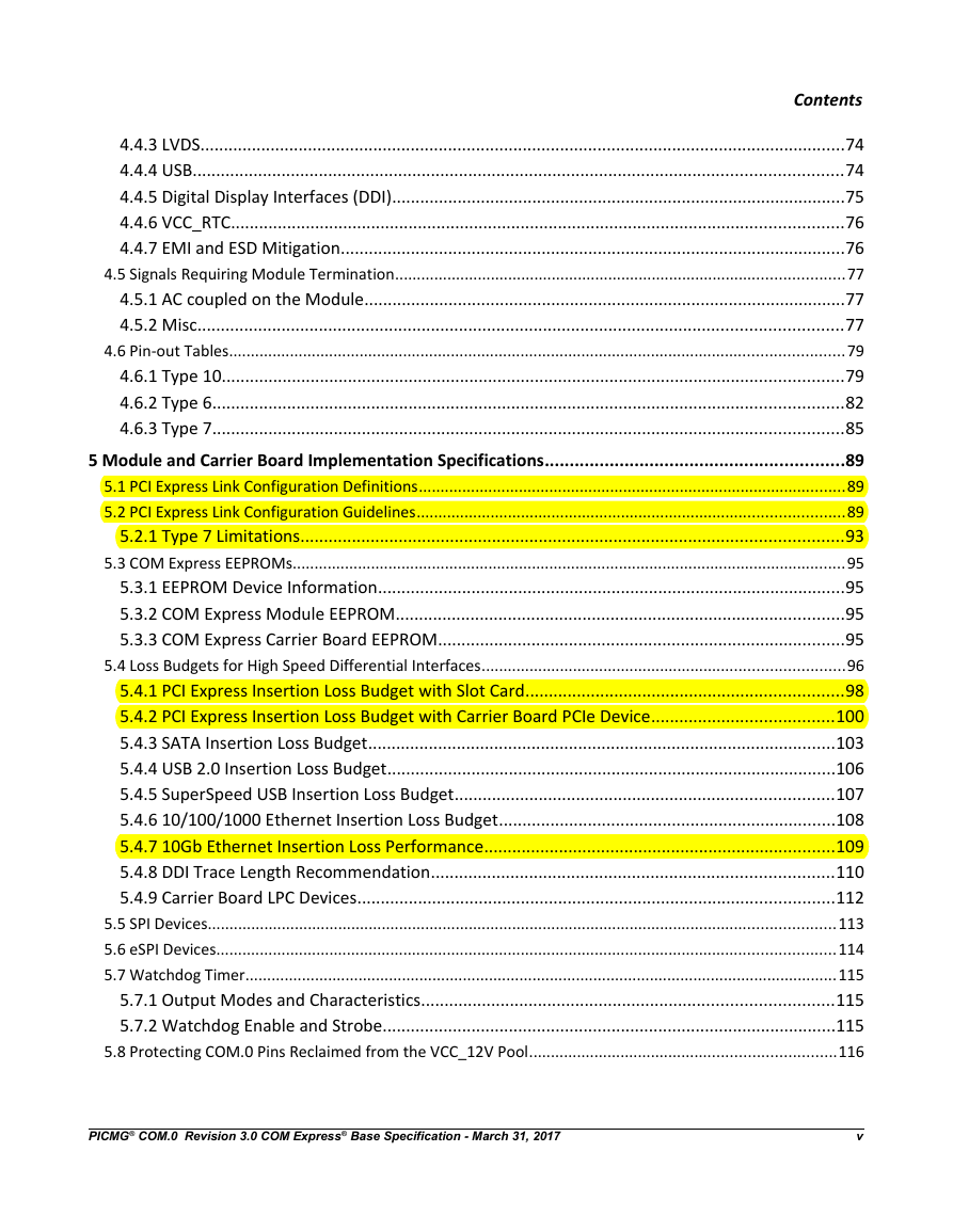
5 Module and Carrier Board Implementation Specifications
5.1 PCI Express Link Configuration Definitions
Lane:
Link:
Link Configuration:
Bucket:
5.2 PCI Express Link Configuration Guidelines
Table 5.1: PCI Express Lane Numbers and Bucket Groupings
Table 5.2: Module Pin-Out Type 6 - Preferred Lane Groupings: Bucket B1
Table 5.3: Module Pin-Out Type 6 - Preferred Lane Groupings: Buckets B3 and B4
5.2.1 Type 7 Limitations
Table 5.4: Module Pin-Out Type 7 - Preferred Lane Groupings, X4 Root Hubs
Type 7 Lane Reversal
Table 5.5: Type 7 X4 Root Hub Without Lane Reversal
Table 5.6: Type 7 X4 Root Hub With Lane Reversal
5.3 COM Express EEPROMs
5.3.1 EEPROM Device Information
5.3.2 COM Express Module EEPROM
5.3.3 COM Express Carrier Board EEPROM
5.4 Loss Budgets for High Speed Differential Interfaces
5.4.1 PCI Express Insertion Loss Budget with Slot Card
Figure 5-1: PCI Express Insertion Loss Budget with Slot Card
Table 5.7: PCI Express Insertion Loss Budget, 1.25 GHz with Carrier Board Slot Card
Table 5.8: PCI Express Insertion Loss Budget, 2.5 GHz with Carrier Board Slot Card
5.4.2 PCI Express Insertion Loss Budget with Carrier Board PCIe Device
Figure 5-2: PCI Express Insertion Loss Budget with Carrier Board PCIe Device
Table 5.9: PCI Express Insertion Loss Budget, 1.25 GHz with Carrier Board PCIe Device
Table 5.10: PCI Express Insertion Loss Budget, 2.5 GHz with Carrier Board PCIe Device
Table 5.11: PCI Express Trace Routing Guidelines
5.4.3 SATA Insertion Loss Budget
Figure 5-3: SATA Insertion Loss Budget
Table 5.12: SATA Gen 1 Insertion Loss Budget, 1.5 GHz
Table 5.13: SATA Gen 2 Insertion Loss Budget, 3.0 GHz
Table 5.14: Serial ATA Trace Routing Guidelines
5.4.4 USB 2.0 Insertion Loss Budget
Figure 5-4: USB 2.0 Insertion Loss Budget
Table 5.15: USB Insertion Loss Budget, 400 MHz
5.4.5 SuperSpeed USB Insertion Loss Budget
Figure 5-5: SuperSpeed USB Insertion Loss Budget
Table 5.16: SuperSpeed USB Insertion Loss Budget
5.4.6 10/100/1000 Ethernet Insertion Loss Budget
Figure 5-6: 10/100/1000 Ethernet Insertion Loss Budget
Table 5.17: 10/100/1000 Ethernet Insertion Loss Budget, 100 MHz
5.4.7 10Gb Ethernet Insertion Loss Performance
Figure 5-7: 10GBASE-KR Trace Length Budget
Table 5.18: 10GBASE-KR Trace Length Budget
5.4.8 DDI Trace Length Recommendation
Figure 5-8: DDI Trace Length
Table 5.19: DDI Trace Length
5.4.9 Carrier Board LPC Devices
Figure 5-9: Typical Routing Topology for a Module LPC Device
5.5 SPI Devices
Figure 5-10: Typical SPI topology
5.6 eSPI Devices
5.7 Watchdog Timer
5.7.1 Output Modes and Characteristics
Table 5.20: Watchdog Timer Output Modes
5.7.2 Watchdog Enable and Strobe
Table 5.21: Watchdog Enable and Strobe Parameter Range
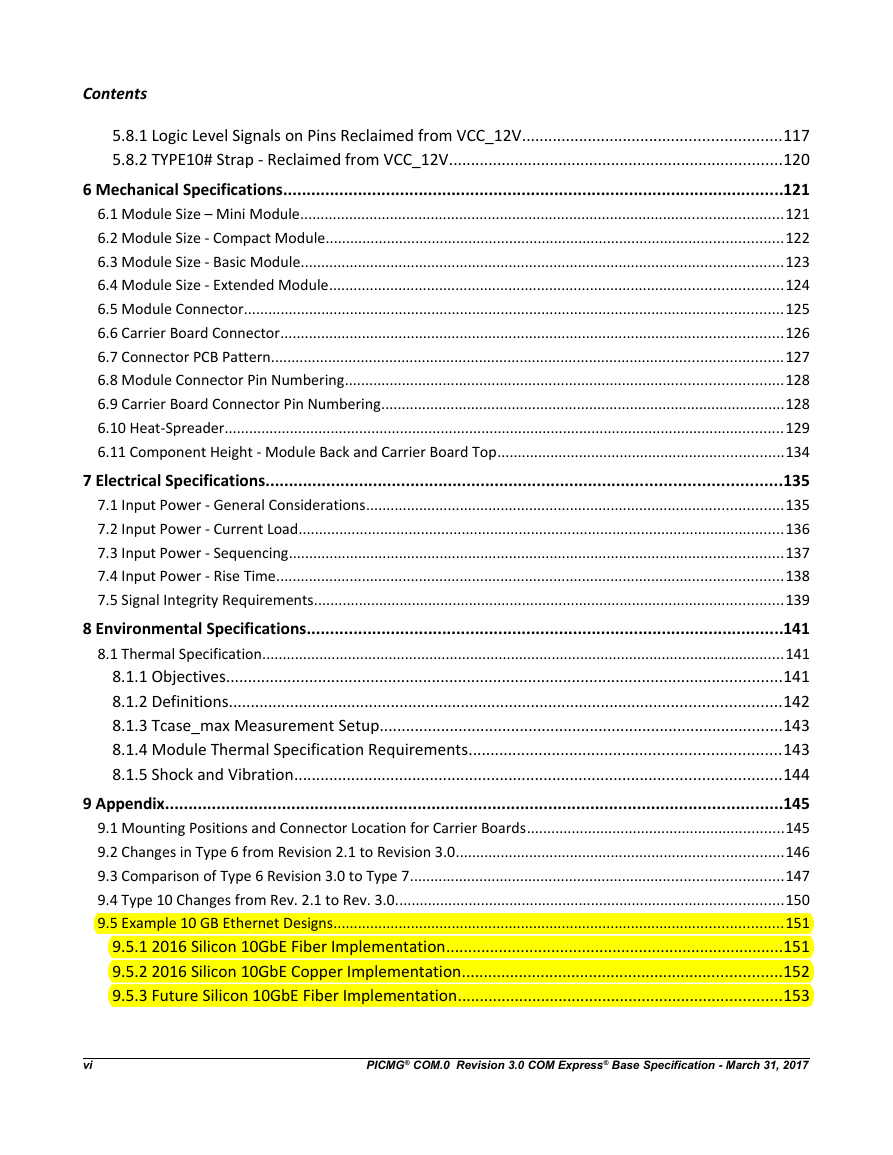
5.8 Protecting COM.0 Pins Reclaimed from the VCC_12V Pool
5.8.1 Logic Level Signals on Pins Reclaimed from VCC_12V
Figure 5-11: Protecting Logic Level Signals on Pins Reclaimed from VCC_12V, Diode Based Method
Figure 5-12: Protecting Logic Level Signals on Pins Reclaimed from VCC_12V, FET Based Method
5.8.2 TYPE10# Strap - Reclaimed from VCC_12V
6 Mechanical Specifications
6.1 Module Size – Mini Module
Figure 6-1: Mini Module Form Factor
6.2 Module Size - Compact Module
Figure 6-2: Compact Module Form Factor
6.3 Module Size - Basic Module
Figure 6-3: Basic Module Form Factor
6.4 Module Size - Extended Module
Figure 6-4: Extended Module Form Factor
6.5 Module Connector
Figure 6-5: Module Receptacle
6.6 Carrier Board Connector
Figure 6-6: Carrier Board Plug
6.7 Connector PCB Pattern
Figure 6-7: Connector PCB Pattern
6.8 Module Connector Pin Numbering
Figure 6-8: Module Connector Pin Numbering
6.9 Carrier Board Connector Pin Numbering
Figure 6-9: Carrier Board Connector Pin Numbering
6.10 Heat-Spreader
Figure 6-10: Overall Height for Heat-Spreader in Mini, Compact, Basic and Extended Modules
Figure 6-11: Mini Module Heat-Spreader
Figure 6-12: Compact Module Heat-Spreader
Figure 6-13: Basic Module Heat-Spreader
Figure 6-14: Heat-Spreader Specification for Extended Module
6.11 Component Height - Module Back and Carrier Board Top
Figure 6-15: Component Clearances Underneath Module
7 Electrical Specifications
7.1 Input Power - General Considerations
7.2 Input Power - Current Load
Table 7.1: Input Power - Pin-Out Type 10 Modules (Single Connector, 220 pins)
Table 7.2: Input Power - Pin-Out Type 6/7 Modules (Dual Connector, 440 pins)
7.3 Input Power - Sequencing
Figure 7-1: Power Sequencing
Table 7.3: Power Sequencing
7.4 Input Power - Rise Time
Figure 7-2: Input Power Rise Time
7.5 Signal Integrity Requirements
Table 7.4: Signal Integrity Requirements
8 Environmental Specifications
8.1 Thermal Specification
8.1.1 Objectives
8.1.2 Definitions
8.1.3 Tcase_max Measurement Setup
Figure 8-1: Tcase_Max Measurement Point
8.1.4 Module Thermal Specification Requirements
8.1.5 Shock and Vibration
9 Appendix
9.1 Mounting Positions and Connector Location for Carrier Boards
Figure 9-1: Carrier Board Mounting Positions
9.2 Changes in Type 6 from Revision 2.1 to Revision 3.0
Table 9.1: Comparison Type 6 Rev. 2.1 with Type 6 Rev 3.0
9.3 Comparison of Type 6 Revision 3.0 to Type 7
Table 9.2: Comparison Type 6 Rev. 2.1 with Type 7 Rev 3.0
9.4 Type 10 Changes from Rev. 2.1 to Rev. 3.0.
Table 9.3: Type 10 Rev. 2.1 to Rev. 3.0 Comparison
9.5 Example 10 GB Ethernet Designs
9.5.1 2016 Silicon 10GbE Fiber Implementation
Figure 9-2: 10G Ethernet Design for Fiber PHY with Broadwell DE
9.5.2 2016 Silicon 10GbE Copper Implementation
Figure 9-3: 10G Ethernet Design for Copper PHY with Broadwell DE
9.5.3 Future Silicon 10GbE Fiber Implementation
Figure 9-4: 10G Ethernet Design for Fiber PHY with Future SoC
9.5.4 Future Silicon 10GbE Copper Implementation
Figure 9-5: 10G Ethernet Design for Copper PHY with Future SoC



 2023年江西萍乡中考道德与法治真题及答案.doc
 2012年重庆南川中考生物真题及答案.doc
 2013年江西师范大学地理学综合及文艺理论基础考研真题.doc
 2020年四川甘孜小升初语文真题及答案I卷.doc
 2020年注册岩土工程师专业基础考试真题及答案.doc
 2023-2024学年福建省厦门市九年级上学期数学月考试题及答案.doc
 2021-2022学年辽宁省沈阳市大东区九年级上学期语文期末试题及答案.doc
 2022-2023学年北京东城区初三第一学期物理期末试卷及答案.doc
 2018上半年江西教师资格初中地理学科知识与教学能力真题及答案.doc
 2012年河北国家公务员申论考试真题及答案-省级.doc
 2020-2021学年江苏省扬州市江都区邵樊片九年级上学期数学第一次质量检测试题及答案.doc
 2022下半年黑龙江教师资格证中学综合素质真题及答案.doc